

Page 1

VP100/20NET DISPLAY
Technical Instructions
Sipronika d. o. o., Tržaška 2, 1000 Ljubljana, Slovenija, Tel.: 01/ 421-52-50, Fax: 01/ 421-52-55,
E-mail: info@sipronika.si, Internet: http://www.sipronika.si
Ljubljana, 12. 5. 2014, Copyright Sipronika 2008, All rights reserved vp100net-engv439
Page 2

Sipronika d.o.o.
Tržaška 2,
1000 Ljubljana
Tel.: 01/4215-250
Fax: 01/4215-255
Internet: http://www.sipronika.si
E-mail: info@sipronika.si
May 12, 2014
Page 2 of 25 VP100/20NET
Page 3

CONTENTS
1. INTRODUCTION __________________________________________________ 4
2. MOUNTING AND CONNECTION OF VP100/20NET ____________________ 5
2.1 Mounting ____________________________________________________________ 5
2.2 Connection and operation of the display __________________________________ 5
2.3 OUT connector, the connection diagrams _________________________________ 6
2.4 Contacts of the relay ___________________________________________________ 8
3. SETTINGS, THE USE OF THE KEYS "MENU" AND "SET"_____________ 9
3.1 Description of menus __________________________________________________ 9
4. PROGRAMMING OF MESSAGES __________________________________ 12
4.1 General ____________________________________________________________ 12
4.2 Installation __________________________________________________________ 12
4.3 A short description of the message-programming procedure ________________ 12
4.4 The programming interface ____________________________________________ 13
4.5 Description of menus _________________________________________________ 16
4.5.1 Options menu ___________________________________________________________ 16
5. THE DISPLAY’S REAR, D-SUB CONNECTORS ______________________ 22
6. TECHNICAL DATA_______________________________________________ 24
7. ARRANGEMENT OF JUMPERS ____________________________________ 25
VP100/20NET Page 3 of 25
Page 4
1. INTRODUCTION
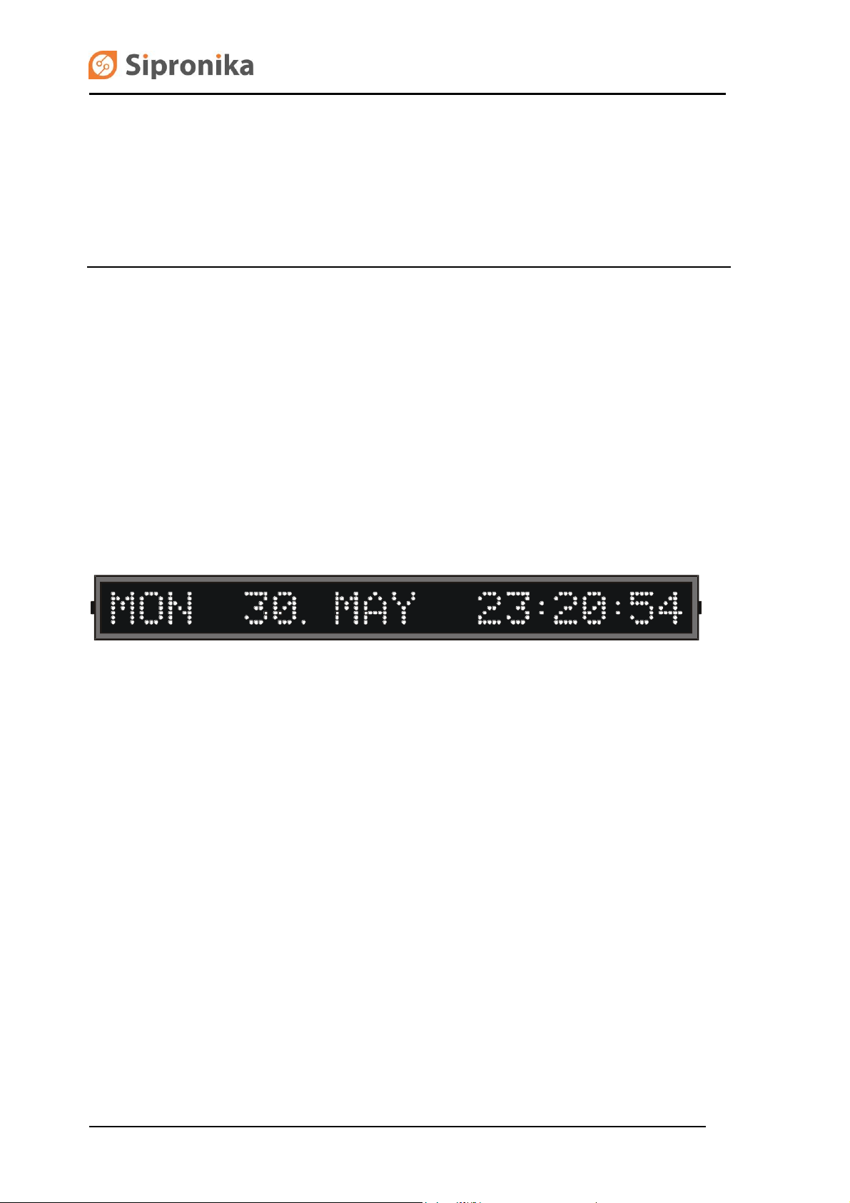
The VP100/20 NET display is designed for displaying time and messages.
The time is displayed in the following format: day of the week, day of the month, month, hours,
minutes, and seconds. The messages can be displayed in the static, blinking or scrolling form. On
the display, up to 20 characters can be displayed simultaneously.
The display can be connected to a network through its Ethernet RJ-45 connector, through which the
programming of messages and the time synchronization with the NTP server are executed. The
messages are programmed on a personal computer which is connected to the network and on which
the Message Editor program is installed (the program is enclosed in the package).
Fig. 1: Front view.
Page 4 of 25 VP100/20NET
Page 5
2. MOUNTING AND CONNECTION OF VP100/20NET
2.1 Mounting
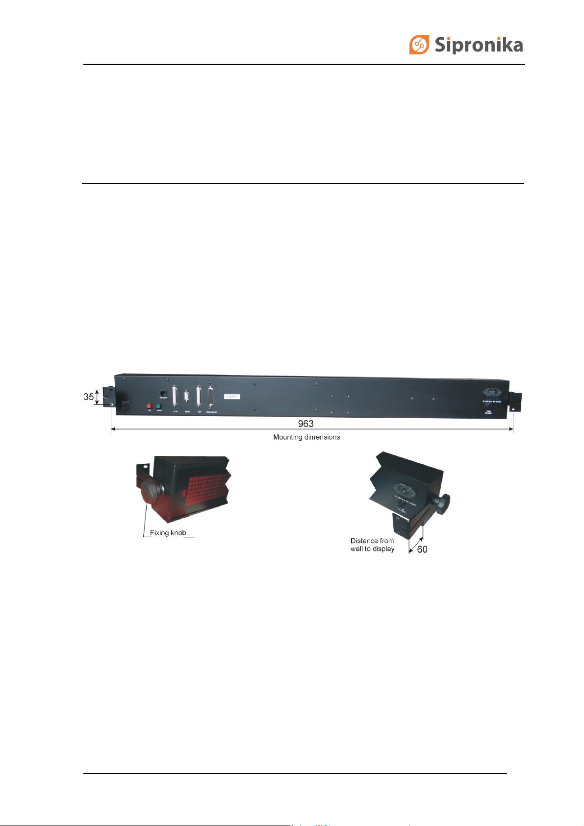
The regular, single-type display VP100/20 NET is adapted for the wall mounting. For this purpose,
two right-angled carriers, with screws and wall plugs are enclosed in the package. The double-type
display is designed for the ceiling mounting.
Fig. 2: Wall mounting, all dimensions in mm.
2.2 Connection and operation of the display
Connect VP100/20 NET to the mains. As it has no "power-on" switch, it will start functioning
immediately. You must also connect the device to the Ethernet network. The connector for the
Ethernet connection is installed at the rear of the enclosure. It is labeled “Network”. The time is
displayed following the introductory text. If after the device's last turning-off the internal memorysupporting battery has been discharged, all messages stored in the display will be deleted.
Immediately after the device has been switched on, a dot is displayed between the date and the
hour, which means that the display has not yet been synchronized with the NTP server's time. Using
VP100/20NET Page 5 of 25
Page 6
the two keys at the display's rear or the Message Editor program, it is necessary to set the display's
IP address, the sub-network's mask, the default gateway and the NTP server's IP address on the
occasion of the first turning on. These settings are of vital importance for successful programming of
messages and for time synchronization via the network.
When the communication between the display and the NTP server has been established, the
display's internal clock will become synchronized, and the dot appearing between the date and the
time of the day will disappear.
If there is a DHCP server provided in the network, all of the settings can be managed by the server –
the DHCP client should be switched on in the menu (this is also the default setting). All the network
settings can be remotely controlled by Message Editor program (MED), which alone seeks for the all
displays connected to the local network. The message programming and time synchronization of the
display are not possible without prior proper network settings.
2.3 OUT connector, the connection diagrams
To the connector labeled OUT you can connect another VP100/20-type display (a version without a
network interface), provided it is set to a baud rate of 9600 and to the 8N1 data format. The
connection can be realized in two different ways:
using RS232: for short distances (of up to 15 m);
using 20-mA current loop: for longer distances between the two displays.
You can choose between these two connection alternatives by means of jumpers inside the display.
WARNING
Please make sure to unplug the device
before opening the enclosure!
In order to be able to manipulate the jumpers, it is necessary to open the enclosure: please unscrew
the four screws that hold the cover on its right side, pull out the cover, and pull out the plexiglas piece
and the small blocking plate. Unscrew the screws holding the displaying plates in their middle. Pull
out carefully the right displaying plate. Before pulling it out completely, you must unplug the flat cable
from its socket and interrupt pull apart the contacts of the power supply cable. As a result, the
jumpers on the microcontroller board become accessible. After setting them appropriately, close the
enclosure, proceeding in the reverse order.
Page 6 of 25 VP100/20NET
Page 7
JP7
JP16
JP19
VP100/20 NET
x
RS232
telegrams
VP100/20
RS232
x
telegrams
JP7
JP8
JP9
JP10
JP11
JP14
JP15
JP16
JP17
JP18
JP19
VP100/20 NET
x x x x x
passive
passive
20 mA
active
active
telegrams
VP100/20
20 mA
passive
passive
active
active x x x x x telegrams
3
2 7 7
2
3
VP100/20 NET
C
onnector
OUT
VP100/20
Connector
IN
100
24
17 100 25
23
+V1
100
24 17
+V2
100 25
23
VP100/20 NET
C
onnector
OUT
VP100/20
Connector
IN
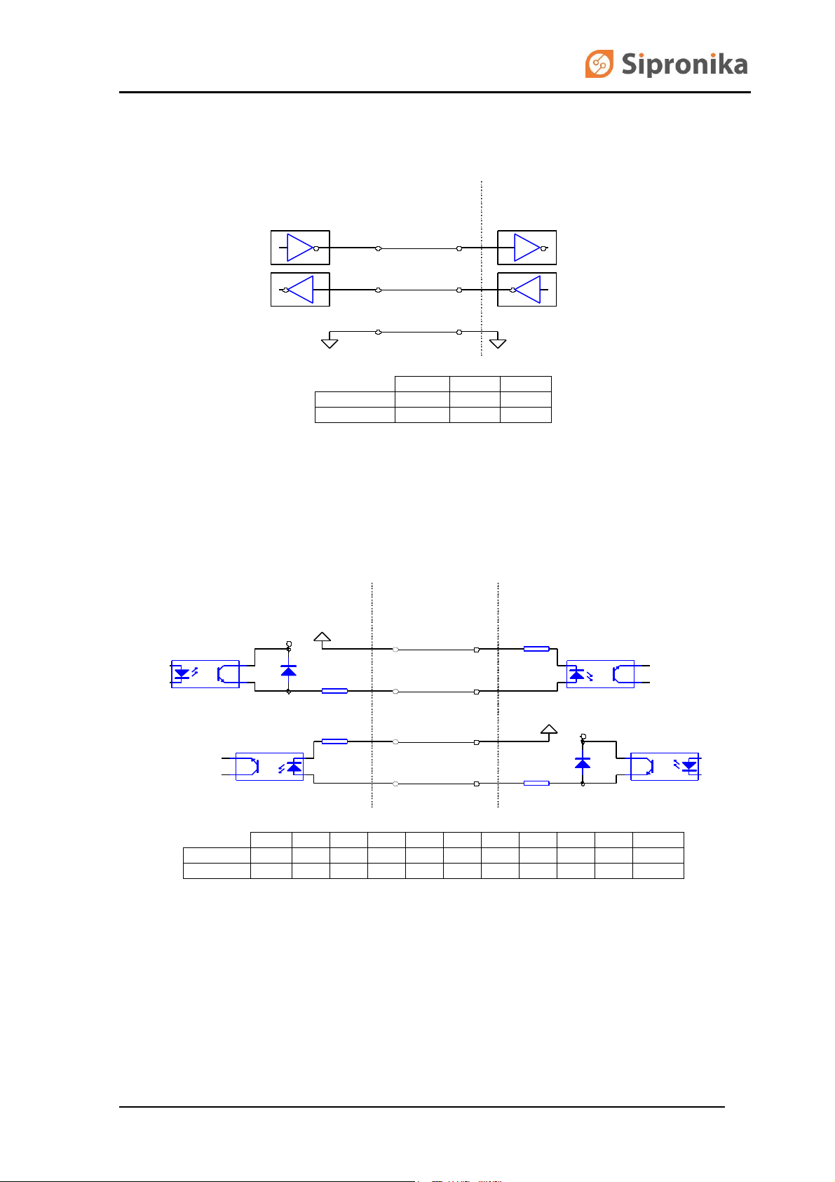
Fig. 3: The use of RS232 for the connection between the VP100/20 NET and the ordinary
VP100/20. The table shows the setting of jumpers in both displays.
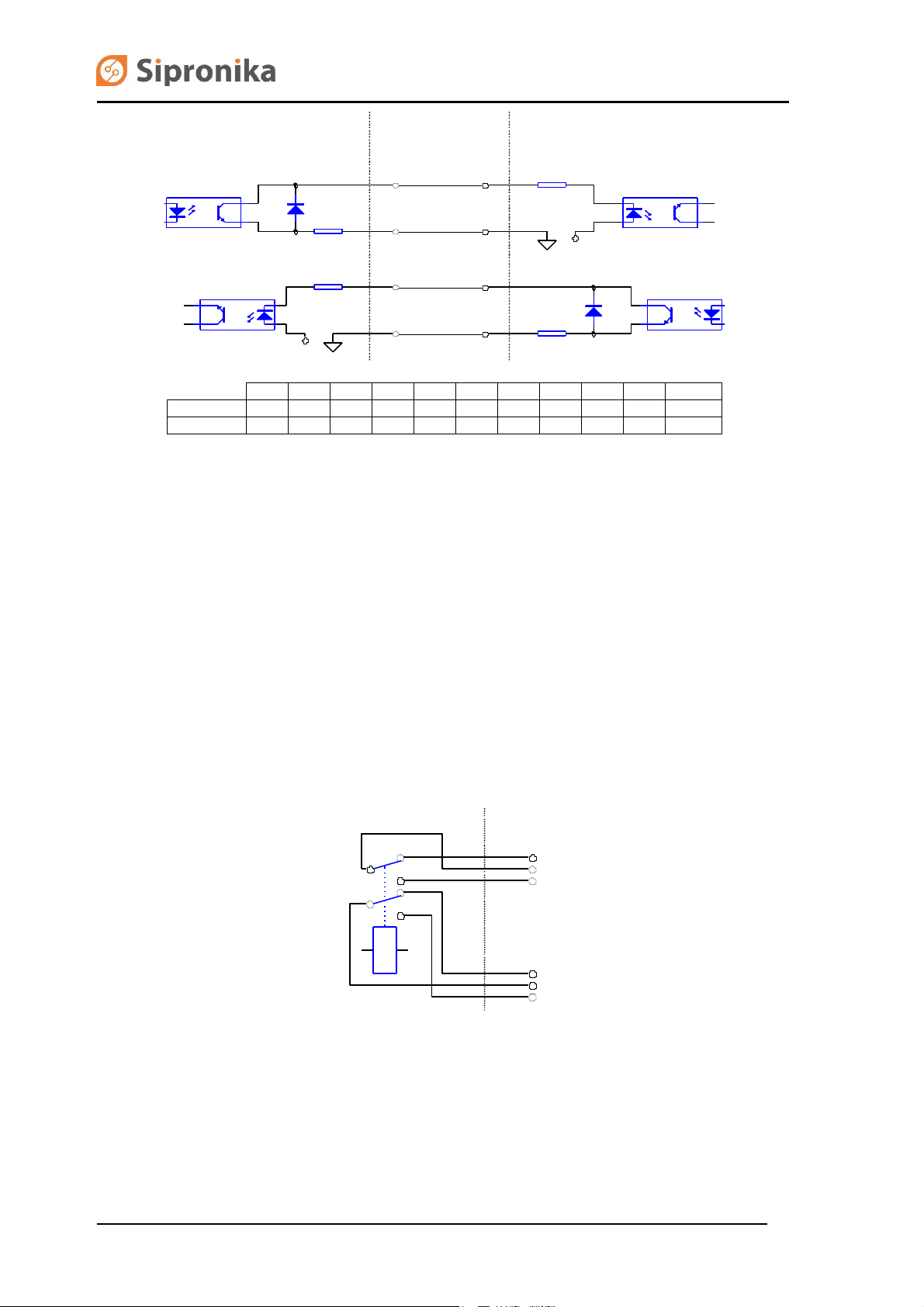
Fig. 4: The use of 20 mA current loop; here the outputs are active, and the inputs passive.
VP100/20NET Page 7 of 25
Page 8
JP7
JP8
JP9
JP10
JP11
JP14
JP15
JP16
JP17
JP18
JP19
VP100/20 NET
x x x x x
active
active
20 mA
passive
passive
telegrams
VP100/20
20 mA
active
active
passive
passive
x x x x x
telegrams
1
4
VP100/20NET
Conn. RELAY
2
3
5
6
100
24
17
100
25
23
100
24
17
100 25
23
+V2
+V1
VP100/20 NET
C
onnector
OUT
VP100/20 NET
C
onnector
IN
Fig. 5: The use of 20 mA current loop; here the outputs are passive, and the inputs active.
2.4 Contacts of the relay
To the relay's connection terminals you can connect an external sound source, which will provide
sound accompaniment for the messages for which the "loud sound" option is checked. The figure
below shows the arrangement of the connection terminals.
Fig. 6: The relay's connection terminals.
Page 8 of 25 VP100/20NET
Page 9

3. SETTINGS, THE USE OF THE KEYS "MENU" AND
"SET"
The keys labeled MENU and SET at the display's rear can be used to set the time, language,
brightness, time zone, times of transitions from the standard time to the Daylight Saving Time and
vice versa, the display's IP address, the subnetwork's mask, the default gateway and the NTP
server's IP address. The display saves all the settings in its memory and uses them the next time it is
turned on.
The setting is performed according to the following procedure:
choose the desired setting by pressing the MENU key;
if you press the SET key, the current value of the setting chosen is displayed; the
character/digit than you can change at that time is blinking;
by pressing the SET key for a longer time, you can change the setting at the blinking place,
by pressing the SET key for a short time, you are moved to the next place/digit,
once you are satisfied with the setting, press the MENU key to save the setting,
if you do not press any key for more than 30 seconds, the display will return to the normal
displaying of time and messages; the setting chosen last (with the exception of the
brightness) will not be saved.
WARNING: While you perform the setting procedure, the communication with the Personal
Computer is interrupted – the sending of messages and settings is not possible.
3.1 Description of menus
TIME & DATE
Here you can set the display's date and time with an accuracy of one second. The time you have set
will be adopted when you press the MENU key. If the display is connected with the NTP server, the
time received from the server will prevail.
LANGUAGE
In this menu you can choose the language that will be used for displaying the date and the time; the
abbreviations of the names of months and days of the week will be displayed in the language you
have chosen here.
BRIGHTNESS
Here you can select the display's brightness. The degrees you can choose range from 1 (the lowest
brightness) to 3 (the highest brightness).
VP100/20NET Page 9 of 25
Page 10

SERIAL NUMBER
If you press the SET key, the display's serial number is displayed; it is significant for the
programming of messages: your must enter it while working with the message-programming program
(see the chapter on the programming of messages). The number is written also at the display's rear;
it can not be altered.
TIME ZONE
Within this menu, you can set the difference between the local time and the UTC. You can set the
algebraic sign, the hours and the minutes. The display calculates the local time according to the
formula: local time = UTC + the difference. For Central Europe, the difference amounts to +01:00 for
the standard time, and +02:00 for the Daylight Saving Time. If you wish to display the UTC time, set
both values to +00:00.
WINTER/SUMMER, SUMMER/WINTER
Here you can set the date and the hour of the automatic transition from the standard time to the
Daylight Saving Time (Summer Time) and vice versa.
You can set the exact transition moment for the current year, or universally – for several years. In the
case of the universal setting, you set a day of the week and a date containing two asterisks ('**') in
place of the year. The transition will happen when the chosen day of the week comes for the first
time, provided the then date is later than the one set or equal to it.
Example:
In Central Europe, the transition is put into effect on the last Sunday in March, at 02:00:00 AM (local
time). The universal (default) setting is: SUN 25.03.** 02:00:00.
The transition from the Daylight Saving Time to the standard time is put into effect on the last Sunday
in October. The universal (default) setting is: SUN 25.10.** 03:00:00.
On the other hand, the settings valid only for the year 2005 are the following:
*** 27.03.05 02:00:00 and *** 30.10.05 03:00:00.
With these settings, next year it will be necessary to set the transition times anew.
IP ADDRESS, SUBNET MASK, DEFAULT GATEWAY
The display's IP address, subnet mask, and default gateway are set in accordance with the data of
the existing network to which you intend to connect the display.
A DHCP client is integrated in the display, which can set alone in relation with a DHCP server (if
provided in the network) all the proper network settings. The DHCP client is activated if “DHCP: Y” is
chosen. If “DHCP: N” is chosen, the client is switched off and all the network settings should be set
manually.
If DHCP is switched on, then menus »subnet mask« and »default gateway« can only be inspected
but not changed.
NTP SERVER 1, NTP SERVER 2, NTP SERVER 3
Using the SNTP protocol, the display can set its internal clock automatically. For this purpose, it must
have access to the NTP time server. In these menus, IP addresses of up to 3 NTP servers can be
set. The display is synchronized by the first available server. A setting “0.0.0.0” means that the server
is not set.
TIME FORMAT
In newer versions it’s possible to display time in various formats. In this menu you can choose
between two formats:
Page 10 of 25 VP100/20NET
Page 11

- Day of week, day of month, month, hours : minutes : seconds
Example: MON 12. MAY 10:15:30
- Day of year, day of month, month, hours : minutes : seconds
Example: 132 12. MAY 10:15:30
EXIT
If you press the SET key, the display returns to the normal displaying of time and messages.
However, if you press the MENU key, the display begins a new circle of settings.
VP100/20NET Page 11 of 25
Page 12

4. PROGRAMMING OF MESSAGES
4.1 General
Besides the time, the display can display also messages. For the programming and sending of
messages, a personal computer and the Message Editor program are used. It is verified that the
program operates under Microsoft Windows 98, 2000 and XP.
4.2 Installation
Insert the CD in the drive and run "med437a_setup.exe" setup program.
In the installation program, choose the language and the folder in which you want to install the
program, as well as the program group into which the icons will be installed. When the program is run
for the first time, all the default settings are set. The program menus are displayed in the language
chosen during the installation.
Program communicates with the display using TCP protocol on port 8000 and UDP on ports 54324
and 54325. An eventual firewall must allow this type of communication otherwise the program can
not work properly.
4.3 A short description of the message-programming procedure
After the program has been installed, you must "add" at least one display by specifying its name,
serial number, and IP address. With the versions having no network connection, instead of the IP
address you must specify the computer's serial interface (COM1 or COM2), through which the
communication with the display will take place.
After the basic settings have been executed, individual messages should be programmed according
to the following procedure:
select the target display,
select the message's consecutive number, ranging from 1 to 31,
Page 12 of 25 VP100/20NET
Page 13

specify the displaying mode: a running or a static/flashing message,
enter the message's text,
specify the time of displaying: "immediately" or at a specified time,
specify the number of repetitions for the message,
specify the time period between the repeating appearances of the message,
specify the message's priority: in the event that the specified displaying times for individual
messages overlap, the message with the higher priority will be displayed,
select the type of the audio accompaniment: "without", "weak", "loud",
once you are satisfied with the format and the settings, send the message to the display by
clicking the Send button.
The messages can be sent to the display also via e-mail. The message must be of the text format
(and not of the HTML format) while its subject line must contain predetermined character sequences
on the basis of which the software recognizes the message type (See the Options menu -> E-mail
settings). A message received through e-mail is stored as the message No. 0 in the program;
however, it can not be changed manually by means of the program. Every message received through
e-mail must be confirmed by a press of the large button (Confirm Message) which appears instead of
the Send button after reception of the message. In the event that a new message arrives via e-mail
before the previous message has been confirmed, the displaying of the previous message is
interrupted, and the message received last is displayed. After the last message received has been
confirmed the displaying of the previous one continues. The program records also a log of messages
received by e-mail. The log is located in the directory in which the program has been installed, in the
text-format file EmailLog.txt. Into it, all the messages received by e-mail, their confirmations, and any
problems occurring in the communication with the POP (e-mail) server are recorded.
Each display has its own serial number and its own name – you can give it any name you like within
the MED program.
The display sends confirmations of having received messages. In the MED program, you can switch
on/off the operation mode of waiting for the confirmation.
Attention: during the setting mode of operation, the display does not send confirmations of the
reception of messages! So if the waiting for the confirmation is activated, do not program the display
while executing its settings.
4.4 The programming interface
The programming interface is divided into four divisions. In the above division, you can choose
between individual displays (at the Display caption) and the messages to be displayed on them (at
the Message caption); underneath, on the left side, the time settings are performed, and on the right
side the remaining settings of the messages. In the left lower part there is a window in which the
messages are written and edited.
In the continuation, individual elements of the programming interface are described.
Display
Here you can choose the display to which you want to send the messages. You can give the displays
any names you like, using the menus Options–>Settings–>Displays.
Message
Here you can specify the consecutive number of the message that you wish to program, edit or
cancel, ranging from 1 to 31.
VP100/20NET Page 13 of 25
Page 14

1
Time of Next Appearance
For every message, you can specify the precise time of the message's first displaying. The time is
entered using the fields "Day" and "hour:minute:second". The day of the week can be entered either
using the day's consecutive number (1 stands for Monday) or by entering the first three letters1 of the
day's name. If you enter "xxx" as the day, the day of the week will not affect the displaying.
Example:
If you enter "xxx" and "15:23:30", the message will be displayed for the first time at the time entered
right, regardless of the day of the week; on the other hand, if you enter "Mon" "15:23:20", the
message will be displayed on Monday for the first time.
Period
Every message can be either displayed only once or repeated periodically – in the latter case you
must specify the corresponding period of repetition (the time between individual repetitions). The
period can be specified with a step of 1 minute in the range from 1 minute to 1 week. If you want the
message to be displayed only once, set the period to 0.
Immediate Message
Select this option if you want the message to be displayed immediately. When displayed for the first
time, such message will override any other message being displayed, regardless of the priority; the
priority will, however, be taken into consideration at any subsequent displayings.
The abbreviation depends on the language chosen.
Page 14 of 25 VP100/20NET
Page 15

Scrolling Message
The message will be displayed in a scrolling mode. The number of consecutive times a text can be
repeated is equal to the number set under "No. of Repetitions".
Soft End
If this option is activated, at the end of the running message 20 blank characters will be added – this
way all the message's characters will be able to »travel« over the whole displaying field, from the
right to the left. Reading the message will be facilitated. Because of the advantages mentioned, we
recommend that this option is activated at all times.
Sound
As regards the audio accompaniment of the message, you can choose between three alternatives:
no sound,
a weak sound – the audio accompaniment will be performed by the built-in buzzer,
a loud sound – besides the internal buzzer, also the relay is activated; the relay can switch
on an external alarm.
No. of repetitions
The value entered in this field determines how many times in succession (without interruption) the
message should be repeated. You can choose any number between 1 (no repetition) and 9.
Priority
For every message, a priority should be specified. You can choose between three alternatives: low,
normal, and high.
The priority of messages is important in the event that for two or more messages the specified
displaying time is the same, or the displaying time specified for a message starts while another
message is being displayed. The higher-priority message will »override« the lower-priority messages.
If the messages' priorities are equal, the one with the lowest consecutive number will be displayed.
Send
By clicking this button, you can send the message to the display. If the reception confirmation is
activated, the sending will be repeated if it has not been successful. If even after some repetitions the
confirmation has not been received, an error message will appear.
Remove
By this button, a selected message can be cancelled from the display.
Entering and editing of the message's contents
The contents of a message should be entered into the big editing field located in the lower left part. In
the event of a normal, static message, one line of text in the editing field (20 characters) corresponds
to one line on the display. The lines will be displayed one after the other. Altogether, there can be up
to 11 of them. For every line, you can specify the time (from 1 s to 59 s) and the mode of displaying –
static or flashing. This can be done on the right side of the field, in the columns Time and Mode. The
contents of individual lines can be aligned with the left or the right margin, or centered, by clicking the
corresponding symbol on the field's upper part: <–, –><– or –>.
A running message can have up to 241 characters. If the option "soft end" is selected, the length is
limited to 221 characters. The contents of a message with a "soft end" will "travel" over the whole
display and »disappear« into the left side.
VP100/20NET Page 15 of 25
Page 16

4.5 Description of menus
4.5.1 Options menu
Delete All Messages
This command deletes all messages from the chosen display.
Send All Messages
This command sends to the selected display all the messages entered through the PC.
Request Messages
As a result of this command, the chosen display will send to the PC all the active messages stored in
its memory.
Copy
With this command, you can transfer all the messages from one display to another. In the process of
copying, all the messages stored in the target display are completely overridden. For example, if you
wish to transfer the messages from Display A to Display B, first select Display A, then select Display
B, and finally execute the Copy command.
Settings
It is possible to set/change three types of parameters: those of the program, those of the display, and
those of the messages received via e-mail.
Page 16 of 25 VP100/20NET
Page 17

Program Settings
You can choose the language of the programming interface (the file containing definitions of the
expressions/ terms used, in the chosen language) and the serial port to which the display is
connected. In the case of displays with a specified IP address, the serial-port selection has no effect.
Advanced Settings
If you check the option »Request Messages on Startup«, the program will immediately after starting
establish a connection with the display, and transfer the active messages from it. In order to have
access to the other settings, you must first enter the following password: Triglav. Within the dialog
box that appears after a successful entering of the password, you can set:
the operation mode of waiting for a confirmation of the message's reception (Wait for Display
to Respond). The default setting: activated.
The number of repetitions (Number of Retries). The number determines how many times the
sending of a message will be retried in the event that it has failed the first time. The default
value: 3.
the setting of the serial-transmission format (Port Settings). It affects only the displays which
are connected directly to the PC’s serial port. The default setting: 8,N,1.
TCP/IP port. The default value: 8000.
E-Mail Settings
Into the first three fields, the e-mail server address (POP3 Server), the username and the password
must be entered. The time specified in Mail Checking Interval is the interval (in seconds) between the
program's consecutive checks of the new messages at the address mentioned above. If the Mail
Checking Interval is set to 0, the program does not communicate with e-mail server. If the box
VP100/20NET Page 17 of 25
Page 18

»Display Sender's E-Mail Address« is checked, the sender's address will also be shown on the
display, in front of the message itself.
In the menu »Display« there is an option to choose which emails are shown: either all, or those which
in include »+d« in the subject.
In the submenu »Mail display mode« it is set which and how emails are shown. The choice of how
the emails are shown is up to the sender by setting »Read display mode from subject«. The other
possibility is to set this option in the program for all emails by choosing “Always use following display
mode”.
Message Repetition Mode
If the option »Repeat message until confirmed« is chosen, the received email is occurring until the
user confirms the reception by clicking the »Confirm email« button. The number of occurrences can
be limited: either through Message Editor or by the email subject.
Message Display Mode
If the choice is left to the sender, the option »Read display mode from subject« should be set.
The email subject should include proper strings, which correspond to those set in the Message
Editor. The following parameters can be set:
scrolling message (Scrolling), default: +l,
beep when an email occurs (Beep), default: +b
beep and switching of built-in relay (Sound ON), default: +s
number of email occurrences (Repeat), default: +n; in the subject a number should be given
along with the defined string, e.g. +n5 for 5 occurrences.
Page 18 of 25 VP100/20NET
Page 19

Example:
A sender wants a scrolling message with a beep and 3 occurrences. The e-mail’s subject should,
according to the settings shown on the figure above, include: +l, +b, +n3 and (depending on the
settings) additional +d. The subject is for example: »A message to display +d +l +b +n3«.
If the option »Always use following display mode« is chosen, all the received messages are shown in
the way, which is set fixed. In this case all proper fields are marked and in the field »Repeat« the
number of occurrences is given.
Displays
In order to establish communication with a display, the display should be added to a list in this
submenu.
In this submenu also some other settings can be adjusted. Each of the displays can also be removed
from the list.
When adding displays in the program there are two possibilities how to do it:
manually or
automatically.
Each display can be manually added by clicking the button »Add Display«. Accordingly, all the
network parameters, serial number and name should be set manually. This option is useful especially
when dealing with older versions of the displays, which do not support an automatic search.
VP100/20NET Page 19 of 25
Page 20

When adding a new display, you must enter for it the following basic data:
the display's name – choose any one you like, however, it is obligatory that you enter it (a
name is important especially when several displays are connected: it is exactly through their
respective names that you have access to individual displays in the network;
serial number – it is fixed and unchangeable for each display. You can find it in the display's
menu or read it at the enclosure's rear;
IP Address – the address determined by the existing network; which you have entered in the
display. Example: 192.168.0.25. With the displays that do not have a network connection
(using only the serial port) you should leave this field empty.
The automatic search is started by clicking the button »Network display search«. The program
returns a number for the displays found. All new found displays are added to the display list.
If a name of a certain display on the list is being selected, on the right side its name, serial number
and IP address are being shown.
In the submenu »Network Settings« the display network settings are listed and edited. All current
settings are confirmed by clicking »Refresh settings«. The new settings are inserted into provided
fields.
The fields NTP1, NTP2 and NTP3 are provided for IP addresses of the timeservers. It is necessary to
insert at least one IP address. The addresses of the timeservers which are not currently used should
be set to 0.0.0.0.
Page 20 of 25 VP100/20NET
Page 21

A stratum between 1 and 15 can be assigned to each display. The stratum of a NTP server should
be lower than the display’s stratum, otherwise the synchronization can not be established. By clicking
»Send settings« the settings are sent to the display.
In the submenu »Display info« the display's type, software version and MAC address of the network
interface are listed.
By clicking on »Display settings« the following display settings are being provided: Brightness,
Language, Daylight Saving and Time Zone.
By clicking on »Send settings«the settings are sent to the display. By clicking »Refresh settings« the
current settings are being listed.
Exit
This command is used to close the program. All the settings and messages remain on the hard disk,
and are used on the occasion of the next starting of the program.
VP100/20NET Page 21 of 25
Page 22

5. THE DISPLAY’S REAR, D-SUB CONNECTORS
Fig. 7: A view of the display's rear
On the display's rear side there are various connectors and two keys:
NETWORK Network connector RJ-45, Ethernet 10Base-T/100Base-TX
OUT Output for the time and message telegrams: RS-232 and 20 mA - current loop;
connector: DB25,
MENU, SET Keys for performing various settings of the display: time, brightness, language,
time zone, network settings …
RELAY Output with the terminals of a relay which can close the circuit when the
messages are displayed; connector: DB 9
FUSE Fuse – 5 A, slow blow;
230 V Euro-socket for the mains connection;
PC IN , IN Auxiliary inputs – for service purposes only;
Page 22 of 25 VP100/20NET
Page 23

Connector OUT
1
14
2
15
3
16
4
17
5
18
6
19
7
20
8
21
9
22
10
23
11
24
12
25
13
OUTPUT TLX/20 mA -
OUTPUT TLX/20 mA +
OUTPUT TLX/RS232
GROUND
INPUT RX_INF/RS232
INPUT RX_INF/20 mA +
INPUT RX_INF/20 mA -
Connector RELAY
1
6
2
7
3
8
4
9
5
ON1
COM1
OFF1
ON2
COM2
OFF2
Connector PC IN
TXD (PC)
GROUND
RXD (PC)
1
14
2
15
3
16
4
17
5
18
6
19
7
20
8
21
9
22
10
23
11
24
12
25
13
DTR (PC)
RTS (PC)
Fig. 8: The pins on the display's connectors.
VP100/20NET Page 23 of 25
Page 24

Displaying
characteristics:
up to 20 characters at a time, height of characters: 50 mm, format
of characters: 5x7, pixel diameter: 5 mm, color: red or green
Network interface:
10Base-T/100Base-TX Ethernet 10/100Mbit; connector: RJ 45
Outputs:
Selectable by jumpers: RS-232/20 mA (passive/active);
DB25 female connector
Output-telegram
format:
32 ASCII characters, once per minute
<Stx>D:23.05.09;T:6;U:11.45.24;#*S!<Etx>
Baud rate:
9600 bps (output signals)
Framing:
8N1 – 8 data bits, no parity, 1 stop bit
Relay output:
2 normally closed contacts and 2 normally open contacts,
Relay: Matsushita DS2Y
Max. allowed load: 0.3 A (at 125 V AC), 0.3 A (at 110 V DC),
1 A (at 30 V DC),
DB9 female connector
Number of messages:
31+1
Length of messages:
up to 241 characters in the case of the running messages,
up to 220 characters in the case of the static, one-line messages
Internal clock:
Accuracy: 210
–5
(in the case of autonomous operation);
battery-powered (after the display has been turned off)
Battery backup:
In case of a power failure, the internal clock runs up to 10 years
following the date of production;
the messages remain in the memory for at least 100 hours after the
display has been turned off
Power supply:
85 – 264 V AC / 43 – 60 Hz or 120 – 375 V DC
Consumption:
up to 40 W
Fuse:
T 5 A L/250 V–
Dimensions:
996 mm 100 mm 60 mm (not including the mounting carriers)
Weight:
5,3 kg
Protection class:
IP30
Temperature range:
0..50° C
6. TECHNICAL DATA
Page 24 of 25 VP100/20NET
Page 25

JP7JP16
JP8
JP14
JP9
JP15
JP18
JP11
JP17
JP10
U1
JP14, JP15
RX_INFO input – confirmation of the message's reception
(20 mA current loop): active / passive
JP16
selection of the RX_INFO input: RS232 / 20 mA current
loop
JP17, JP18
time-telegram output (20mA current loop): passive /
active
JP7, JP8, JP9, JP10, JP11
reserved (do not change)
7. ARRANGEMENT OF JUMPERS
Function of jumpers:
The jumpers are shown in the following (default) positions:
JP14 active
JP15 active
JP16 RS232
JP17 passive
JP18 passive
VP100/20NET Page 25 of 25
 Loading...