

Page 1

Technical Information
Operating Instructions
LANTIME / TCR
ETX 1HE
Page 2

Contact Information
Meinberg Funkuhren GmbH & Co. KG
Auf der Landwehr 22
D-31812 Bad Pyrmont
Telephone: +49 (0) 52 81 / 9309-0
Telefax: +49 (0) 52 81 / 9309-30
Internet: http://www.meinberg.de
E-Mail: info@meinberg.de
Bad Pyrmont, 14. November 2006
Page 3

Table of Contents
Quick Start..................................................................................................................... 8
Network Timeserver with TCR synchronized time base...............................................9
The Modular System LANTIME.................................................................................10
Supported Network Services.............................................................................. 11
Additional Features and Options........................................................................ 12
User Interface..................................................................................................... 12
Options............................................................................................................... 12
Why to use a Network Timeserver.....................................................................13
Network Time Protocol (NTP).................................................................................... 13
NTP Target......................................................................................................... 14
NTP-Client Installation...................................................................................... 14
IRIG receiver TCR510.................................................................................................16
Description of IRIG-Codes...................................................................................... 16
IRIG-Standard format.............................................................................................. 17
AFNOR-Standard format.........................................................................................18
Overview..................................................................................................................18
Function principle.................................................................................................... 19
Input Signals............................................................................................................ 20
Input for unmodulated codes................................................................................... 20
Input for modulated codes....................................................................................... 21
Input impedance.......................................................................................................21
Booting the Single Board Computer............................................................................22
Configuration User Interface....................................................................................... 23
The Front Panel Layout........................................................................................... 24
TCR Status LEDs............................................................................................... 24
LC Display......................................................................................................... 24
MENU Key.........................................................................................................24
CLR/ACK Key................................................................................................... 24
NEXT Key..........................................................................................................24
INC Key..............................................................................................................24
Page 4

Configuration via LC Display..................................................................................25
The menus in Detail................................................................................................. 26
Root Menu..........................................................................................................26
Menu IRIG state................................................................................................. 26
IRIG system state: Bit 7 ... 0.............................................................................. 27
IRIG system configuration Bit 2 ... 0................................................................. 27
Menu Reference Clock State....................................................................................28
Menu SETUP..................................................................................................... 28
SETUP LAN PARAMETERS........................................................................... 29
SETUP TCR PARAMETERS............................................................................29
The LANTIME configuration interfaces..................................................................... 31
The web interface.........................................................................................................32
Configuration:Main Menu....................................................................................... 33
Configuration: Ethernet........................................................................................... 34
Network interface specific configuration.................................................................36
IPv4 addresses and DHCP..................................................................................36
IPv6 addresses and autoconf.............................................................................. 36
High Availability Bonding................................................................................. 37
Additional Network Configuration.....................................................................38
Configuration: Notification......................................................................................39
Alarm events.......................................................................................................40
E-mail messages................................................................................................. 40
Windows Popup Messages.................................................................................41
SNMP-TRAP messages..................................................................................... 41
VP100/NET wall mount display........................................................................ 41
User defined Alarm scripts.................................................................................42
Alarm messages..................................................................................................42
Configuration: Security............................................................................................43
Password.............................................................................................................44
HTTP Access Control.........................................................................................44
SSH Secure Shell Login..................................................................................... 45
Generate SSL Certificate for HTTPS ................................................................ 46
NTP keys and certificates...................................................................................47
SNMP Parameter................................................................................................47
Configuration: NTP................................................................................................. 48
NTP Authentication............................................................................................51
NTP AUTOKEY................................................................................................ 53
Configuration: Local................................................................................................56
Administrative functions.................................................................................... 57
User Management...............................................................................................58
Administrative Information................................................................................ 59
Software Update................................................................................................. 60
Page 5

Automatic configuration check.......................................................................... 61
Get Diagnostics Information.............................................................................. 62
Web interface language...................................................................................... 62
Configuration: Statistics.......................................................................................... 63
Statistical Information........................................................................................ 64
Configuration: Manual.............................................................................................65
The Command Line Interface...................................................................................... 67
CLI Ethernet.............................................................................................................68
CLI Notification.......................................................................................................71
Alarm events.......................................................................................................71
E-mail messages................................................................................................. 72
Windows Popup Messages.................................................................................73
SNMP-TRAP messages..................................................................................... 73
VP100/NET wall mount display........................................................................ 73
CLI Security.............................................................................................................74
Password.............................................................................................................74
SSH Secure Shell Login..................................................................................... 74
Generate SSL Certificate for HTTPS ................................................................ 75
NTP keys and certificates...................................................................................75
CLI NTP Parameter................................................................................................. 76
CLI NTP Authentication.................................................................................... 77
CLI NTP Autokey.............................................................................................. 77
CLI Local................................................................................................................. 78
Administrative functions.................................................................................... 78
User Management...............................................................................................79
Administrative information................................................................................ 79
Software Update................................................................................................. 80
SNMP Support.............................................................................................................81
Configuration over SNMP ...................................................................................... 83
Examples for the usage of the SNMP configuration features............................ 84
Further configuration possibilities......................................................................85
Send special timeserver commands with SNMP................................................85
Configuration of the timeserver with SNMP: Reference................................... 87
SNMP Traps.............................................................................................................90
SNMP Trap Reference....................................................................................... 91
Attachment: Technical Information.............................................................................92
Skilled/Service-Personnel only: Replacing the Lithium Battery............................. 92
Technical Specifications LANTIME Multipac........................................................92
Page 6

Safety instructions for building-in equipment......................................................... 93
CE-Label.................................................................................................................. 93
Rear Panel Connectors.............................................................................................94
Rear View LANTIME............................................................................................. 95
Technical Specifications TCR510........................................................................... 96
Signal description TCR510................................................................................ 98
Rear Connector Pin Assignments TCR510........................................................ 99
Technical Specifications LAN CPU...................................................................... 100
Rear Connector Pin Assignments LAN CPU...................................................101
VGA, Keyboard Connector Pin Assignments.................................................. 101
Technical Specifications Power Supply.................................................................102
Time Strings...........................................................................................................103
Format of the Meinberg Standard Time String................................................ 103
Format of the GPS167 Capture String............................................................. 104
Format of the SAT-Time String....................................................................... 105
Format of the Uni Erlangen String (NTP) .......................................................106
Format of the NMEA 0183 String (RMC)....................................................... 108
Format of the ABB SPA Time String.............................................................. 109
Format of the COMPUTIME Time String....................................................... 110
Menu Quick Reference.......................................................................................... 111
Declaration of Conformity.....................................................................................112
Manual VP100/NET Display configuration.......................................................... 113
Global Configuration File...................................................................................... 115
Global Option File................................................................................................. 116
Third party software...............................................................................................117
Operating System GNU/Linux.........................................................................117
Samba............................................................................................................... 117
Network Time Protocol Version 4 (NTP)........................................................ 118
mini_httpd........................................................................................................ 118
GNU General Public License (GPL)................................................................119
Timecode (option)..................................................................................................123
Abstract.............................................................................................................123
Principle of Operation...................................................................................... 123
Block Diagram Timecode.................................................................................123
IRIG Standard Format...................................................................................... 124
AFNOR Standard Format.................................................................................125
Assignment of CF Segment in IEEE1344 Code.............................................. 126
Generated Time Codes..................................................................................... 127
Selection of Generated Time Code...................................................................127
Outputs............................................................................................................. 128
Page 7

AM - Sine Wave Output...................................................................................128
PWM DC Output..............................................................................................128
Technical Data..................................................................................................128
USB Stick.............................................................................................................. 129
Menu Structure................................................................................................. 129
Menu Configuration Files................................................................................ 130
Menu Script Files............................................................................................. 131
Keypad locking.................................................................................................131
Reference............................................................................................................... 132
Page 8

Quick Start
TCR: no data available Wed, 18.11.2003
NTP: Not Sync UTC 10:03:30
TCR: NORMAL OPERATION Wed, 18.11.2003
NTP: Not Sync UTC 10:04:10
SETUP: T CR PARAMETERS
IRIG CODE: B122/B123
Are you sure ? Press ...
INC -> YES MENU -> NO
- Approximately one minute after power up no display will be shown. After that the
current state of the TCR receiver and the NTP will be displayed.
==>
- If the TCR receiver remains asynchronous (FAIL LED is still on after 1 minute)
the selected IRIG code and the cable (Input Impedance) are to check. Press
MENU 3 times to enter SETUP menu and then NEXT to enter TCR PARAMETERS. Then press CLR/ACK and then NEXT to display the current selected
IRIG-CODE:
- Enter TCP/IP address, netmask and default gateway:
- Press Menu three times to enter the LAN PARAMETERS setup menu
- Press CLR/ACK to see the TCP/IP address first
- Press CLR/ACK once again to be able to enter the IPv4 TCP/IP address
- With NEXT the respective digit is to select while INC is used to set the value
- To take over the changes it is necessary to press CLR/ACK again
- A wildcard '*' is displayed to confirm the changes
- Pressing NEXT, the netmask and the default gateway can be entered in the
same way.
- Pressing MENU following by INC causes the changes to become active
NOTE: All settings are related to the first Ethernet connection (ETH0).
After this all further settings can be done via network interface, either by using a
WEB browser or a Telnet Session.
Default user: root
Default password: timeserver
8
Page 9

Network Timeserver with TCR synchronized time base
LANTIME (Local Area Network Timeserver) provides a high precision time base
to a TCP/IP network (Stratum-1-Server). The NTP (Network Time Protocol) is used
to synchronize all NTP clients with the reference. The several LANTIME variants
differ from each other by the time reference. A GPS receiver, a DCF77 receiver or an
IRIG time code receiver can be integrated as an internal reference as well as a
combination of these references (hybrid system). External references are also
possible. LANTIME/TCR is a set of equipment composed of a IRIG Time Code
Receiver TCR510, a single-board computer with integrated network board and a
power supply, all installed in a metal 19" modular chassis and ready to operate. A
simplified LINUX operating system is installed on the single-board computers flash
disk. Four push buttons and a 2 x 40 character LC display can be used to configure
and monitor the time server. After the network connection has been established the
time server can also be configured and monitored remotely from a workstation via
TELNET or FTP. An integrated HTTP server enables access to the LANTIME by
using an ordinary WEB browser.
9
Page 10

The Modular System LANTIME
LANTIME is a set of equipment composed of a IRIG Time Code Receiver
TCR510, a single-board computer SBC GEODE 266 MHz with integrated network
card, and a power supply unit T60B, all installed in a metal desktop case and ready to
operate. The interfaces provided by LANTIME are accessible via connectors in the
front panel of the case. Details of the components are described below.
Front View LANTIME/TCR
The implemented NTPD distributes the reference time from the IRIG Time Code
Receiver cyclic in the network. Information on the NTPD is monitored on the LC
display or can be inquired via the network.
The installation of LANTIME is very easy for the system/network administrator. The
network address, the netmask and the default gateway have to be configured from a
terminal program connected to the serial terminal on the front panel. The network
address or the equivalent name of LANTIME has to be shown to all NTP clients in
the TCP/IP network.
As well as NTP the Linux system also supports a number of further network
protocols: HTTP(S), FTP, SSH and Telnet. Because of this remote configuration or
status requests can come from any WEB browser. This access via the network can be
deactivated. Changes in the receiver status, errors or other important events are
logged either on the local Linux system or on an external SYSLOG-Server. In
addition messages can be sent to a data center via SNMP traps or automatically
generated e-mails where they can be recorded. Furthermore all alarm messages can be
displayed by the large display VP100/20/NET that is accessed via network
connection. In order to avoid a service interruption several LANTIME NTP servers
can be installed in the same network to obtain redundancy.
10
Page 11

Supported Network Services
The following network services are provided via RJ45 10/100Base-T Ethernet (Auto
sensing):
- NTP v2, v3, v4
- NTP broadcast mode
- NTP multicast
- NTP symmetric keys
- NTP Autokey
- Simple Network Time Protocol (SNTP)
- TIME
- SNMP v1,2,3 with extended SNMP-Agent and SNMP-Traps for NTP and reference clock status
- DHCP Client
- NFS
- TELNET
- FTP
- HTTP
- HTTPS with Openssl2
- SSH2 Secure Shell Login
- Alarm messages via e-mail
- IPv6
- 3 global IPv6 addresses configurable
- Autoconf Feature to be disabled
- supported network services: NTP, HTTP, HTTPS, SNMP, SSH
- Windows „net time“ via NETBIOS
- Winpopup (Window Mail)
11
Page 12

Additional Features and Options
- external NTP timeserver
- free configuration of NTP: thereby MD5 authentication and access control via address & mask restriction
- extended menu guidance for configuration and monitoring via Telnet, SSH or
serial terminal interface
- optional up to 3 RJ45/10/100 Mbit Ethernet interfaces
- extended HTTP statistic support with long-term graphic and access statistic to
NTP
- alarm messages can be displayed on external large display VP100/20/NET
- USB memory stick slot for extended functionality: software update, transfer of
secure certificates, log files and configurations, keypad locking
User Interface
- terminal connection via serial interface, status LED
- Web browser interface with graphical statistic of the one-day cycle offsets
- Telnet or Secure Shell Login for password protected operation of the Linux operating system
- FTP access for updating the operating system and downloading log files
- Simple Network Management Protocol for automatically SNMP-Traps in case of
alarm
- SYSLOG messages can be passed to different computers
- configurable e-mail notification
- Simulation of a synchronous radio clock in order to operate without antenna
Options
- up to two further Ethernet RJ45 connectors
- Frequency and pulse outputs via BNC connectors (e.g. 10 MHz, 2.048 MHz, PPS)
- higher free running accuracy with optional oscillators (OCXO)
- IRIG-B outputs
- ANZ14/NET or VP100/20/NET as display connected via network
12
Page 13

Why to use a Network Timeserver
A network timeserver should be used if accurate time is essential for undisturbed
operation. It is possible to synchronize computers in a network using Public Domain
Time servers over the Internet, but there are good reasons not to use them:
- The possibility to send notification via e-mail or SNMP-Trap to an administrator
in the event of any synchronisation failure.
- The computers in the network do not have a reliable internet connection.
- The computers in the network cannot rely on the availability of external timeservers. Most operators of these timeservers do not guarantee continuous availability nor the accuracy of their service.
- NTP is able to compensate for the propagation delay of the network packets only
in case of “usual” internet traffic. However, if unforeseen occurrences cause
badly fluctuating propagation times, it is possible that the time synchronisation
is disturbed. Reasons for this may be: hacker attacks, numerous upcoming new
viruses etc.
- An own timeserver cannot be easily compromised by external sources.
Network Time Protocol (NTP)
NTP is a common method for synchronization of hardware clocks in local und
global networks. The basic concept, version 1 [Mills88], was published in 1988 as
RFC (Request For Comments). Experiences made from the practical use in Internet
was followed by version 2 [Mills89]. The software package NTP is an
implementation of the actual version 3 [Mills90], based on the specification RFC1305 from1990 (directory doc/NOTES). Permission to use, copy, modify and
distribute this software for any purpose and without fee is hereby granted (read File
COPYRIGHT).
NTP's way of operation is basically different from that of most other protocols. NTP
does not synchronize all connected clocks, it forms a hierarchy of timeservers and
clients. A level in this hierarchy is called a stratum, and Stratum-1 is the highest level.
Timeservers of this level synchronize themselves by a reference time source, such as
a radio controlled clock, GPS-receiver or modem time distribution. Stratum-1-Servers
distribute their time to several clients in the network which are called Stratum-2.
A high precision synchronization is feasible because of the several time references.
Every computer synchronizes itself by up to three valued time sources. NTP enables
the comparison of the hardware times and the adjustment of the own clock. A time
precision of 128 ms, often better than 50 ms, is possible.
13
Page 14

NTP Target
The software package NTP was tested on different UNIX systems. Many UNIX
systems have pre-installed a NTP client. Only some configurations have to be made
(/etc/ntp.conf - see NTP Client Installation). NTP clients as freeware or shareware are
also available for the most other operating systems like Windows
XP/2000/NT/95/98/3x, OS2 or MAC. The following WEB site is recommended to
get the latest version of NTP: "http://www.eecis.udel.edu/~ntp/". More information
you can find on our web page at "http://www.meinberg.de/english/sw/ntp.htm".
NTP-Client Installation
The following example shows the installation of a NTP client under UNIX. First
make sure that there is no NTP installed on your computer because many UNIX
operating systems include NTP already.
The shipped source code of the NTP daemon has to be compiled on the target system.
Using the enclosed script file configures the compilation of the NTP daemon and all
tools.
configure
All necessary information from the system will be collected and the corresponding
make files will be generated in the subdirectories.
After that the NTP daemon and all needed utilities will be generated. Therefore type:
make
While compiling the NTP daemon several warnings may appear. These warnings are
mostly unimportant. In case of problems during the compilation read the system
dependent notes in the subdirectory ‘html’.
Afterwards the generated programs and tools have to be moved in the corresponding
directories. Therefore type:
make install
The time adjustment can occur in different ways. Either the system time can be set
once by using the tool "ntpdate lantime" or the NTPD daemon is started. In the first
case it is recommended to set the time automatically with "cron" or once when
booting the system. The second case is described below.
First a file named /etc/ntp.conf has to be generated with an editor. Adapting the file to
Meinberg LANTIME it should contain the following:
# Example for /etc/ntp.conf for Meinberg LANTIME
server 127.127.1.0 # local clock
server 172.16.3.35 # TCPIP address of LANTIME
# optional: Driftfile
# driftfile /etc/ntp.drift
# optional: activate all messages in syslogfile
# logconfig =all
14
Page 15

The NTP daemon is started with "ntpd" or, using "rc.local", while booting the system.
Status messages during operation are saved in /var/adm/messages and /
var/adm/syslog (corresponding to the syslog configuration).
e.g.: tail /var/log/messages
shows the last lines from the file "messages"
The status messages can also be redirected in a log file by using the following option:
ntpd -llogfile
The command "ntpq" in the directory "ntpq" requests the actual status of the NTP
daemon (see also doc/ntpq.8).
e.g.: ntpq/ntpq
An interpreter appears; Type "?" for a list of all available commands. The command
"peer" is used to list all active reference clocks:
remote refid st t when poll reach delay offset jitter
================================================================================
LOCAL(0) LOCAL(0) 3 l 36 64 3 0.00 0.000 7885
lantime .GPS. 0 l 36 64 1 0.00 60.1 15875
with the following meaning:
- remote: list of all valid time servers (ntp.conf)
- refid: reference number
- st: actual stratum value (hierarchy level)
- when: last request (seconds)
- poll: period of requesting the time server (seconds)
- reach: octal notation of the successful requests, shifted left
- delay: delay of the network transmission (milliseconds)
- offset: difference between system time and reference time
(milliseconds)
- jitter: variance of the offsets (milliseconds)
Repeatedly "peer" commands lets the user observe the accuracy of the NTP daemon.
Every 64 seconds (value of -poll) a new time string is red in from the radio clock. The
NTP daemon needs approx. 3...5 minutes for initialisation. This is indicated by a
wildcard (*) on the left side of the remote name.
The NTP daemon terminates itself if the system time differs from the UTC time by
more than 1024 seconds. This often happens when the time zone is not correctly set
(see also system manual "zic" or "man zic").
15
Page 16

IRIG receiver TCR510
The transmission of coded timing signals began to take on widespread importance
in the early 1950´s. Especially the US missile and space programs were the forces
behind the development of these time codes, which were used for the correlation of
data. The definition of time code formats was completely arbitrary and left to the
individual ideas of each design engineer. Hundreds of different time codes were
formed, some of which were standardized by the „Inter Range Instrumantation
Group“ (IRIG) in the early 60´s.
Except these „IRIG Time Codes“ other formats, like NASA36, XR3 or 2137, are still
in use. The board TCR510 however only decodes IRIG-A, IRIG-B or AFNOR NFS
87-500 formats. The AFNOR code is a variant of the IRIG-B format. Within this code
the complete date is transmitted instead of the ‘Control Functions’ of the IRIGtelegram.
Description of IRIG-Codes
The specification of individual IRIG time code formats is defined in IRIG Standard
200-98. They are described by an alphabetical character followed by a three-digit
number sequence. The following identification is taken from the IRIG Standard 20098 (only the codes relevant to TCR510 are listed):
character bit rate designation A 1000 pps
B 100 pps
1st digit form designation 0 DC Level Shift
width coded
1 sine wave carrier
amplitude modulated
2nd digit carrier resolution 0 no carrier (DC Level
Shift)
1 100 Hz, 10 msec
resolution
2 1 kHz, 1 msec resolution
3 10 kHz, 100 msec
resolution
3rd digit coded expressions 0 BCD, CF, SBS
1 BCD, CF
2 BCD
3 BCD, SBS
BCD: time of year, BCD-coded
CF: Control-Functions (user defined)
SBS: seconds of day since midnight (binary)
16
Page 17
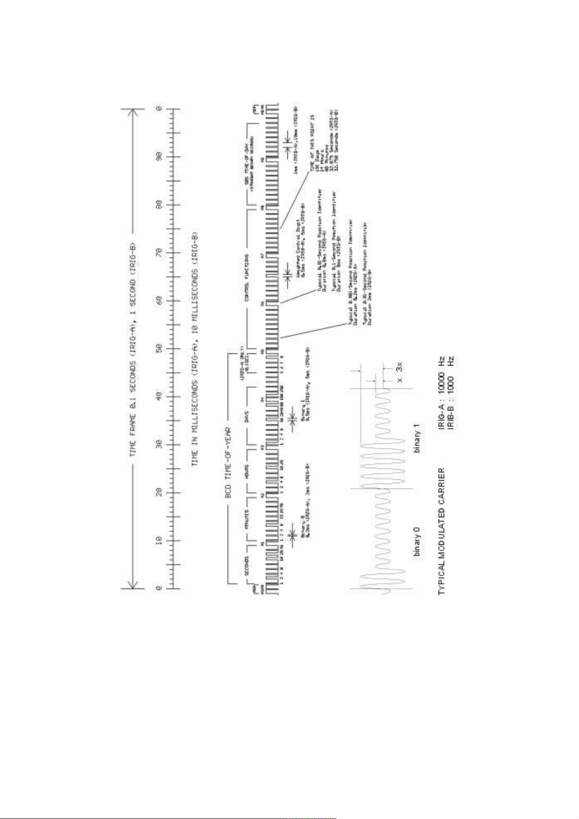
IRIG-Standard format
17
Page 18
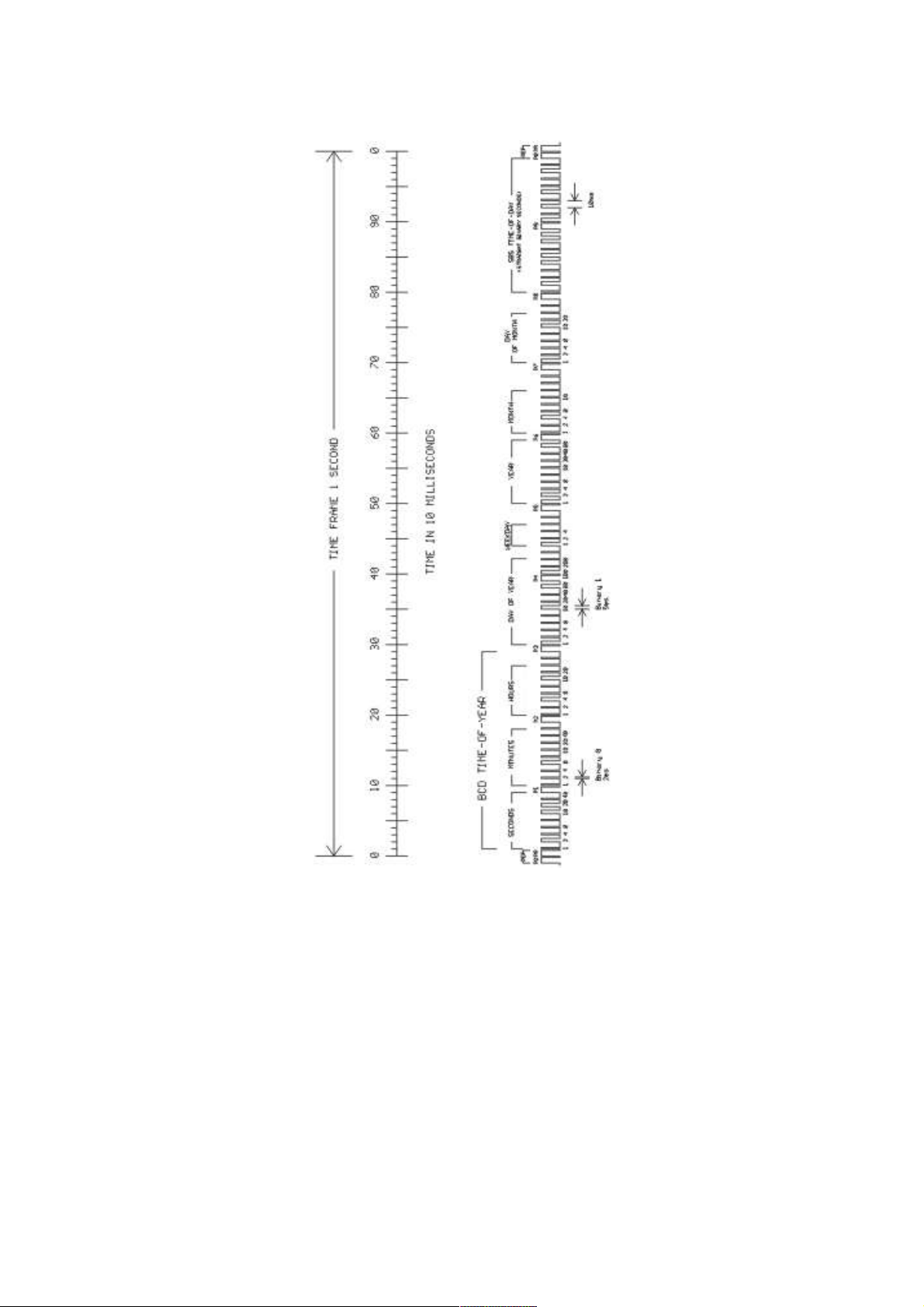
AFNOR-Standard format
Overview
The Board TCR510 was designed for the decoding of unmodulated and modulated
IRIG- and AFNOR-Timecodes. Modulated codes transport the time information by
modulating a sinusoidal carrier signals amplitude whereas unmodulated signals
employ a pulse width modulated DC signal.
The receivers automatic gain control allows the reception of signals within a range
from abt. 600mVpp up to 8Vpp. The potential free input can be jumper selectable
terminated in either 50 Ω, 600 Ω or 5 kΩ. Modulated codes are applied to the board
via an on board SMB connector.
18
Page 19

The unmodulated or 'DC Level Shift' timeocdes are applied via SUB-D connector on
rear panel. Galvanic insulation of this input is obtained by an opto coupler device.
TCR510 provides two configurable serial ports ( RS232 or 1xRS485 option ), a pulse
per minute and per second ( PPS / PPM ) as well as a DCF Simulation port at TTL
Level. Further three fixed frequency outputs at 100 kHz, 1 MHz and 10 MHz at TTL
Level are available.
Function principle
After the received IRIG-Code has passed a consistency check, the software clock and
the battery backed realtime clock of TCR510 are synchronized to the external time
reference. If an error in the IRIG-telegram is detected, the boards system clock
switches into holdover mode.
Apart from the codes AFNOR NFS 87-500 and IEEE1344, IRIG-Codes do not carry
a complete date but the number of the day within the current year ( 1...366 ). Hence
the date that is output in the serial telegram must be completed by the date stored in
the buffered real time clock. The day within the current year calculated from the
RTCs date is compared with the day number from the IRIG-Code every minute.
When a mismatch between these two day numbers is detected the board signalizes
freewheeling mode, however the systems time base will continue to synchronize with
the IRIG-signal. The DCF-Simulation is surpressed in this case.
Time and date of the real time clock can be set by a Meinberg Standard Telegram via
serial port COM0. Received IRIG-time can be re-calculated into UTC provided that
no time zone changeovers such as daylight saving appear in the received IRIGtelegrams. For more information please see chapter 'UTC-Offset' in the online
documentation of the enclosed software TCRMON.
IRIG-telegrams do not include announcers for the change of time
zone (daylight saving on/off) or for the insertion of a leap second.
Start or end of daylight saving time is executed with a delay of one
second by TCR510PCI therefore. If a leap second is inserted, the
system clock will be set to second ‘0’ for two consecutive seconds.
The board TCR510 decodes the following formats:
A133: 1000 pps, amplitude modulated sine wave signal, 10 kHz
carrier frequency
BCD time of year, SBS time of day
A132: 1000 pps, amplitude modulated sine wave signal, 10 kHz
carrier frequency
BCD time of year
A003: 1000 pps, DC Level Shift pulse width coded, no carrier
19
Page 20

BCD time of year, SBS time of day
A002: 1000 pps, DC Level Shift pulse width coded, no carrier
BCD time of year
B123: 100pps, amplitude modulated sine wave signal, 1 kHz carrier
frequency
BCD time of year, SBS time of day
B122: 100 pps, amplitude modulated sine wave signal, 1 kHz carrier
frequency
BCD time of year
B003: 100 pps,DC Level Shift pulse width coded, no carrier
BCD time of year, SBS time of day
B002: 100 pps, DC Level Shift pulse width coded, no carrier
BCD time of year
AFNOR NFS 87-500: 100 pps, amplitude modulated sine wave signal, 1 kHz carrier
frequency
BCD time of year, complete date, SBS time of day
Input Signals
Modulated IRIG or AFNOR-Codes are applied via the on board SMB connector.
The lead should be shielded. Unmodulated codes are applied at SUB-D connector on
rear panel. Voltages applied to this input shall not exceed 12 V. The IRIG-Code to be
used must be set at the DIP Switch.
Input for unmodulated codes
Unmodulated IRIG-Codes, often referred to as pulse with coded or DC-Level Shift
Codes ( DCLS ), are fed into the board via SUB-D connector on rear panel. Insulation
of this input is done by a opto coupler device. The input circuitry is shown below.
20
Page 21

Input for modulated codes
JP1 in Position 1 - 50
JP1 in Position 2 - 600
JP1 offen - ca. 5 k
Ω
Ω
Ω
Modulated codes must be applied to the on board SMB Connector. An automatic
gain control allows decoding of codes within an amplitude range from abt. 600 mVpp
up to 8 Vpp. To allow adaption of different time code generators, the boards input
impedance can be selected by an on board jumper.
Input impedance
The IRIG-specification does not define values for the output impedance of
generators or the input impedance of receivers. This fact led to incompatibility of
some modules, because the manufacturers could choose the impedances freely. For
example: if the output impedance of the generator is high and the input impedance of
the receiver low, the signal level at the receiver input might be too low for correct
decoding. Therefore the board TCR510 provides a jumper to select the impedance
(50Ω, 600 Ω or 5 kΩ) of the input for modulated codes ( SMB ) to comply with the
requirements of several systems.
Meinberg IRIG-generators have an output impedance of 50 Ω, to build a matched
transmission system when using a coaxial cable. If such a generator is used to
synchronize TCR510, the input impedance has to be set to 50 Ω accordingly (default
on delivery).
In addition to the telegram, the AFNOR-code defines the input/output impedances
also. If TCR510 is synchronized by this code, an input impedance 600 Ω of must be
set.
The setting „5 kΩ“ may be necessary if the generator has a high output impedance
(see specifications of manufacturer). The driver software shows a bar chart for
evaluation of the signal level at the receiver input.
The following detail of the placeplan of TCR510 shows the possible jumper setting
with the related input impedance:
21
Page 22

Booting the Single Board Computer
waiting for refclock on COM1
with 9600 Baud 7E2
TCR: NORMAL OPERATION Wed, 18.11.2002
NTP: Not Sync MEZ 10:04:10
TCR: NORMAL OPERATION Wed, 18.11.2002
NTP: Offset TCR: 1ms MEZ 10:04:10
The LINUX operating system is loaded from a packed file on the flash disk of the
single board computer to a RAM disk. All files of the flash disk are stored in the
RAM disk after booting. Because of that it is guaranteed that the file system is in a
defined condition after restart. This boot process takes approx. one minute. After the
LINUX system has started up already the network function is initiated and the driver
software LANTIME is started. This driver tries to get a valid time from the TCR
reference clock in order to set the LANTIMEs clock. If TCR clock is not connected
the LANTIME is waiting for a valid time.
After starting up the LINUX system the network function is initiated and the program
for communication with the TCR510 and the NTPD (NTP daemon) is started. After
that NTPD starts synchronisation with the reference clocks (usual the hardware clock
of the single board computer and the TCR). Until synchronisation is finished the
following message is displayed:
For the synchronisation of the NTPD with the TCR it is necessary that the IRIGreceiver is locked with the input signal (FAIL LED is turned off and the LOCK LED
is turned on). In this case the following message is monitored on the display:
The second line shows the user that the NTPD is synchronized with the TCR with an
offset of -1 ms. Because of the internal time of the NTP which is adjusted by a
software PLL (phase locked loop) it takes a certain time to optimise this offset. The
NTPD tries to keep the offset below ±128 ms; if the offset becomes too large the
system time is set with the IRIG-time. Typically values for the offset are +-5 ms after
the NTPD has already synchronized.
22
Page 23

Configuration User Interface
There are several ways to configure the LANTIME parameters:
Command Line Interface (CLI) via TELNET
Command Line Interface via SSH
Command Line Interface via serial interface terminal (BGT versions only)
HTTP Interface
Secure HTTP Interface (HTTPS)
Front panel LCD Interface
SNMP Management
To put LANTIME into operation for the first time an IP address is entered via the
front panel keys and LC display (refer to: DHCP IPv4 or AUTOCONF IPv6).
LANTIME variants without LC display have to be given the IP address via the serial
interface in the front panel, running a terminal software e.g. on a laptop. If once the
IPv4 address, netmask and IPv4 GATEWAY are configured, or the network interface
is initialised by IPv6 SCOPE-LINK, the LANTIME is accessible from any computer
in the network (remote).
To set up a TELNET connection the following commands are entered:
telnet 198.168.10.10 // LANTIME IP address
user: root
password: timeserver
With “setup” the configuration program is started.
To set up a SSH connection the following commands are entered:
ssh root@198.168.10.10 // LANTIME IP address
password: timeserver
With “setup” the configuration program is started.
To set up a HTTP connection the following address is to enter in a web browser:
http://198.168.10.10 // LANTIME IP address
password: timeserver
To set up a Secure HTTP (HTTPS) connection the following address is entered in a
web browser:
https://198.168.10.10 // LANTIME IP address
password: timeserver
23
Page 24

The Front Panel Layout
TCR Status LEDs
The boards state is signalised by two front panel leds. The red FAIL led indicates
the freewheeling mode. It is activated when the board has switched into freewheeling
mode, and turned off when the clock is synchronized. The green LOCK led shows the
state of the internal time base and the oscillator regulation. LOCK flashes when the
internal time base is adjusted, and is constantly turned on when the oscillator
regulation has settled. Depending on the oscillators offset the settling phase ( flashing
LOCK led ) can take a few hours.
LC Display
The 2 x 40 character LC display is used to show the receiver’s status and let the
user edit parameters. The keys described below let the user select the desired menu.
The next chapter lists all available menus in detail. A quick reference of the available
menus and submenus can be found at the end of this document.
MENU Key
This key lets the user step through several display menus showing specific data.
CLR/ACK Key
This key has to be used when parameters are to be modified. When this key is
pressed the parameters that have been edited are saved in the battery buffered
memory. If the menu is left without pressing CLR/ACK all changes are discarded.
NEXT Key
When editing parameters (LCD cursor is visible) this key moves the cursor to the
next digit with respect to the next parameter to be edited. If the current menu just
displays data (cursor not visible) pressing this key switches to a submenu (if
available).
INC Key
When editing parameters this key increments the digit or letter at the cursor
position.
24
Page 25

Configuration via LC Display
On first installation of LANTIME the network parameters can only be configured
by the front panels push buttons and the LC display. Press MENU until the SETUP
menus appear on the display. The first setup menu are the LAN PARAMETERS.
Pressing NEXT further setup menus appear. Pressing CLR/ACK the LAN
PARAMETERS menu is entered. The submenu TCP/IP ADDRESS appears. Pressing
NEXT the following submenus can be chosen: NET MASK, DEFAULT
GATEWAY, IPv6 address, HOSTNAME, DOMAINNAME, NAMESERVER and
REMOTE CONNECT. CLR/ACK lets the user enter the corresponding submenu to
make changes with NEXT and INC. Pressing CLR/ACK after changing parameters
acknowledges the changes. Leaving the menu with MENU all changes are discarded
and the setup menu is displayed again. All changed settings of the LAN
PARAMETER’s sub menu come into affect not before MENU is pressed once again
and the changes are confirmed.
The unique 32 bit TCP/IP address must be set by the network administrator. The net
mask will be defined by the network. It is probable that you will need to set up the
default gateway also.
The correct connection to the LANTIME can be reviewed from any other workstation
in the network with the program PING.
REMOTE CONNECT lets the user enable or disable all connections via network (e.g.
TELNET, FTP or HTTP). If changes occur via HTTP interface or setup program the
message “REMOTE CONNECT: partial enabled” may appear. The NTP protocol will
restart after any change.
NOTE: Any HTTP, HTTPS, SSH or TELNET connection to the LANTIME is
possible only if REMOTE CONNECT is enabled!
25
Page 26

The menus in Detail
TCR: NORMAL OPERATION Wed, 18.11.2002
NTP: Offset TCR: -1ms UTC 10:04:10
LANTIME:4.05 SN:000000000000
TCR510 :1.01 SN:9008890
NTP:4.2.0 OS:2.4.20
HWaddr: 00:00:00:00:00:00
1024 b2:a7:95:c1:fa:eb:de:9a:92:05:33:e4
:47:68:eb:91 LanV4
IRIG Receiver State: --**--*- AGC:0xFF
Drift:-00001us TFOM:0xFF SysConf:0x00
Root Menu
The root menu is shown when the receiver has completed initialisation after powerup. The left side of the first line of the display shows the receiver’s mode of operation
as described above. If the antenna is disconnected or not working properly, the text
"ANTENNA FAULTY" is displayed instead. The second line shows the offset of this
reference clock to the local time (in this example the offset is 1 ms).
On the right side of the display the current date, the name of the time zone (the time
zone is always UTC) and time are monitored. If the "SYNC Simulation" option is
enabled an "*" will be shown behind the time.
If the NEXT key is pressed from the root menu a submenu is displayed showing the
receiver’s software revision of the LANTIME software and the TCR510 flash
software:
If the NEXT key is pressed twice from the root menu a submenu is displayed showing
the NTP software version, the operating system version and the MAC address of the
integrated net card.
Pressing NEXT the third time the fingerprint of the SSH key is displayed:
Menu IRIG state
Pressing MENU in the root menu is shown when the single board computer has
completed initialisation after power-up. The first line of the display shows the system
state with 8 options described above. On the right side the AGC (Automatic Gain
Control of the input signal) value in hexadecimal will be shown. The second line will
display the drift in [us] of the internal oscillator, the TFOM value (Time Figure Of
Merit: the quality of the IRIG-signal, only used with IEEE 1344) and the current
system configuration:
26
Page 27

IRIG system state: Bit 7 ... 0
Bit 7: Invalid UTC parameter
Bit 6: TCAP exceeded, jitter out of range
Bit 5: Lock on
Bit 4: Telegramm error
Bit 3: Data available
Bit 2: Invalid sysconf
Bit 1: Pulses enabled
Bit 0: Warmed up
Invalid UTC parameter: This bit is set to one if the checksum of the ‘Offset from
UTC’ parameter, which must be used if no IEEE1344 extensions are available, is
invalid. User must enter new ‘Offset from UTC’ data to clear this bit. Please note that
the IRIG-receiver never leaves freewheeling mode if IEEE1344 is disabled and the
UTC-Parameter are invalid!
TCAP exceeded, jitter out of range: If the jitter between two consecutive IRIGtelegrams exceeds +/- 100us the receiver switches into freewheeling mode and the
‘TCAP exceeded’ Bit is set. ‘TCAP exceeded’ is cleared if the measured jitter is
below +/- 100us.
Lock on: ‘Lock On’ is set whenever the receiver is in synchronous mode and the
internal oscillator correction value has settled.
Telegram error: This bit is set if the cosistency check of two consecutive IRIGtelegrams fails. The IRIG-receiver switches into freewheling mode if ‘telegram error’
is set.
Data available: ‘data available’ is set if the receiver can read the timecode.
Invalid sysconf: If ‘invalid sysconf’ is set the checksum of the system configuration
data is invalid. In this case the default mode ‘IEEE1344 disabled’ is selected. User
must cycle the system or enter a new system configuration in the IRIG-parameter
menu.
Pulses enabled: The pulse per second (PPS) signal which increases the NTP’s
acurracy is turned when ‘lock on’ is set the first time. The ‘pulses enabled’ bit is set if
the PPS signal is enabled.
IRIG system configuration Bit 2 ... 0
Bit 7 ... 4: reserved
Bit 3: ignore Day Of Year enabled
Bit 2: ignore TFOM
Bit 1: ignore SYNC
Bit 0: IEEE 1344 enabled
27
Page 28

Menu Reference Clock State
TCR: 0000 clk_okay
filtoffset= -8.42 -4.23 -10.25
SETUP: LAN PARAMETERS
Pressing MENU in the main menu lets the user enter to the status menu of the
reference clocks. The name of the reference clock, the actual state and the last four
offsets to the NTP time are displayed (the left one is the newest).
The state of the refclock will be displayed like "0000". The first two numbers reflects
the actually state and the second two numbers the last state of the refclock. The
following states are possible:
00: clock okay
01: clock no reply
02: clock bad format
03: clock fault
04: clock bad signal
05: clock bad date
06: clock bad time
Menu SETUP
From this menu, several topics can be selected which let the user edit parameters or
force special modes of operation. A specific topic can be selected using the NEXT
key. Depending on the current topic, pressing the CLR/ACK key either enters edit
mode with the selected set of parameters or switches to the selected mode of
operation (after the user has acknowledged his decision). Once edit mode has been
entered, the NEXT key lets the cursor move to the digit or letter to be edited whereas
the INC key increments the digit or letter under the cursor. If changes have been
made, the CLR/ACK key must be pressed. If all changes have been made in one setup
submenu you have to press the MENU key. After that you will be asked to save the
settings. Press INC to change and save the last changes. Otherwise all changes are
discarded when the user presses the MENU key in order to return to the SETUP
display.
28
Page 29

SETUP LAN PARAMETERS
TCP/IP ADDRESS
000.000.000.000
SETUP: TCR PARAMETERS
Offset from UTC: +02:00
SETUP: TCR PARAMETERS
IRIG Code: B122/123
In this submenu the network parameters are configured. These parameters have to
be adapted to the existing network when the LANTIME is installed the first time. The
following parameters can be set: TCP/IP ADDRESS, NETMASK, DEFAULT
GATEWAY, IPv6 ADDRESS HOSTNAME, DOMAINNAME, NAMESERVER,
SYSLOG SERVER, SNMP MANAGER, REMOTE CONNECT, RESET
FACTORY SETTINGS und NET LINK MODE. All settings are applied to the
first Ethernet interface only. All further Ethernet interfaces have to be configured via
HTTP or CLI interface. With the submenu REMOTE CONNECT you can enable or
disable all network connections via TELNET, FTP or HTTP. When the network
parameters have been changed the configuration file is updated and the NTPD is
restarted.
With the submenu RESET FACTORY SETTINGS the following parameters will
be set to the default values:
All configuration parameters of the timeserver are saved on the Flash Disk in the file /
mnt/flash/global_configuration. It is recommended not to modify this file manually
but to use the configuration interface (HTTP, CLI or SNMP). If this file does not
exist, an empty file is generated. The default configuration file is part of the
attachment.
The parameters for speed and mode of the net card can be changed with the menu
item NET LINK MODE. There are 5 modes available: Autosensing, 10 MBit/HalfDuplex, 100 MBit/Half-Duplex, 10 MBit/Full-Duplex, 100 MBit/Full-Duplex.
Default setting is Autosensing.
SETUP TCR PARAMETERS
In this menu the parameters of the IRIG-receiver can be set. The submenu „Offset
from UTC“ lets the user set the offset from local time to UTC time. The IRIG-signal
provided no information of the offset from UTC and the receiver has to generate this
information for the NTP daemon.
With the NEXT button the menu for the used IRIG-Code will be displayed.
29
Page 30

The submenu „IGNORE SYNC“ lets the user enable or disable the IRIG SYNC
SETUP: TCR PARAMETERS
IGNORE SYNC disabled
SETUP: TCR PARAMETERS
DATE
SETUP: TCR PARAMETERS
OSCILL. ADJUST: CAL:2341 FINE:3704
SETUP: TCR PARAMETERS
Reset IRIG parameters
simulation mode. If you want to use the IRIG-receiver without connecting an IRIGsignal this mode will simulate a valid output for the NTP daemon. This is only for test
purposes. IGNORE SYNC should be disabled under normal operating conditions.
Press CLR/ACK to change the mode
The submenu „DATE“ lets the user set the date of the IRIG-receiver. If no IEEE1344
extensions are present in the connected IRIG-signal, no date information is available
from it. The item „IEEE 1344“ must be set to ‘disable’ and the user must manually
enter the current date. Press CLR/ACK to edit and to confirm the date of the IRIGreceiver. After setting the time manually the NTP daemon will be restarted
automatically.
The basic model of the TCR510 includes a voltage controlled temperature
compensated oscillator (VCTCXO). Its nominal frequency of 10 MHz is adjusted by
using two digital-to-analog converters (DACs). One of them is responsible for the
coarse tuning and the other one for the fine adjustment of the oscillator.
The value for the coarse-DAC is settable in the menu "OSCILL. AJUST" in the range
of -32768 to 32768. If the edited value exceeds the maximum value is stored. This
menu only lets the user modify the coarse-DAC (CAL). The fine-DAC (FINE) is
displayed but not to edit. It will be cleared automatically.
This value should only be changed by specialized personnel of company
Meinberg and not by the user!
The submenu „Reset IRIG parameters“ lets the user reset the IRIG-parameters to the
default values. The UTC parameters will be set to +00:00 and the system
configuration will be set to 0x00.
30
Page 31

The LANTIME configuration interfaces
The LANTIME offers three different options for configuration and status
management: Web interface, Command Line Interface Setup and SNMP. In order to
use the SNMP features of your LANTIME, you need special software like
management systems or SNMP clients. In order to use the web interface, all you need
is a web browser (LANTIME supports a broad range of browsers).
In addition to the SNMP and web interface, you can also manage your LANTIME
configuration via a command line interface (CLI), which can be used via a TELNET
or SSH connection. A setup tool can be started after login, just type “setup” and press
ENTER at the prompt.
There are only a few differences between the web interface and the CLI, most options
are accessible from both interfaces (the CLI has no statistical functions).
The above screenshots show the web interface and the Command Line Interface setup
tool. The CLI setup tool cannot be used by more than one user at a time, the web
interface can be used by more than one user in parallel, but the two or more running
sessions may influence each other. We explicitly do not recommend the parallel usage
of the configuration interfaces.
31
Page 32

The web interface
Connect to the web interface by entering the following address into the address
field of your web browser:
http://198.168.10.10
(You need to replace 198.168.10.10 with the IP address of your LANTIME). If you
want to use an encrypted connection, replace the http:// with https:// in the above
address. You may be prompted to accept the SSL certificate of your LANTIME the
first time you are connecting to the system via HTTPS.
In both HTTP and HTTPS mode, you will see the following login screen:
On this start page you see a short status display The upper line shows the operation
mode of the TCR receiver. If the connection to the IRIG-signal is lost, a “TCR: no
data available” will appear.
In the upper right corner of the display the time and time zone can be found, below
that you will find the date and weekday.
On the second line the systems reports the NTP status. During the initial
synchronisation process a “NTP: not sync” indicates that the NTP system is not
synchronised, this can also appear if the TCR510 looses synchronisation and the NTP
switches back to its “LOCAL CLOCK” time source.
The TCR510 clock is connected to the LANTIME system internally by using a serial
connection and additionally by using the second pulse. There are therefore 2 reference
clocks used by NTPD, the TCR and PPS time source. You will find the two time
sources in the status information of the NTPD. After the NTP is synchronised, the
Display shows “NTP: Offset TCR: x” or “NTP: Offset PPS: x” where “x” is the
actual offset to the TCR or PPS time source.
This page will be reloaded every 30 seconds in order to reflect the current status of
the unit. Please bear this in mind when you try to login and enter your password. If
you do not press ENTER or the Login button within 30 seconds, the user and the
password field is cleared and you have to start over again.
32
Page 33

Configuration:Main Menu
After entering the right password, the main menu page shows up. This page
contains an overview of the most important configuration and status parameters for
the system.
The start page gives a short overview of the most important configuration parameters
and the runtime statistics of the unit. In the upper left corner you can read which
LANTIME model and which version of the LANTIME software you are using. This
LANTIME software version is a head version number describing the base system and
important subsystems. Below the version you will find the actual hostname and
domain of your LANTIME unit, the IPv4 and IPv6 network address of the first
network interface and on the right side the serial number, the uptime of the system
(time since last boot) and the notification status.
In the second section the actual status of the TCR510 reference clock and the NTP
subsystem is shown, additional information about the TCR510 IRIG-receiver are also
found here. This includes the current mode of the TCR510 IRIG-receiver and the
current state.
The third section shows the last messages of the system, with a timestamp added. The
newest messages are on top of the list. This is the content of the file /
var/log/messages, which is created after every start of the system (and is lost after a
power off or reboot).
By using the buttons in the lower part of the screen, you can reach a number of
configuration pages, which are described below.
33
Page 34

Configuration: Ethernet
34
Page 35

In the network configuration all parameters related to the network interfaces can be
changed. In the first section you can change the hostname and domain name. You can
also specify two nameserver and two SYSLOG server. In the nameserver and syslog
server fields you may enter an IPv4 or IPv6 address (the syslog servers can be
specified as a hostname, too).
All information written to the LANTIME SYSLOG (/var/log/messages) can be
forwarded to one or two remote SYSLOG servers. The SYSLOG daemon of this
remote SYSLOG needs to be configured to allow remote systems to create entries. A
Linux SYSLOD can be told to do so by using the command “syslogd –r” when
starting the daemon.
If you enter nothing in the SYSLOG server fields or specify 0.0.0.0 as the SYSLOG
servers addresses, the remote SYSLOG service is not used on your LANTIME.
Please be aware of the fact that all SYSLOG entries of the timeserver are stored in /
var/log/messages and will be deleted when you power off or reboot the timeserver. A
daily CRON job is checking for the size of the LANTIME SYSLOG and deletes it
automatically, if the log size is exceeding a certain limit.
By specifying one or two remote SYSLOG servers, you can preserve the SYSLOG
information even when you need to reboot or switch off the LANTIME.
In the second section the possible network protocols and access methods can be
configured. You can enable/disable TELNET, FTP, SSH, HTTP, HTTPS, SNMP and
NETBIOS by checking/unchecking the appropriate check boxes. After you saved
your settings with the “Save” button, all these subsystems are stopped and eventually
restarted (only if they are enabled, of course).
The third section allows you to select the IP protocol version 6. In this version the
IPv4 protocol is mandatory and cannot be disabled, but as a workaround a standalone
IPv6 mode can be achieved by entering an IPv4 address “0.0.0.0” and disabling the
DHCP client option for every network interface of your LANTIME. By doing so, you
ensure that the timeserver cannot be reached with IPv4. Please note that TELNET,
FTP and NETBIOS cannot be used over IPv6 in this version. It is no problem to use
IPv4 and IPv6 in a mixed mode environment on your LANTIME.
35
Page 36

Network interface specific configuration
The interface specific parameters can be found in the Interface section. If your
LANTIME is equipped with only one network interface, you will find only one sub
section (Interface 0). Otherwise you see a sub section for each installed Ethernet port.
Here, the parameters for the network port can be changed. In the upper section of the
page you can enter the IPv4 parameters, the lower part gives you access to the IPv6
parameters of the interface.
IPv4 addresses and DHCP
IPv4 addresses are built of 32 bits, which are grouped in four octets, each
containing 8 bits. You can specify an IP address in this mask by entering four decimal
numbers, separated by a point “.”.
Example: 192.168.10.2
Additionally you can specify the IPv4 netmask and your default gateway address.
Please contact your network administrator, who can provide you with the settings
suitable for your specific network.
If there is a DHCP (Dynamic Host Configuration Protocol) server available in your
network, the LANTIME system can obtain its IPv4 settings automatically from this
server. If you want to use this feature (again, you should ask your network
administrator whether this is applicable in your network), you can change the DHCP
Client parameter to “ENABLED”. In order to activate the DHCP client functionality,
you can also enter the IP address “000.000.000.000” in the LCD menu by using the
front panel buttons of the LANTIME. Using DHCP is the default factory setting.
The MAC address of your timeserver can be read in the LCD menu by pressing the
NEXT button on the front panel twice. This value is often needed by the network
administrator when setting up the DHCP parameters for your LANTIME at the
DHCP server.
If the DHCP client has been activated, the automatically obtained parameters are
shown in the appropriate fields (IPv4 address, netmask, gateway).
IPv6 addresses and autoconf
You can specify up to three IPv6 addresses for your LANTIME timeserver.
Additionally you can switch off the IPv6 autoconf feature. IPv6 addresses are 128 bits
in length and written as a chain of 16bit numbers in hexadecimal notation, separated
with colons. A sequence of zeros can be substituted with “::” once.
36
Page 37

Examples:
"::" is the address, which simply consists of zeros
"::1" is the address, which only consists of zeros and a 1 as the
last bit. This is the so-called host local address of IPv6 and is
the equivalent to 127.0.0.1 in the IPv4 world
"fe80::0211:22FF:FE33:4455"
is a typical so-called link local address, because it uses
the “fe80” prefix.
In URLs the colon interferes with the port section, therefore IPv6IP-addresses are written in brackets in an URL.
("http://[1080::8:800:200C:417A]:80/" ; the last “:80” simply sets
the port to 80, the default http port)
If you enabled the IPv6 protocol, the LANTIME always gets a link local address in
the format “fe80:: ….”, which is based upon the MAC address of the interface. If a
IPv6 router advertiser is available in your network and if you enabled the IPv6
autoconf feature, your LANTIME will be set up with up to three link global addresses
automatically.
The last parameter in this sub section is “Netlink mode”. This controls the port speed
and duplex mode of the selected Ethernet port. Under normal circumstances, you
should leave the default setting (“autosensing”) untouched, until your network
administrator tells you to change it.
High Availability Bonding
The standard moniker for this technology is IEEE 802.3ad, although it is known by
the common names of trunking, port trunking, teaming and link aggregation. The
conventional use of bonding under Linux is an implementation of this link
aggregation.
A separate use of the same driver allows the kernel to present a single logical
interface for two physical links to two separate switches. Only one link is used at any
given time. By using media independent interface signal failure to detect when a
switch or link becomes unusable, the kernel can, transparently to user space and
application layer services, fail to the backup physical connection. Though not
common, the failure of switches, network interfaces, and cables can cause outages. As
a component of high availability planning, these bonding techniques can help reduce
the number of single points of failure.
At this menu point it is possible to add each Ethernet port to a bonding group. At least
two physical Ethernet ports must be linked to one bonding group to activate this
feature. The first Ethernet Port in one bonding group provides the IP-Address and the
net mask of this new virtual device.
37
Page 38

Additional Network Configuration
You can configure additional network parameter like special network routes or
alias definitions. For this you will edit a script file which will be activated every time
after the network configuration will run.
Also the Samba Configuration from „/etc/samba/smb.conf“ can be edited:
38
Page 39

Configuration: Notification
39
Page 40

Alarm events
On this page you can set up different notification types for a number of events. This
is an important feature because of the nature of a timeserver: running unobserved in
the background. If an error or problem occurs, the timeserver is able to notify an
administrator by using a number of different notification types.
The LANTIME timeserver offers four different ways of informing the administrator
or a responsible person about nine different events: EMAIL sends an e-mail message
to a specified e-mail account, SNMP-TRAP sends a SNMP trap to one or two SNMP
trap receivers, WINDOWS POPUP MESSAGE sends a winpopup message to one or
two different computers and DISPLAY shows the alarm message on a wall mount
display model VP100/NET, which is an optional accessory you can obtain for your
LANTIME.
Here is a table of supported events:
"NTP not sync" NTP is not synchronised to a reference time source
"NTP stopped" NTP has been stopped (mostly when very large time offsets
occur)
"Server boot" System has been restarted
"Receiver not responding" No contact to the internal TCR510 receiver
"Receiver not sync" Internal TCR510 clock is not synchronised to IRIG-signal
"no IRIG signal" TCR510 no IRIG-signal detected
"IRIG signal detected" TCR510 IRIG-signal detected
"Config changed" Configuration was changed by a user
Every event can use a combination of those four notification types, of course you can
disable notification for an event (by just disabling all notification types for this event).
The configuration of the four notification types can be changed in the upper section of
the page, you can control which notification is used for which event in the lower part
of the page.
E-mail messages
You can specify the e-mail address which is used as the senders address of the
notification e-mail (From: address), the e-mail address of the receiver (To: address)
and a SMTP smarthost, that is a mail server forwarding your mail to the receiver’s
mail server. If your LANTIME system is connected to the internet, it can deliver
those e-mails itself by directly connecting to the receivers mail server.
These settings can not be altered with the LC display buttons of the front panel.
Please note the following:
- The LANTIME hostname and domain name should be known to the SMTP
smarthost
- A valid nameserver entry is needed
- The domain part of the “From:” address has to be valid
40
Page 41

Windows Popup Messages
Most Microsoft Windows operating systems provide you with a local notification
tool. You can send messages via the special Windows protocol in your local network.
It is not necessary to enable the NETBIOS protocol of the LANTIME in order to use
this notification. On the Windows client side it is necessary to activate the “Microsoft
Client for Windows” in the network configuration.
You can enter the Windows computer name of up to two Windows PCs in the
appropriate fields. Every message contains a time stamp and a plain text message:
SNMP-TRAP messages
Up to two SNMP trap receiver hosts can be configured in this subsection, you may
use IPv4 or IPv6 addresses or specify a hostname. Additionally you have to enter a
valid SNMP community string for your trap receiving community. These can be
unrelated to the SNMP community strings used for status monitoring and
configuration access (see SNMP configuration on the “Security” page).
VP100/NET wall mount display
The VP100/NET wall display is an optional accessory for the LANTIME
timeserver, it has an own integrated Ethernet port (10/100 Mbit) and a SNTP client.
The time for the display can be received from any NTP server using the SNTP
protocol (like your LANTIME), additionally the display is capable of showing text
messages, which are sent by using a special utility. The LANTIME can send an alarm
message to one or two VP100/NET displays over the network, whenever an event
occurs for which you selected the display notification type. If this happens, a scrolling
alarm message is shown three times on the display.
Just enter the display’s IP address and its serial number (this is used for
authorisation), which can be found by pressing the SET button on the back of the
display four times. The serial number consists of 8 characters, representing four bytes
in hexadecimal notation.
If you want to use the display for other purposes, you can send text messages to it by
using our command line tool send2display, which can be found on the LANTIME.
This allows you to use the display by CRON jobs or your own shell scripts etc. If you
run the tool without parameters, a short usage screen is shown, explaining all
parameters it may understand. See appendix for a printout of this usage screen.
41
Page 42

User defined Alarm scripts
You can define your own alarm script for every event by using the “Edit user
defined notification script”. This script will be called automatically if one of the
selected events occurs. This user alarm script will be stored on the Flash-Disk at
“/mnt/flash/user_defined_notification”. This script will be called with index and the
alarm message as text. The index value of the test message is 0.
Alarm messages
You can change the alarm message text for every event by using the „Edit
Messages“ button, the messages are stored in a file /mnt/flash/notification_messages
on the flash disk of your timeserver.
42
Page 43

Configuration: Security
43
Page 44

Password
On the ““Security““ page you can manage all security relevant parameters for your
timeserver. In the first section “Login” the administration password can be changed,
which is used for SSH, TELNET, FTP, HTTP and HTTPS access. The password is
stored encrypted on the internal flash disk and can only be reset to the default value
“timeserver” by a “factory reset”, changing all settings back to the factory defaults.
Please refer to the LCD configuration section in this manual.
HTTP Access Control
With this function you can restrict the access to the web interface and allow only a
few hosts to login. Only the hosts you entered in the list are able to login to the
HTTP/HTTPS server of your LANTIME.
If a non-allowed host tries to login, the following message appears:
44
Page 45

SSH Secure Shell Login
The SSH provides you with a secure shell access to your timeserver. The
connection is encrypted, so no readable passwords are transmitted over your network.
The actual LANTIME version supports SSH1 and SSH2 over IPv4 and IPv6. In order
to use this feature, you have to enable the SSHD subsystem and a security key has to
be generated on the timeserver by using the “Generate SSH key” button. Afterwards,
a SSH client can connect to the timeserver and opens a secure shell:
ssh root @ 192.168.16.111
The first time you connect to a SSH server with an unknown certificate, you have to
accept the certificate, afterwards you are prompted for your password (which is
configured in the first section of this page).
If you generate a new SSH key, you can copy and paste it into your SSH client
configuration afterwards in order to allow you to login without being prompted for a
password. We strongly recommend to use SSH for shell access, TELNET is a very
insecure protocol (transmitting passwords in plain text over your network).
If you enabled SSH, your LANTIME automatically is able to use secure file transfer
with SCP or SFTP protocol. The usage of FTP as a file transfer protocol is as insecure
as using TELNET for shell access.
45
Page 46

Generate SSL Certificate for HTTPS
HTTPS is the standard for encrypted transmission of data between web browser
and web server. It relies on X.509 certificates and asymmetric crypto procedures. The
timeserver uses these certificates to authenticate itself to the client (web browser).
The first time a web browser connects to the HTTPS web server of your LANTIME,
you are asked to accept the certificate of the web server. To make sure that you are
talking to your known timeserver, check the certificate and accept it, if it matches the
one stored on the LANTIME. All further connections are comparing the certificate
with this one, which is saved in your web browser configuration. Afterwards you are
prompted to verify the certificate only when it changed.
By using the button ““Generate SSL certificate for HTTP““ you can create a new
certificate. Please enter your organisation, name, mail address and the location in the
upcoming form and press “Generate SSL certificate” to finally generate it.
After the successful generation of the certificate, it is shown to you:
It is also possible to upload your own HTTPS certification. If you upload a non valid
certification HTTPS will not work.
46
Page 47

NTP keys and certificates
The fourth and fifth section of the “Security“ page allow you to create the needed
crypto keys and certificates for secure NTP operation (please see NTP authentication
below).
The function “Generate new NTP public key“ is creating a new self-signed certificate
for the timeserver, which is automatically marked as “trusted“.
Important note: This certificate is depending on the hostname of your LANTIME, it
is mandatory to re-create the certificate after changing the hostname. The certificates
are build with the internal command “ntp-keygen -T” (ntp-keygen is part of the in-
stalled NTP suite). Your LANTIME is using the /etc/ntp/ directory for storing its
private and public keys (this is called the “keysdir”). Please refer to the chapter “NTP
Autokey” for further information (below).
The two options “Show NTP MD5 key“ and “Edit NTP MD5 keys“ allow you to
manage the symmetric keys used by NTP. More about that can be found in the
chapter about symmetric keys (below).
SNMP Parameter
In the last Section all parameters for SNMP can be configured. More information
you can find later in this manual.
47
Page 48

Configuration: NTP
The NTP configuration page is used to set up the additional NTP parameters
needed for a more specific configuration of the NTP subsystem.
The default configuration of the timeserver consists of a local clock, which represents
the hardware clock of your LANTIME system and the GPS reference clock. The local
clock is only chosen as the NTP time reference after the GPS clock lost its
synchronisation. The stratum level of this local clock is set to 12, this ensures that
clients recognise the switchover to the local clock and are able to eventually take
further actions. The local clock can be disabled if the timeserver should not answer
any more when the reference clock is out of order.
Because the reference clock is internally connected to the LANTIME system by using
a serial connection, the accuracy using this way of synchronisation is around 1 ms.
The high accuracy of the LANTIME timeserver (around 10 microseconds) is
available by using the ATOM driver of the NTP subsystem, which is directly
48
Page 49

interpreting the PPS (pulse per second) of the GPS reference clock. The default
configuration looks like this:
# *** lantime ***
# NTP.CONF for GPS167 with UNI ERLANGEN
server 127.127.1.0 # local clock
fudge 127.127.1.0 stratum 12 # local stratum
server 127.127.8.0 mode 135 prefer # GPS167 UNI Erlangen PPS
fudge 127.127.8.0 time1 0.0042 # relative to PPS
server 127.127.22.0 # ATOM (PPS)
fudge 127.127.22.0 flag3 1 # enable PPS API
enable stats
statsdir /var/log/
statistics loopstats
driftfile /etc/ntp.drift
# Edit /mnt/flash/ntpconf.add to add additional NTP parameters
By using the NTP configuration page, a number of additional parameters can be
added to this default ntp.conf. In the upper section up to five external NTP servers can
be set up to provide a high grade of redundancy for the internal reference clock. For
each of these external NTP servers the AUTOKEY or symmetric key feature of NTP
can be used to ensure the authentic of these time sources. The “Prefer“ flag can be set
for each external server. The internal refclock has set this flag by default. The
“Prefer“ flag is usefull if one of the refclocks are not available or out of sync.
The field “Stratum of local clock” is used to change the stratum level of the local
clock (see above), default is 12.
The “Local trusted key“ field holds a list of all trusted symmetric keys (comma or
space separated), which have to be accepted by the NTPD of your LANTIME.
If you want to use your LANTIME timeserver to send NTP broadcast packets to your
network, you have to enter a valid broadcast address in “NTP broadcast address”. If
you want to use IPv6 multicast mode, you have to enter a valid IPv6 multicast address
in this field. Please note that NTP Version 4, which is used by the LANTIME
timeserver, only permits authenticated broadcast mode. Therefore you have to set up
the AUTOKEY feature or a symmetric key if you use a NTPv4 client and want to
broadcast / multicast your time. A sample configuration of the NTP client for
broadcast with symmetric keys looks like:
broadcastclient yes
broadcastdelay 0.05 # depends on your network
keys /etc/ntp/keys
trustedkey 6 15
requestkey 15
controlkey 15
In the next section you can enable the AUTOKEY feature for your LANTIME
timeserver and the PPS mode (which is enabled in default settings), see above for a
description.
49
Page 50

The NTP Trusttime will specify the time how long the NTP will trust the reference
time if this is not synchronized (free running). This time will be set in seconds or
minutes or hours. The value 0 will be select the default value for the specific
reference clock. The default values are:
Lantime/GPS : 96 h
Lantime/PZF : 0,5 h
Lantime/RDT: 0,5 h
Lantime/NDT: 96 h
After each restart and after any change of configuration a new /etc/ntp.conf file is
generated by the LANTIME software. Any changes you made to this file are lost. In
order to use your custom ntp.conf (your LANTIME is using a standard version of the
NTP software suite, therefore all configuration parameters of the NTP software are
fully supported), you have to edit the file /mnt/flash/ntpconf.add, which is
automatically appended to the /etc/ntp.conf file generated at boot time or when
reloading configuration after a change. You can edit this file by using the button
“Edit additional NTP parameter”.
By choosing „Show current NTP configuration“, you can review the actual state of
the /etc/ntp.conf file. The file cannot be changed on this page, see above for a
description why editing this file is not reasonable.
50
Page 51

NTP Authentication
NTP version 2 and version 3 support an authentication method using symmetric
keys. If a packet is sent by the NTPD while using this authentication mode, every
packet is provided with a 32 bit key ID and a cryptographic 64/128 bit checksum of
the packet. This checksum is built with MD5 or DES, both algorithms offer a
sufficient protection against manipulation of data.
Please note that the distribution of DES in the United States of America and Canada
is subject to restrictions, while MD5 is not affected by that. With any of these
algorithms the receiving NTP clients validate the checksum. Both parties (server and
client) need to have the same crypto key with the same key ID.
In the authentication mode a party is marked “untrusted” and not suitable for
synchronisation, whenever unauthorised packets or authorised packets with a wrong
key are used. Please note that a server may recognise a lot of keys but uses only a few
of them. This allows a timeserver to serve a client, who is demanding an
authenticated time information, without “trusting” the client.
Some additional parameters are used to specify the key IDs used for validating the
authentic of each partner. The configuration file /etc/ntp.conf of a server using this
authentication mode may look like this:
# peer configuration for 128.100.100.7
# (expected to operate at stratum 2)
# fully authenticated this time
peer 128.100.49.105 key 22 # suzuki.ccie.utoronto.ca
peer 128.8.10.1 key 4 # umd1.umd.edu
peer 192.35.82.50 key 6 # lilben.tn.cornell.edu
keys /mnt/flash/ntp.keys # path for key file
trustedkey 1 2 14 15 # define trusted keys
requestkey 15 # key (mode 6) for accessing server variables
controlkey 15 # key (mode 7) for accessing server variables
The “keys“ parameter indicates the location of the file, in which all symmetric keys
are stored. The “trustedkey” line identifies all key IDs, which have to be considered
“trusted” or “uncompromised”. All other keys defined in the keyfile are considered
“compromised”. This allows to re-use already owned keys by just adding their
respective key ID to the “trustedkey” parameter. If a key needs to be “switched off”, it
can be removed from this line without actually removing it from the system. This
ensures an easy way to re-activate it later without actually transferring the key again.
The line „requestkey 15“ declares the key ID for mode-6 control messages (as
described in RFC-1305), which are used by the ntpq utility for example. The
“controlkey” parameter is specifying the key used for mode-7 private control
messages, for example used by the ntpdc utility. These keys protect the ntpd variables
against unauthorised modification.
51
Page 52

The ntp.keys file mentioned above holds a list of all keys and their respective ID
known by the server. This file should not be world-readable (only root should be able
to look into this) and it may look like this:
# ntp keys file (ntp.keys)
1 N 29233E0461ECD6AE # des key in NTP format
2 M RIrop8KPPvQvYotM # md5 key as an ASCII random string
14 M sundial # md5 key as an ASCII string
15 A sundial # des key as an ASCII string
# the following 3 keys are identical
10 A SeCReT
10 N d3e54352e5548080
10 S a7cb86a4cba80101
The first column holds the key ID (used in the ntp.conf file), the second column
defines the format of the key, which is following in column three. There are four
different key formats: “A” means DES key with up to eight 7-bit ASCII characters,
where each character is standing for a key octet (this is used by Unix passwords, too).
“S” is a DES key written in hexadecimal notation, where the lowest bit (LSB) of each
octet is used as the odd parity bit. If the key format is specified as “N”, it also consists
of a hexadecimal string, but in NTP standard format by using the highest bit (HSB) of
each octet used as the odd parity bit. A key defined as “M” is a MD5 key with up to
31 ASCII characters. The Lantime supports MD5 authentication only.
Please be aware of the following restrictions: No “#”, “\t” (tab), “\n” (newline) and
“\0” (null) are allowed in a DES or MD5 ASCII key. The key ID 0 is reserved for
special purposes and should not appear in the keys file.
52
Page 53

NTP AUTOKEY
NTP Version 4 supports symmetric keys and additionally provides the so-called
AUTOKEY feature. The authentic of received time at the NTP clients is sufficiently
ensured by the symmetric key technique. In order to achieve a higher security, e.g.
against so-called replay attacks, it is important to change the used crypto keys from
time to time.
In networks with a lot of clients, this can lead to a logistic problem, because the
server key has to be changed on every single client. To help the administrator to
reduce this work (or even eliminate it completely), the NTP developers invented the
AUTOKEY feature, which works with a combination of group keys and public keys.
All NTP clients are able to verify the authentic of the time they received from the
NTP servers of their own AUTOKEY group by using this AUTOKEY technique.
The AUTOKEY features works by creating so-called secure groups, in which NTP
servers and clients are combined. There are three different kinds of members in such a
group:
a) Trusted Host
One or more trusted NTP servers. In order to become a “trusted” server, a NTP
server must own a self-signed certificate marked as “trusted”. It is good practice to
operate the trusted hosts of a secure group at the lowest stratum level (of this group).
b) Host
One ore more NTP servers, which do not own a „trusted“ certificate, but only a
self-signed certificate without this “trusted” mark.
c) Client
One ore more NTP client systems, which in contrast to the above mentioned
servers do not provide accurate time to other systems in the secure group. They only
receive time.
All members of this group (trusted hosts, hosts and clients) have to have the same
group key. This group key is generated by a so-called trusted authority (TA) and has
to be deployed manually to all members of the group by secure means (e.g. with the
UNIX SCP command). The role of a TA can be fulfilled by one of the trusted hosts of
the group, but an external TA can be used, too.
The used public keys can be periodically re-created (there are menu functions for this
available in the web interface and also in the CLI setup program, see “Generate new
NTP public key” in section “NTP Autokey” of the “Security Management” page) and
then distributed automatically to all members of the secure group. The group key
remains unchanged, therefore the manual update process for crypto keys for the
secure group is eliminated.
53
Page 54

A LANTIME can be a trusted authority / trusted host combination and also a “nontrusted” host in such a secure group.
To configure the LANTIME as a TA / trusted host, enable the AUTOKEY feature
and initialise the group key via the HTTPS web interface (“Generate groupkey”) or
CLI setup program. In order to create such a group key, a crypto password has to be
used in order to encrypt / decrypt the certificate. This crypto password is shared
between all group members and can be entered in the web interface and CLI setup
program, too. After generating the group key, you have to distribute it to all members
of your secure group (and setup these systems to use AUTOKEY, too). In the
ntp.conf file of all group members you have to add the following lines (or change
them, if they are already included):
crypto pw cryptosecret
keysdir /etc/ntp/
In the above example “cryptosecret“ is the crypto password, that has been used to
create the group key and the public key. Please note that the crypto password is
included as a plain text password in the ntp.conf, therefore this file should not be
world-readable (only root should have read access to it).
On the clients, the server entries must be altered to enable the AUTOKEY feature for
the connections to the NTP servers of the group. This looks like:
server time.meinberg.de autokey version 4
server time2.meinberg.de
You find the server time.meinberg.de which is using the AUTOKEY feature, while
time2.meinberg.de is used without any authentic checks.
If you want to setup the LANTIME server as a trusted host, but need to use a
different trusted authority, please create your own group key with this TA and include
it with the web interface of your LANTIME (on page “Security Management” see
section “NTP autokey” , function “Upload groupkey”).
If you want to setup the LANTIME as a “non-trusted” NTP server, you have to
upload the group key of your secure group ( “Security Management” / “NTP autokey”
/ “Upload groupkey”) and create your own, self-signed certificate (without marking it
as “trusted”). Because every certificate which is creating by using the web interface
and/or CLI setup is marked “trusted”, you have to execute the tool “ntp-keygen”
manually on your LANTIME by using shell access (via SSH).
LantimeGpsV4:/etc/ntp # ntp-keygen -q cryptosecret
Here, too, “cryptosecret“ is the crypto password used in the ntp.conf entry. Then you
have to copy the new ntpkeys to the flash disk with:
cp /etc/ntp/ntpkey_* /mnt/flash/config/ntp/uploaded_groupkeys
A detailed description about ntp-keygen can be found on the NTP website
(http://www.ntp.org).
54
Page 55

Example:
This autokey group is formed by one Stratum-1-server (B), two Stratum-2-servers (D
and E) and a number of clients (in the diagram there are 4 clients shown, c1 – c4). B
is the trusted host, he holds the group key and a self-signed certificate marked as
“trusted”.
D and E are NTP servers, which are “non-trusted” hosts of the group, they hold the
group key and a self-signed certificate which lacks the “trusted” mark. The clients
also hold the group key and a self-signed certificate.
In order to distribute new public keys to the whole group, the administrator only has
to generate a new “t” key, which will be distributed automatically to the two hosts D
and E. Because these two servers can now present a unbroken chain of certificates to
a trusted host, they can be considered “trusted” by the clients as well.
More about the technical background and detailed processes of the AUTOKEY
technique can be found at the official NTP website (http://www.ntp.org).
55
Page 56

Configuration: Local
56
Page 57

Administrative functions
In the first section there are several functions which may be used by the
administrator. The button “Reboot Lantime” is restarting the system, the built-in
reference clock is not affected by this, only the included computer system is rebooted,
which may take up to 30 seconds.
With “Manual configuration“ you are able to change the main configuration by
editing the configuration file by hand. After editing, press the “Save file” button to
preserve your changes, afterwards you are asked if your changes should be activated
by reloading the configuration (this results in reloading several subsystems like
NTPD, HTTPD etc.).
The function “Send test notification“ is generating a test alarm message and sends it
using all configured notify possibilities (e-mail, WMail, SNMP-Traps, wall mount
display).
You can use the function “Save NTP drift file“ to copy the file /etc/ntp.drift to the
internal flash disc of your LANTIME. NTP is using this file to have the parameters
for compensation of the incorrectness of the system clock available directly after a
restart. This results in a faster synchronisation process of the NTPD subsystem after a
system restart. You should use this function only, if the NTPD has been synchronized
to the internal reference clock for more than one day. This is done here at Meinberg
directly before shipping the LANTIME unit to our customers, so you do not need to
use this function during normal operation. It may be applicable after a software
update.
The function “Reset to factory defaults“ is setting all configuration parameters back
to default values. The regular file /mnt/flash/global_configuration will be replaced
with the file /mnt/flash/factory.conf, but first a copy of the configuration is saved
under /mnt/flash/global_configuration.old for backup reasons. The default password
“timeserver” is replacing the actual password, too. After using this function, all
certificates should be re-created because of the change of the unit’s hostname.
57
Page 58

Please be aware of the fact that the default configuration is not activated instantly. If
you want to avoid setting up the IP address of your unit by locally configuring it on
site with the buttons of the front panel (meaning physical presence of someone
directly at the location of the LANTIME), you have to configure the network
parameters of your LANTIME immediately after using the “reset to factory defaults”
button. So, please proceed directly to the Ethernet page and check/change the IP
address and the possible access subsystems (HTTP for example) of the LANTIME.
The first usage of “Save settings” will load the configuration from flash into memory
and activate it.
The point “Download SNMP MIB files“ can be used to download all Meinberg
specific SNMP MIB files to your workstation. They can be distributed to all SNMP
management clients afterwards.
User Management
For administration different users can be set up. 3 group memberships can be
assigned to each user: the Super-User has all properties for administration. The group
membership Administrator can change all parameters via the command line interface
(CLI) configuartion tool and the WEB interface. The group Administrator cannot use
any Linux command in a Telnet, SSH or Terminal session. If the Administrator will
login, the setup program will be started directly. After termination of the Setup
program this user will be logout automatically. The group membership “Info“ has the
same properties like the Administrator but cannot change any parameter.
The menu “User Management“ allows you to set up different users with a password
and the group membership. To change the properties of an user you have to delete the
old user and set up a new one. The user “root“ cannot be deleted and has always the
membership of Super-User. The password of the user “root“ can be set on the security
page.
58
Page 59

Administrative Information
The button “List all messages“ displays the SYSLOG of the LANTIME completely.
In this log all subsystems create their entries, even the OS (upper case) kernel. The
SYSLOG file /var/log/messages is only stored in the system’s ram disk, therefore it is
lost after a power off or restart. If you configured an external SYSLOG server, all
LANTIME syslog entries will be duplicated on this remote system and can be saved
permanently this way.
Mar 15 13:35:17 LanV4 ntpd[12948]: ntpd 4.2.0@1.1161-r Fri Mar 5 15:58:48 CET
2004 (3)
Mar 15 13:35:17 LanV4 ntpd[12948]: signal_no_reset: signal 13 had flags 4000000
Mar 15 13:35:17 LanV4 ntpd[12948]: precision = 3.000 usec
Mar 15 13:35:17 LanV4 ntpd[12948]: kernel time sync status 2040
Mar 15 13:35:17 LanV4 ntpd[12948]: frequency initialized 45.212 PPM from /
etc/ntp.drift
Mar 15 13:38:36 LanV4 lantime[417]: NTP sync to TCR
Mar 15 13:38:36 LanV4 lantime[417]: NTP restart
Mar 15 13:45:36 LanV4 proftpd[14061]: connect from 172.16.3.2 (172.16.3.2)
Mar 15 14:01:11 LanV4 login[15711]: invalid password for `root' on `ttyp1' from
`172.16.3.45'
Mar 15 14:01:17 LanV4 login[15711]: root login on `ttyp1' from `172.16.3.45'
With “List detailed version information“ a number of version numbers (including
LANTIME software, operating system and NTPD) are shown in a textbox.
The function “List LANTIME Options“ shows the hardware options installed in your
LANTIME.This file contains hardware specific information which will be setup once
only by the manufacturer.
59
Page 60

Using the button “List detailed TCR information“ gives you the possibility to check
detailed TCR status information. The first parameter indicates the state of the
TCR510 clock and the state of the IRIG signal receiver. The next line will reflect
some IRIG status flags. The AGC is the automatic gain control of the internal
oscillator. The Drift will reflect the drift in micro seconds of the internal oscillator.
The last parameter will reflect the state of the internal NTP
Software Update
If you need to update the software of your LANTIME, you need a special file from
Meinberg, which can be uploaded to the LANTIME by first choosing the file on your
local computer with the “Browse” button and then press “Start firmware update”.
The chosen file will be uploaded to the LANTIME, afterwards you are prompted to
confirm the start of the update process. The scope of the update only depends on the
chosen file.
60
Page 61

Automatic configuration check
All parameters of the LANTIME can be checked for plausibility and all configured
servers (e.g. SYSLOG servers, nameservers) are tested for reachability. All red
coloured values should be reviewed by the administrator. Because all configured
hostnames / IP addresses of the servers are processed during the reachabilitytests, the
whole check process may take a while.
61
Page 62

Get Diagnostics Information
The diagnostics information is a set of configuration parameters and files stored in
a packed text file. With the help of these informations the technical support from
Meinberg can reproduce the current state of your Lantime. It takes some time to
collect all information from the Lantime. Do not press the button again while this
process is running - some web browsers will cancel the job if you press the button
twice. After that you can download the packed file “config.zip“ to your local
computer. If you have any questions or problems with your Lantime please send this
file “config.zip“ as an attachment of an e-mail to Meinberg support and describe your
problem.
Web interface language
With the selector box “Web interface language” you can change the displayed
language of the WEB interface.
62
Page 63

Configuration: Statistics
63
Page 64

Statistical Information
In the first section a graphical diagram shows the running synchronisation process.
NTP is storing this statistical information in so-called “loopstats” files, which are
used here to draw the curves. The red line is describing the offset between the internal
reference clock (GPS) and the system clock. The blue line shows the frequency errors
of the system time (in PPM, parts per million). In the upper right corner of the
diagram you will find the measurement range of the red and blue curve. The last 24
hours are shown initially, but you are able to select the last 10 days (or fewer days,
depending on the system uptime) or switch to a “merge loopstats” diagram, which
shows all available days in one diagram (with a maximum of 10 days). All time data
is using UTC.
The next sections shows version information for a number of subsystems, including
the OS kernel version, NTPD version and the GPS firmware revision of the internal
reference clock. Additionally, the MAC address of the first Ethernet interface can be
found here. The “Mem free” value is indicating the free memory available to the
system, the Disk free value is related to the ram disk of the LANTIME. Both system
memory and ram disk have a total capacity of 32 MB (each). The Uptime parameter
displays the time since the last boot process of the unit.
In the next section all NTP clients accessing the NTP server are listed. This list is
maintained internally by NTPD, clients who did not access the NTPD for a longer
period are automatically removed. This section can grow very long in large networks.
There are no further information found about the parameters “code, avglen and first.
The name resolution of the IP address in the first colume will take too much time; so
its disabled.
After that a list of all actually refclocks of the internal NTP server will be shown.
remote refid st t when poll reach delay offset jitter
================================================================================
LOCAL(0) LOCAL(0) 3 l 36 64 3 0.00 0.000 7885
lantime .GPS. 0 l 36 64 1 0.00 60.1 15875
with the following meaning:
- remote: list of all valid time servers (ntp.conf)
- refid: reference number
- st: actual stratum value (hierarchy level)
- when: last request (seconds)
- poll: period of requesting the time server (seconds)
- reach: octal notation of the successful requests, shifted left
- delay: delay of the network transmission (milliseconds)
- offset: difference between system time and reference time
(milliseconds)
- jitter: variance of the offsets (milliseconds)
The last section will show some NTP specific informations about the refclock.
64
Page 65

Configuration: Manual
This page gives you access to the documents stored on your LANTIME, especially
the manuals and your own notes. The two lists include filename, language, file type,
date and size of the documents/notes.
The LANTIME documents can be downloaded from here in order to read / print them
on your workstation.
The customer notes are a way of storing small pieces of information on your
LANTIME, for example if you want to keep track of configuration changes and want
to comment them, you can create a note called “config_changes” and show or edit it
from here. If you want to get rid of one of your notes, you are able to delete it by
choosing the appropriate button.
65
Page 66

If you want to add a note (you can maintain more than one note on your LANTIME),
after choosing the button “add note” you have to enter a filename (without a directory
path, all notes are stored in a fixed directory on the flash disk of your LANTIME) and
the language of your note first. After you confirmed these parameters with “Add
document”, you are able to edit the text of your new note.
66
Page 67

The Command Line Interface
The command line interface (CLI) can be used within a TELNET or SSH session.
After login, just enter “setup” to start the CLI setup tool.
The start page gives a short overview of the most important configuration parameters
and the runtime statistics of the unit. In the upper left corner you can read which
LANTIME type and version of the LANTIME software you are using. This
LANTIME software version is a head version number describing the base system and
important subsystem. Below the version you will find the actual hostname and
domain of your LANTIME unit, the IPv4 and IPv6 network address of the first
network interface and on the right side the serial number, the uptime of the system
(time since last boot) and the notification status is reported.
In the second section the actual status of the TCR510 IRIG-reference clock and the
NTP subsystem is shown, additional information about the IRIG-receiver can also be
found here. This includes the current state of the TCR510.
The third section shows the last messages of the system, each with a timestamp
added. The newest messages are placed at the top of the list. This reflects the content
of the file /var/log/messages, which is created after every start of the system (and is
lost after a power off or reboot, see “Syslog server” to learn how to save the entries of
your SYSLOG).
By using the buttons in the lower part of the screen, you can reach a number of
configuration pages, that are described below.
67
Page 68

CLI Ethernet
In the network configuration all parameters related to the network interfaces can be
changed. In the first section you can change the hostname and domain name. You can
also specify two nameservers and two SYSLOG servers. In the nameserver and
SYSLOG server fields you may enter an IPv4 or IPv6 address (the SYSLOG servers
can be specified as a hostname, too).
All information which is written to the LANTIME SYSLOG (/var/log/messages) can
be forwarded to one or two remote SYSLOG servers. The SYSLOG daemon of this
remote SYSLOG needs to be configured to allow remote systems to create entries. A
Linux SYSLOGD can be told to do so by using the command “syslogd –r” for
starting the daemon.
If you enter nothing in the SYSLOG server fields or specify 0.0.0.0 as the SYSLOG
server's addresses, the remote SYSLOG service is not started on your LANTIME.
Please be aware of the fact that all SYSLOG entries of the timeserver are stored in /
var/log/messages and will be deleted when you power off or reboot the timeserver. A
daily CRON job is checking for the size of the LANTIME SYSLOG and deletes them
automatically, if their size is exceeding a limit.
By specifying one or two remote SYSLOG servers, you can preserve the SYSLOG
information even when you have to reboot or switch off the LANTIME.
In the second section the possible network protocols and access methods can be
configured. You can enable/disable TELNET, FTP, SSH, HTTP, HTTPS, SNMP and
NETBIOS by checking/unchecking the appropriate check box. After you saved your
settings with the “Save” button, all of these subsystems are stopped and restarted (if
they are enabled).
The third section allows you to select the IP protocol 6. In this version the IPv4
protocol is mandatory and cannot be disabled, but a standalone IPv6 mode can be
reached by entering an IPv4 address “0.0.0.0” and disabling the DHCP client option
for every network interface of your LANTIME. By doing so, you ensure that the
timeserver cannot be reached with IPv4. Please note that TELNET, FTP and
68
Page 69

NETBIOS cannot be used over IPv6 in this version. IPv4 and IPv6 can be used
together on one LANTIME.
To manage the interface specific parameters, you can enter the Ethernet Configuration
Line page by using one of the ETHERNET buttons. If your LANTIME is equipped
with only one network interface, you will find only one button (ETHERNET 0).
Otherwise you see one button for each installed Ethernet port.
Here, the parameters for the network port can be changed. In the upper section of the
page you can enter the IPv4 parameters, the lower part gives you access to the IPv6
parameters of the interface.
IPv4 addresses are built of 32 bits, which are grouped in four octets, each containing
8 bits. You can specify an IP address in this mask by entering four decimal numbers,
separated by a point “.”.
Example: 192.168.10.2
Additionally you can specify the IPv4 Netmask and your default gateway address.
Please contact your network administrator, who will provide you with the settings
suitable for your specific network.
If you are running a DHCP (Dynamic Host Configuration Protocol) server in your
network, the LANTIME system can obtain its IPv4 settings automatically from this
server. If you want to use this feature (you should also ask your network administrator
if this is applicable in your network), you can change the DHCP Client parameter to
“ENABLED”. In order to activate the DHCP client functionality, you can also enter
the IP address “000.000.000.000” in the LCD menu by using the front panel buttons
of the LANTIME. This is the default setting.
The MAC address of your timeserver can be read in the LCD menu by pressing the
NEXT button on the front panel twice. This value is often used by the network
administrator when setting up the DHCP parameters for your LANTIME at the
DHCP server.
69
Page 70

If the DHCP client has been activated, the automatically obtained parameters are
shown in the appropriate fields (IPv4 address, netmask, gateway).
You can specify up to three IPv6 addresses for your LANTIME timeserver.
Additionally you can switch off the IPv6 AUTOCONF feature. IPv6 addresses are
128 bits in length and written as a chain of 16 bit numbers in hexadecimal notation,
separated with colons. A sequence of zeros can be substituted with “::” once.
Examples:
"::" is the address, which simply consists of zeros
"::1" is the address, which only consists of zeros and a 1 as the
last bit. This is the so-called host local address of IPv6 and is
the equivalent to 127.0.0.1 in the IPv4 world
"fe80::0211:22FF:FE33:4455"
is a typical so-called link local address, because it uses
the “fe80” prefix.
In URLs the colon interferes with the port section, therefore IPv6IP-addresses are written in brackets in an URL.
("http://[1080::8:800:200C:417A]:80/" ; the last “:80” simply sets
the port to 80, the default http port)
If you enabled the IPv6 protocol, the LANTIME always gets a link local address in
the format “fe80:: ….”, which is based upon the MAC address of the interface. If a
IPv6 router advertiser is available in your network and if you enabled the IPv6
AUTOCONF feature, your LANTIME will be set up with up to three link global
addresses automatically.
The next parameter in this sub section is “Netlink mode”. This controls the port speed
and duplex mode of the selected Ethernet port. Under normal circumstances, you
should leave the default setting (“autosensing”) untouched, until your network
administrator tells you to change it.
High Availability Bonding is the last parameter in this section. The standard moniker
for this technology is IEEE 802.3ad, although it is known by the common names of
trunking, port trunking, teaming and link aggregation. The conventional use of
bonding under Linux is an implementation of this link aggregation. A separate use of
the same driver allows the kernel to present a single logical interface for two physical
links to two separate switches. Only one link is used at any given time. By using
media independent interface signal failure to detect when a switch or link becomes
unusable, the kernel can, transparently to userspace and application layer services, fail
to the backup physical connection. Though not common, the failure of switches,
network interfaces, and cables can cause outages. As a component of high availability
planning, these bonding techniques can help reduce the number of single points of
failure.
At this menu point it is possible to add each Ethernet port to a bonding group. At least
two physical Ethernet ports must be linked to one bonding group to activate this
feature. The first Ethernet Port in one bonding group provides the IP Address and the
net mask of this new virtual device.
70
Page 71

CLI Notification
Alarm events
On this page you can set up different notification types for a number of events. This
is an important feature because of the nature of a timeserver: running in the
background. If an error or problem occurs, the timeserver is able to notify an
administrator by using a number of different notification types.
The LANTIME timeserver offers four different ways of informing the administrator
or a responsible person about nine different events: EMAIL send an e-mail message
to a specified e-mail account, SNMP-TRAP sends a SNMP trap to one or two SNMP
trap receivers, WINDOWS POPUP MESSAGE sends a Winpopup message to one or
two different computers and DISPLAY shows the alarm message on a wall mount
display model VP100/NET, that is an optional accessory you can obtain from us.
Here is a table of all events:
"NTP not sync" NTP is not synchronised to a reference time source
"NTP stopped" NTP has been stopped (mostly when very large time offsets
occur)
"Server boot" System has been restarted
"Receiver not responding" No contact to the internal TCR510 IRIG-receiver
"Receiver not sync" Internal TCR510 clock is not synchronised to IRIG-signal
"no IRIG signal detected" TCR510 no IRIG-signal detected
"Antenna reconnect" TCR510 IRIG-signal detected
"Config changed" Configuration was changed by a user
71
Page 72

Every event can use a combination of those four notification types, of course you can
disable notification for events by disabling all notification types. The configuration of
the four notification types can be changed in the upper section of the page, you can
control which notification is used for which event by using the button “notification
conditions” in the lower part of the page.
E-mail messages
You can specify the e-mail address which is used as the senders address of the
notification e-mail (From: address), the e-mail address of the receiver (To: address)
and a SMTP smarthost, that is a mail server who is forwarding your mail to the
receiver. If your LANTIME system is connected to the internet, it can deliver those emails itself.
These settings cannot be altered with the LC display buttons of the front panel. Please
note the following:
- The LANTIME hostname and domain name should be known to the SMTP
smarthost
- A valid nameserver entry is needed
- The domain part of the From: address has to be valid
72
Page 73

Windows Popup Messages
Most Microsoft Windows operating systems provide you with a local notification
tool. You can send messages via the special Windows protocol in your local network.
It is not necessary to enable the NETBIOS protocol of the LANTIME in order to use
this notification. On the Windows client side it is necessary to activate the “Microsoft
Client for Windows” in the network configuration.
You can enter the Windows computer name of up to two Windows PCs in the
appropriate fields. Every message contains a time stamp and a plain text message:
SNMP-TRAP messages
Up to two SNMP trap receiver hosts can be configured in this subsection, you may
use IPv4 or IPv6 addresses or specify a hostname. Additionally you have to enter a
valid SNMP community string for your trap receiving community. These are mostly
independent from the SNMP community strings used for status monitoring and
configuration (see SNMP configuration on the “Security” page).
VP100/NET wall mount display
The VP100/NET wall display is an optional accessory for the LANTIME
timeserver, it has an own integrated Ethernet port (10/100 Mbit) and a SNTP client.
The time of the display can be received from any NTP server using the SNTP
protocol, additionally the display is able to show text messages, which are sent by
using special software. The LANTIME can send an alarm message to one or two
VP100/NET displays over the network, whenever an event occurs, for which you
selected the display notification type. An alarm message is shown three times as a
scrolling message.
Just enter the display’s IP address and its serial number (this is used for
authorization), which can be found by pressing the red SET button on the back of the
display four times. The serial number consists of 8 characters, representing four bytes
in hexadecimal notation.
If you want to use the display for other purposes, you can send text messages to it by
using our command line tool send2display, which can be found on the LANTIME.
This allows you to use the display by CRON jobs or your own shell scripts etc. If you
run the tool without parameters, a short usage screen is shown, explaining all
parameters it may understand. See appendix for a printout of this usage screen.
73
Page 74

CLI Security
Password
On the “Security“ page you can manage all security relevant parameters for your
timeserver. In the first section “Login” the administration password can be changed,
which is used for SSH, TELNET, FTP, HTTP and HTTPS access. The password is
stored encrypted on the internal flash disk and can only be reset to the default value
“timeserver” by a “factory reset”, changing all settings back to the factory defaults.
Please refer to the LCD configuration section in this manual.
SSH Secure Shell Login
The SSH provides you with a secure shell access to your timeserver. The connection
is encrypted, so no readable passwords are transmitted over your network. The actual
LANTIME version supports SSH1 and SSH2 over IPv4 and IPv6. In order to use this
feature, you have to enable the SSHD subsystem and a security key has to be
generated on the timeserver by using the “Generate SSH key” button. Afterwards, a
SSH client can connect to the timeserver and opens a secure shell:
ssh root @ 192.168.16.111
The first time you connect to a SSH server with an unknown certificate, you have to
accept the certificate, afterwards you are prompted for your password (which is
configured in the first section of this page).
If you generate a new SSH key, you can copy and paste it into your SSH client
configuration afterwards in order to allow you to login without being prompted for a
password. We strongly recommend to use SSH for shell access, TELNET is a very
insecure protocol (transmitting passwords in plain text over your network).
74
Page 75

If you enabled SSH, your LANTIME automatically is able to use secure file transfer
with SCP or SFTP protocol. The usage of FTP as a file transfer protocol is as insecure
as using TELNET for shell access.
Generate SSL Certificate for HTTPS
HTTPS is the standard for encrypted transmission of data between web browser
and web server. It relies on X.509 certificates and asymmetric crypto procedures. The
timeserver uses these certificates to authenticate itself to the client (web browser).
The first time a web browser connects to the HTTPS web server of your LANTIME,
you are asked to accept the certificate of the web server. To make sure that you are
talking to your known timeserver, check the certificate and accept it, if it matches the
one stored on the LANTIME. All further connections are comparing the certificate
with this one, which is saved in your web browser configuration. Afterwards you are
prompted to verify the certificate only when it changed.
By using the button “Generate SSL certificate for HTTP" you can create a new
certificate. Please enter your organisation, name, mail address and the location in the
upcoming form and press “Generate SSL certificate” to finally generate it.
NTP keys and certificates
The fourth and fifth section of the “Security” page allow you to create the needed
crypto keys and certificates for secure NTP operation (please see NTP authentication
below).
The function “Generate new NTP public key“ is creating a new self-signed certificate
for the timeserver, which is automatically marked as “trusted“.
Important note: This certificate is depending on the hostname of your LANTIME, it
is mandatory to recreate the certificate after changing the hostname. The certificates
are build with the internal command “ntp-keygen -T” (ntp-keygen is part of the
installed NTP suite). Your LANTIME is using the /etc/ntp/ directory for storing its
private and public keys (this is called the “keysdir”). Please refer to the chapter “NTP
Autokey” for further information (below).
The two options “Show NTP MD5 key“ and “Edit NTP MD5 keys“ allow you to
manage the symmetric keys used by NTP. More about that can be found in the
chapter about symmetric keys (below).
75
Page 76

CLI NTP Parameter
The NTP configuration page is used to set up the additional NTP parameters
needed for a more specific configuration of the NTP subsystem.
The default configuration of the timeserver consists of a local clock, which represents
the hardware clock of your LANTIME system and the GPS reference clock. The local
clock is only chosen as the NTP time reference after the GPS clock lost its
synchronisation. The stratum level of this local clock is set to 12, this ensures that
clients recognise the switchover to the local clock and are able to eventually take
further actions. The local clock can be disabled.
Because the GPS reference clock is internally connected to the LANTIME system by
using a serial connection, the accuracy using this way of synchronisation is around 1
ms. The high accuracy of the LANTIME timeserver (around 10 microseconds) is
available by using the ATOM driver of the NTP subsystem, which is directly
interpreting the PPS (pulse per second) of the GPS reference clock. The default
configuration looks like this:
# *** lantime ***
# NTP.CONF for GPS167 with UNI ERLANGEN
server 127.127.1.0 # local clock
fudge 127.127.1.0 stratum 12 # local stratum
server 127.127.8.0 mode 135 prefer # GPS167 UNI Erlangen PPS
fudge 127.127.8.0 time1 0.0042 # relative to PPS
server 127.127.22.0 # ATOM (PPS)
fudge 127.127.22.0 flag3 1 # enable PPS API
enable stats
statsdir /var/log/
statistics loopstats
driftfile /etc/ntp.drift
# Edit /mnt/flash/ntpconf.add to add additional NTP parameters
76
Page 77

CLI NTP Authentication
Please see the corresponding chapter in the web interface description.
CLI NTP Autokey
Please see the corresponding chapter in the web interface description.
77
Page 78

CLI Local
Administrative functions
In the first section there are several functions which may be used by the
administrator. The button “Reboot LANTIME” is restarting the system, the built-in
reference clock is not affected by this, only the included computer system is rebooted,
which may take up to 30 seconds.
With “Manual configuration“ you are able to change the main configuration by
editing the configuration file by hand. After editing, press the “Save file” button to
preserve your changes, afterwards you are asked if your changes should be activated
by reloading the configuration (this results in reloading several subsystems like
NTPD, HTTPD etc.).
The function “Send test notification“ is generating a test alarm message and sends it
using all configured notify possibilities (e-mail, WMail, SNMP-Traps, wall mount
display).
You can use the function “Save NTP drift file“ to copy the file /etc/ntp.drift to the
internal flash disc of your LANTIME. NTP is using this file to have the parameters
for compensation of the incorrectness of the system clock available directly after a
restart. This results in a faster synchronisation process of the NTPD subsystem after a
system restart. You should use this function only, if the NTPD has been synchronized
to the internal reference clock for more than one day. This is done here at Meinberg
directly before shipping the LANTIME unit to our customers, so you do not need to
use this function during normal operation. It may be applicable after a software
update.
78
Page 79

The function “Reset to factory defaults“ is setting all configuration parameters back
to default values. The regular file /mnt/flash/global_configuration will be replaced
with the file /mnt/flash/factory.conf, but first a copy of the configuration is saved
under /mnt/flash/global_configuration.old for backup reasons. The default password
“timeserver” is replacing the actual password, too. After using this function, all
certificates should be recreated because of the change of the unit’s hostname.
Please be aware of the fact that the default configuration is not activated instantly. If
you want to avoid setting up the IP address of your unit by locally configuring it on
site with the buttons of the front panel (meaning physical presence of someone
directly at the location of the LANTIME), you have to configure the network
parameters of your LANTIME immediately after using the “reset to factory defaults”
button. So, please proceed directly to the Ethernet page and check/change the IP
address and the possible access subsystems (HTTP for example) of the LANTIME.
The first usage of “Save settings” will load the configuration from flash into memory
and activate it.
User Management
For administration different users can be set up. 3 group memberships can be
assigned to each user: the Super-User has all properties for administration. The group
membership Administrator can change all parameters via the command line interface
(CLI) configuartion tool and the WEB interface. The group Administrator cannot use
any Linux command in a Telnet, SSH or Terminal session. If the Administrator will
login, the setup program will be started directly. After termination of the Setup
program this user will be logout automatically. The group membership “Info“ has the
same properties like the Administrator but cannot change any parameter.
The menu “User Management“ allows you to set up different users with a password
and the group membership. To change the properties of an user you have to delete the
old user and set up a new one. The user “root“ cannot be deleted and has always the
membership of Super-User. The password of the user “root“ can be set on the security
page.
Administrative information
The button “List all messages“ displays the SYSLOG of the LANTIME
completely. In this log all subsystems create their entries, even the OS kernel. The
SYSLOG file /var/log/messages is only stored in the system’s ram disk, therefore it is
lost after a power off or restart. If you configured an external SYSLOG server, all
LANTIME SYSLOG entries will be duplicated on this remote system and can be
saved permanently this way.
Mar 15 13:35:17 LanV4 ntpd[12948]: ntpd 4.2.0@1.1161-r Fri Mar 5 15:58:48 CET
2004 (3)
Mar 15 13:35:17 LanV4 ntpd[12948]: signal_no_reset: signal 13 had flags 4000000
Mar 15 13:35:17 LanV4 ntpd[12948]: precision = 3.000 usec
Mar 15 13:35:17 LanV4 ntpd[12948]: kernel time sync status 2040
79
Page 80

Mar 15 13:35:17 LanV4 ntpd[12948]: frequency initialized 45.212 PPM from /
etc/ntp.drift
Mar 15 13:38:36 LanV4 lantime[417]: NTP sync to TCR
Mar 15 13:38:36 LanV4 lantime[417]: NTP restart
Mar 15 13:45:36 LanV4 proftpd[14061]: connect from 172.16.3.2 (172.16.3.2)
Mar 15 14:01:11 LanV4 login[15711]: invalid password for `root' on `ttyp1' from
`172.16.3.45'
Mar 15 14:01:17 LanV4 login[15711]: root login on `ttyp1' from `172.16.3.45'
With “List detailed version information“ a number of version numbers (including
LANTIME software, operating system and NTPD) are shown in a textbox.
The function “List LANTIME Options“ shows the hardware options installed in your
LANTIME.
Using the button “List detailed TCR information“ gives you the possibility to check
detailed TCR status information. The first parameter indicates the state of the
TCR510 clock and the state of the IRIG signal receiver. The next line will reflect
some IRIG status flags. The AGC is the automatic gain control of the internal
oscillator. The Drift will reflect the drift in micro seconds of the internal oscillator.
The last parameter will reflect the state of the internal NTP.
Software Update
If you need to update the software of your LANTIME, you need a special file
update.tgz from Meinberg, which has to be uploaded to the LANTIME by using ftp,
SCP or SFTP to the root dir (/update.tgz), after the file transfer is complete, press
“Start firmware update”.
Afterwards you are prompted to confirm the start of the update process. The scope of
the update only depends on the chosen file.
80
Page 81

SNMP Support
The Simple Network Management Protocol (SNMP) has been created to achieve a
standard for the management of different networks and the components of networks.
SNMP is operating on the application layer and uses different transport protocols
(like TCP/IP and UDP), so it is network hardware independent. The SNMP design
consists of two types of parties, the agent and the manager. SNMP is a client-server
architecture, where the agent represents the server and the manager represents the
client. The LANTIME has an integrated SNMP agent, who is designed especially to
handle SNMP requests for LANTIME specific status information (including status
variables for the internal reference clock). The LANTIME SNMP agent is also
capable of handling SET requests in order to manage the LANTIME configuration via
SNMP, if your SNMP management software is also supporting this feature. The
elements (objects / variables) are organised in data structures called Management
Information Base (MIB). The LANTIME includes the standard NET-SNMP MIB and
is based on SNMPv1 (RFC 1155, 1157), SNMPv2 (RFC 1901-1908) and SNMPv3.
The following SNMP version is installed on the timeserver:
Net-SNMP Version: 5.0.8
Network transport support: Callback Unix TCP UDP TCPIPv6 UDPIPv6
SNMPv3 Security Modules: usm
Agent MIB code: mibII, ucd_snmp, snmpv3mibs,
notification, target, agent_mibs, agentx
agent_mibs, utilities, meinberg, mibII/ipv6
Authentication support: MD5 SHA1
Encryption support: DES
By using the special Meinberg SNMP-agent all important status variables can be read
with SNMP conformant client software. Where applicable, a variable is implemented
as string and numeric value, for example allowing SNMP client software to use the
information for drawing diagrams or monitor threshold levels.
When using the NET-SNMP suite, you can read all status information your
LANTIME offers via SNMP by using the snmpwalk command:
snmpwalk –v2c –c public timeserver enterprises.5597
81
Page 82

...mbgLtNtp.mbgLtNtpCurrentState.0 = 1 : no good refclock (->local)
...mbgLtNtp.mbgLtNtpCurrentStateVal.0 = 1
...mbgLtNtp.mbgLtNtpStratum.0 = 12
...mbgLtNtp.mbgLtNtpActiveRefclockId.0 = 1
...mbgLtNtp.mbgLtNtpActiveRefclockName.0 = LOCAL(0)
...mbgLtNtp.mbgLtNtpActiveRefclockOffset.0 = 0.000 ms
...mbgLtNtp.mbgLtNtpActiveRefclockOffsetVal.0 = 0
...mbgLtNtp.mbgLtNtpNumberOfRefclocks.0 = 3
...mbgLtNtp.mbgLtNtpAuthKeyId.0 = 0
...mbgLtNtp.mbgLtNtpVersion.0 = 4.2.0@1.1161-r Fri Mar 5 15:58:56 CET 2004 (3)
...mbgLtRefclock.mbgLtRefClockType.0 = Clock Type: GPS167 1HE
...mbgLtRefclock.mbgLtRefClockTypeVal.0 = 1
...mbgLtRefclock.mbgLtRefClockMode.0 = Clock Mode: Normal Operation
...mbgLtRefclock.mbgLtRefClockModeVal.0 = 1
...mbgLtRefclock.mbgLtRefGpsState.0 = GPS State: sync
...mbgLtRefclock.mbgLtRefGpsStateVal.0 = 1
...mbgLtRefclock.mbgLtRefGpsPosition.0 = GPS Position: 51.9834° 9.2259° 181m
...mbgLtRefclock.mbgLtRefGpsSatellites.0 = GPS Satellites: 06/06
...mbgLtRefclock.mbgLtRefGpsSatellitesGood.0 = 6
...mbgLtRefclock.mbgLtRefGpsSatellitesInView.0 = 6
...mbgLtRefclock.mbgLtRefPzfState.0 = PZF State: N/A
...mbgLtRefclock.mbgLtRefPzfStateVal.0 = 0
...mbgLtRefclock.mbgLtRefPzfKorrelation.0 = 0
...mbgLtRefclock.mbgLtRefPzfField.0 = 0
Please note that you only see the object names (like
“mbgLtRefclock.mbgLtRefPzfField”) if you installed the Meinberg MIB files on
your client workstation first (please see the web interface or CLI setup tool chapters
to find out how to do this).
By using the standard MIB, no NTP get requests are allowed. Only the standard
system and network parameters can be accessed (e.g. using the NET-SNMP
command “snmpget”).
Only by using the Meinberg MIB the change of configuration parameters is possible
(the command “snmpset“ is used to alter a variable, for example).
82
Page 83

Configuration over SNMP
The LANTIME timeserver can be configured via several user interfaces. Besides
the possibility to setup its parameters with the web interface (HTTP and/or HTTPS)
and the direct shell access via Telnet or SSH, a SNMP based configuration interface
is available.
In order to use the SNMP configuration features of the timeserver, you need to fulfil
the following requirements (the system has to be reachable over the network, of
course):
a) SNMP has to be activated in the timeservers setup by setting up a RWCOM-
MUNITY
b) In the SNMP configuration the read-write-access needs to be activated
c) The timeserver-specific MIB files must be present on the clients, they have to be
included in the SNMP setup of the client software
a) and b) can be achieved by using the web interface or the shell access, please see the
appropriate chapters in this manual. The mentioned MIB files can be found directly
on the timeserver located at /usr/local/share/snmp/mibs. All files with names starting
with “MBG-SNMP-“ have to be copied onto the SNMP clients by using the
timeservers ftp access (for example). You may also use the web interface, on the page
“Local“ you will find a button “Download MIB files“. You will get a tar-archive if
you are using the download button, which you have to unpack first. Afterwards, copy
all MIB files to the MIB directory on your client(s) and configure your SNMP client
software to use them.
83
Page 84

Examples for the usage of the SNMP configuration features
The following examples are using the software net-snmp, a SNMP open source
project. You will find detailed information at www.net-snmp.org!
To browse the configuration branch of the timeserver-MIB, you could use the
following command on a UNIX system with net-snmp SNMP tools installed:
root@testhost:/# snmpwalk -v2c -c public timeserver.meinberg.de mbgLtCfg
MBG-SNMP-LANTIME-CFG-MIB::mbgLtCfghostname.0 = STRING: LantimeSNMPTest
MBG-SNMP-LANTIME-CFG-MIB::mbgLtCfgDomainname.0 = STRING: py.meinberg.de
MBG-SNMP-LANTIME-CFG-MIB::mbgLtCfgNameserver1.0 = STRING: 172.16.3.1
MBG-SNMP-LANTIME-CFG-MIB::mbgLtCfgNameserver2.0 = STRING:
MBG-SNMP-LANTIME-CFG-MIB::mbgLtCfgSyslogserver1.0 = STRING:
MBG-SNMP-LANTIME-CFG-MIB::mbgLtCfgSyslogserver2.0 = STRING:
[...]
To alter a parameter, with net-snmp you would use the snmpset command:
root@testhost:/# snmpset -v2c -r 0 -t 10 -c rwsecret timeserver.meinberg.de
mbgLtCfghostname.0 string „helloworld“
MBG-SNMP-LANTIME-CFG-MIB::mbgLtCfghostname.0 = STRING: helloworld
root@testhost:/#
Please note that your SNMP request has to be sent with a sufficient timeout (in the
above snmpset example this was achieved by using the “-t 10“ option, choosing a
timeout of 10 seconds), because after each parameter change, the timeserver reloads
its configuration, which takes a few seconds. The request is acknowledged by the
SNMP agent afterwards.
To change a group of parameters without reloading the configuration after each
parameter, you have to send all parameter changes in one single request. You can do
this with the net-snmp snmpset command by specifiying multiple parameters in one
command line:
root@testhost:/# snmpset -v2c -r 0 -t 10 -c rwsecret timeserver.meinberg.de
mbgLtCfghostname.0 string „helloworld“ mbgLtCfgDomainname.0 string
„internal.meinberg.de“
MBG-SNMP-LANTIME-CFG-MIB::mbgLtCfghostname.0 = STRING: helloworld
MBG-SNMP-LANTIME-CFG-MIB::mbgLtCfgDomainname.0 = STRING: internal.meinberg.de
root@testhost:/#
The available SNMP variables are described in detail in the “SNMP configuration
reference“ part of this manual. Additionally, it is recommended to also read the
mentioned MIB files.
84
Page 85

Further configuration possibilities
Because the timeserver uses a standard version of the net-snmp SNMP daemon
(with extended features covering the timeserver-specific functions), all configuration
parameters of the SNMPD can be used. The configuration file of the SNMP daemon
is located at /usr/local/share/snmp after boot time, the filename is snmpd.conf.
During the boot sequence, this file is created dynamically by using a template file and
appending the SNMP parameters stored in the timeserver setup.
If you need to customize the configuration of the timeservers SNMPD (for setting up
detailed access control rights for example), you may edit
/mnt/flash/packages/snmp/etc/snmpd_conf.default (which is the mentioned template
file). Please note that some lines are appended to this file (as described above), before
it is used as /usr/local/share/snmp/snmpd.conf by the snmpd process.
Send special timeserver commands with SNMP
The timeserver is capable of receiving special commands by SNMP in order to
reboot the unit or reload its configuration after you manually changed it. A special
SNMP variable is reserved for this (mbgLtCmdExecute) and has to be set to a special
integer value for each command. The following commands are available:
Reboot(1)
Setting the mbgLtCmdExecute variable to value 1 will reboot the timeserver after a
short waiting period of approximately 3-5 seconds.
FirmwareUpdate(2)
This command installs a previously uploaded (with FTP for example) firmware
version.
ReloadConfig(3)
The parameters of the timeserver configuration (stored in
/mnt/flash/global_configuration) are re-read and afterwards a number of subsystems
(e.g. NTPD, HTTPD/HTTPSD, SMBD) will be restarted in order to use those
eventually changed settings. Please note that the SNMPD will not be restarted by this
command (you have to use reboot instead or restart it manually by killing the process
and starting it again in the shell).
GenerateSSHKey(4)
A new SSH key will be generated.
85
Page 86

GenerateHTTPSKey(5)
A new HTTPS key will be generated.
ResetFactoryDefaults(6)
The configuration of the timeserver is reset to factory defaults, afterwards an
automatic ReloadConfig is executed in order to use these default settings.
GenerateNewNTPAutokeyCert(7)
A new key is generated, it can be used with the NTP AUTOKEY feature.
SendTestNotification(8)
A test message is sent by using all notification methods the timeserver has a
configuration for (e.g. mail, winpopup, SYSLOG etc.).
A few examples:
(we are again using the snmpset command which comes with the net-snmp tools).
root@testhost:/# snmpset -v2c -r 0 -t 10 -c rwsecret timeserver.meinberg.de
mbgLtCmdExecute.0 int 1
MBG-SNMP-LANTIME-CMD-MIB::mbgLtCmdExecute.0 = INTEGER: Reboot(1)
root@testhost:/#
The command shown above is forcing the timeserver to reboot. Instead of using the
integer value, you may also enter the command name, as it is defined in the MIB file
MBG-SNMP-LANTIME-CMD.txt (and in the command list above).
If you want the timeserver to reload it's configuration file (which you previously
uploaded via FTP probably), you would enter this command:
root@testhost:/# snmpset -v2c -r 0 -t 10 -c rwsecret timeserver.meinberg.de
mbgLtCmdExecute.0 int ReloadConfig
MBG-SNMP-LANTIME-CMD-MIB::mbgLtCmdExecute.0 = INTEGER: ReloadConfig(3)
root@testhost:/#
Please pay attention to the options “-r 0“ (meaning “no retries“) and “-t 10“ (meaning
“timeout of 10 secs“) in the above examples. These options avoid multiple executions
of the desired command, additionally they give your snmpset command enough time
to wait for an acknowledgement from the timeservers snmp agent.
86
Page 87

Configuration of the timeserver with SNMP: Reference
The MIB of the timeserver includes the following parts:
SNMP Object Name Description
enterprises.5597 mbgSNMP Root node of the Meinberg-MIB
mbgSNMP.3 mbgLantime Root node of the LANTIME MIB
mbgLantime.1 mbgLtNtp LANTIME NTP status variables
mbgLantime.2 mbgLtRefclock LANTIME reference time source status
variables
mbgLantime.3 mbgLtTraps LANTIME SNMP traps
mbgLantime.4 mbgLtCfg LANTIME configuration variables
mbgLantime.5 mbgLtCmd LANTIME control commands
Further detailed information can be found in the Meinberg MIB files.
Reference of LANTIME SNMP configuration variables:
SNMP branch Variable Data type Description
mbgLtCfgNetwork mbgLtCfghostname string The hostname of the timeserver
mbgLtCfgNTP mbgLtCfgNtpServer1IP string (IPv4 or IPv6-
mbgLtCfgDomainname string The Domainname of the timeserver
mbgLtCfgNameserver1 string (IPv4 or IPv6-
address)
mbgLtCfgNameserver2 string (IPv4 or IPv6-
address)
mbgLtCfgSyslogserver1 string (IPv4 or IPv6-
address or
hostname)
mbgLtCfgSyslogserver2 string (IPv4 or IPv6-
address or
hostname)
mbgLtCfgTelnetAccess integer (0 =
disabled, 1 =
enabled)
mbgLtCfgFTPAccess integer (0 =
disabled, 1 =
enabled)
mbgLtCfgHTTPAccess integer (0 =
disabled, 1 =
enabled)
mbgLtCfgHTTPSAccess integer (0 =
disabled, 1 =
enabled)
mbgLtCfgSNMPAccess integer (0 =
disabled, 1 =
enabled)
mbgLtCfgSambaAccess integer (0 =
disabled, 1 =
enabled)
mbgLtCfgIPv6Access integer (0 =
disabled, 1 =
enabled)
mbgLtCfgSSHAccess integer (0 =
disabled, 1 =
enabled)
address or
hostname)
mbgLtCfgNtpServer1KEY integer Link to the key which should be used
mbgLtCfgNtpServer2IP string (IPv4 or IPv6-
address or
hostname)
mbgLtCfgNtpServer2KEY integer Link to the key which should be used
mbgLtCfgNtpServer3IP string (IPv4 or IPv6-
address or
hostname)
IP-address of first nameserver
IP-address of second nameserver
IP-address or hostname of first syslogserver
IP-address or hostname of second
syslog-server
Telnet access activated?
FTP-access activated?
Webinterface activated?
Encrypted webinterface activated?
SNMP-daemon activated?
LANManager-access activated?
IPv6-protocol enabled?
SSH-access activated?
First external NTP-server
for the first NTP-server
Second external NTP-server
for the second NTP-server
Third external NTP-server
87
Page 88

SNMP branch Variable Data type Description
mbgLtCfgEMail mbgLtCfgEMailTo string (Liste von
mbgLtCfgSNMP mbgLtCfgSNMPTrapReceiver1 string (IPv4 or IPv6-
mbgLtCfgWinpopup mbgLtCfgWMailAddress1 string First receiver of notifications sent as
mbgLtCfgWalldisplay mbgLtCfgVP100Display1IP string (IPv4 or IPv6-
mbgLtCfgNtpServer3KEY integer Link to the key which should be used
mbgLtCfgStratumLocalClock integer(0..15) Stratum-value of the internal system
mbgLtCfgNTPTrustedKey integer Link to the key which should be used
mbgLtCfgNTPBroadcastIP string (IPv4 or IPv6-
mbgLtCfgNTPBroadcastKey integer Link to the key which should be used
mbgLtCfgNTPBroadcastAutokey integer (0 =
mbgLtCfgAutokeyFeature integer (0 =
mbgLtCfgAtomPPS integer (0 =
mbgLtCfgEMailFrom string (EMail-
mbgLtCfgEMailSmarthost string (IPv4 or IPv6-
mbgLtCfgSNMPTrapReceiver1Commu
nity
mbgLtCfgSNMPTrapReceiver2 string (IPv4 or IPv6-
mbgLtCfgSNMPTrapReceiver2Commu
nity
mbgLtCfgSNMPROCommunity string The SNMP community, which has read-
mbgLtCfgSNMPRWCommunity string The SNMP community, which has read-
mbgLtCfgSNMPContact string Contact information (e.g. name of a
mbgLtCfgSNMPLocation string Location (e.g. building/room number) of
mbgLtCfgWMailAddress2 string Second receiver of notifications sent as
mbgLtCfgVP100Display1SN string (Hexstring) The serial number of the first wall
mbgLtCfgVP100Display2IP string (IPv4 or IPv6-
mbgLtCfgVP100Display2SN string (Hexstring) The serial number of the first wall
address)
disabled, 1 =
enabled)
disabled, 1 =
enabled)
disabled, 1 =
enabled)
EMail-addressn)
address)
address or
hostname)
address or
hostname)
string The SNMP community used when
address or
hostname)
string The SNMP community used when
address or
hostname)
address or
hostname)
for the third NTP-server
clock of the timeserver
for the internal reference time source
IP-address, which has to be used for
NTP-broadcasts (or multicasts)
for outgoing NTP-broadcasts
Use autokey for NTP broadcasts?
Use autokey feature of the NTP server?
Atom PPS (pulse per second) activated?
One or more (semicolon separated)
email address(es). which should receive
warnings and alarm notifications from
the timeserver
The EMail-address which is used as the
senders address for email notifcations
The SMTP-host, which is used for
sending mails
First host, which receives notifications
sent as SMTP-traps
sending SNMP-Traps to the first host
Second host, which receives
notifications sent as SMTP-traps
sending SNMP-Traps to the second host
only access and therefore can be used to
only monitor status variables or
configuration values (SNMP V2c)
write access and there for can be used to
monitor status variables and get/set
configuration values (SNMP V2c)
contact person) of the timeserver
the timeserver
windows popup messages
windows popup messages
hostname or IP-address of the first
wallmount display used for showing
notifications
mount display used for showing
notifications (can be found in the setup
menu of the display)
hostname or IP-address of the second
wall mount display used for showing
notifications
mount display used for showing
notifications (can be found in the setup
menu of the display)
88
Page 89

SNMP branch Variable Data type Description
mbgLtCfgNotify mbgLtCfgNotifyNTPNotSync
mbgLtCfgNotifyNTPStopped string (combination) (see mbgLtCfgNotifyNTPNotSync) for
mbgLtCfgNotifyServerBoot
mbgLtCfgNotifyRefclockNotR
esponding
mbgLtCfgNotifyRefclockNotSy
nc
mbgLtCfgNotifyAntennaFaulty
mbgLtCfgNotifyAntennaRecon
nect
mbgLtCfgNotifyConfigChange
d
mbgLtCfgNotifyLeapSecondAn
nounced
mbgLtCfgEthernet mbgLtCfgEthernetIf0IPv4IP
mbgLtCfgEthernetIf0IPv4Netm
ask
mbgLtCfgEthernetIf0IPv4Gate
way
mbgLtCfgEthernetIf0DHCPCli
ent
mbgLtCfgEthernetIf0IPv6IP1 string (IPv6 IP-
mbgLtCfgEthernetIf0IPv6IP2 string (IPv6 IP-
mbgLtCfgEthernetIf0IPv6IP3 string (IPv6 IP-
mbgLtCfgEthernetIf0IPv6Auto
conf
mbgLtCfgEthernetIf0NetlinkM
ode
string(combination)
string (combination) (see mbgLtCfgNotifyNTPNotSync) for
string (combination) (see mbgLtCfgNotifyNTPNotSync) for
string (combination) (see mbgLtCfgNotifyNTPNotSync) for
string (combination) (see mbgLtCfgNotifyNTPNotSync) for
string (combination) (see mbgLtCfgNotifyNTPNotSync) for
string (combination) (see mbgLtCfgNotifyNTPNotSync) for
string (combination) (see mbgLtCfgNotifyNTPNotSync) for
string (IPv4 IPaddress)
string (IPv4
Netzmaske)
string (IPv4 IPaddress)
integer (0 =
disabled, 1 =
enabled)
address)
address)
address)
integer (0 =
disabled, 1 =
enabled)
integer (0..4)
Exactly one, none or a combination of
the following notification types:
email=sending an email
wmail=sending a winpopup-message
snmp=sending a SNMP-trap,
disp=showing on wall mount display,
syslog=sending a syslog-entry
for the event „NTP not synchronized“
the event „NTP Daemon stopped“
the event „Timeserver reboot“
the event „Refclock not ready“
the event „Refclock not synchron“
the event „GPS antenna not connected or
dammaged“
the event „GPS antenna reconnected“
the event „Configuration changed“
the event „Leap second announced“
IPv4-address of first network interface
of the timeserver
IPv4-netmask of first network interface
of the timeserver
IPv4-address of the default gateway of
the timeservers first network interface
Configure the first network interface of
the timeserver with DHCP?
First IPv6-IP-address of the timeservers
first network interface
Second IPv6-IP-address of the
timeservers first network interface
Third IPv6-IP-address of the timeservers
first network interface
Activate autoconf for the IPv6 configuration of the timeservers first
network interface?
Configuration of the network-speed and
duplex settings of the timeservers first
network interface
0 = autosensing,
1 = 10Mbit/s half duplex,
2= 10Mbit/s full duplex,
3=100Mbit/s half duplex,
4=100Mbit/s full duplex
For all additional Ethernet interfaces of the timeserver, “If0“ only has to be replaced
with “Ifx“, where “x“ is substituted by the number of the desired Ethernet interface.
Example: The IPv4-address of the timeservers third Ethernet interface can be set with
mbgLtCfgEthernetIf2IPv4IP!
89
Page 90

SNMP Traps
If configured, the LANTIME is sending SNMP traps, which can be received by up
to 2 SNMP management systems. These traps can be received by using the NETSNMP suite tool “snmptrapd”, you can start it on a UNIX system with “snmptrapd –
p” (-p is for output to stdout, -s would use the syslog for output). The corresponding
MIB files can be found on the LANTIME at /usr/local/share/snmp/mibs/ , all
Meinberg specific MIB files are named “MBG-SNMP….” . These MIB files can be
downloaded by using the web interface (see “Local” page, “Download MIB files”
button), after unpacking the archive file you can import the MIB files into your
management system.
The following SNMP-traps are available:
"NTP not sync" NTP not synchronised to refclock
"NTP stopped" NTP stopped
"Server boot" System has rebooted
"Receiver not responding" no answer from GPS
"Receiver not sync" GPS receiver not synchronised
"Antenna faulty" GPS antenna not connected
"Antenna reconnect" GPS antenna reconnected
"Config changed" System parameter changed by user
„Leap second announced“ Leap second announced
See the ”Notification“ page at the web interface and Command Line Interface
description to learn how to configure the SNMP trap receivers.
90
Page 91

SNMP Trap Reference
All traps can be found under the mbgLtTraps section in the Meinberg MIB. A
special trap exists for every notification event the timeserver knows. Please note that
the traps are only sent if you configured the notification type “SNMP trap” for the
event, otherwise no trap is generated. All traps have a string parameter included,
which contains the plain text event message for the appropriate event (you are able to
change the default text messages, see web interface and/or CLI setup section to find
out how to do this).
Here is a list of all traps the timeserver knows:
mbgLtTrapNTPNotSync (mbgLtTraps.1): Whenever the NTP daemon (ntpd)
looses sync, it will generate this trap and send it to the configured SNMP trap
receivers.
mbgLtTrapNTPStopped (mbgLtTraps.2): This trap is sent when the NTP daemon
stopped, manually or because of an error condition.
mbgLtTrapServerBoot (mbgLtTraps.3): After finishing the boot process, this trap
is generated.
mbgLtTrapReceiverNotResponding (mbgLtTraps.4): Trap to be sent when the in-
ternal receiver of the timeserver is not responding.
mbgLtTrapReceiverNotSync (mbgLtTraps.5): If the internal receiver looses sync,
the SNMP trap receivers will receive this trap.
mbgLtTrapAntennaFaulty (mbgLtTraps.6): This trap will be sent whenever the
timeserver recognises a broken connection to the antenna of the receiver.
mbgLtTrapAntennaReconnect (mbgLtTraps.7): After the connection to the antenna
has been re-established, this trap is sent.
mbgLtTrapConfigChanged (mbgLtTraps 8): After reloading its configuration, the
timeserver generates this trap.
mbgLtTrapLeapSecondAnnounced (mbgLtTraps 9): If a leap second has been an-
nounced by the internal GPS receiver, this trap will be sent.
mbgLtTrapTestNotification (mbgLtTraps 99): This trap is sent whenever you are
requesting a test notification; it is only used for testing the connection between
the timeserver and your SNMP trap receivers.
91
Page 92

Attachment: Technical Information
Skilled/Service-Personnel only: Replacing the Lithium Battery
The life time of the lithium battery on the board is at least 10 years. If the need arises
to replace the battery, the following should be noted:
ATTENTION!
There is a Danger of explosion if the lithium battery is
replaced incorrectly. Only identical batteries or batteries
recommended by the manufacturer must be used for
replacement. The waste battery has to be disposed as
proposed by the manufacturer of the battery.
Technical Specifications LANTIME Multipac
HOUSING: Metal desktop case, Schroff EUROPAC lab HF
Front panel: 1U/84HP (43 mm high / 483 mm wide)
PROTECTION
RATING: IP20
PHYSICAL
DIMENSIONS: 483 mm wide x 43 mm high x 286 mm deep
92
Page 93

Safety instructions for building-in equipment
This building-in equipment has been designed and tested in accordance with the
requirements of Standard IEC 950 "Safety of Information Technology Equipment,
including Electrical Business Equipment".
During installation of the building-in equipment in an end application (i.e. rack)
additional requirements in accordance with Standard IEC 950 have to be taken into
account.
o The building-in equipment is a class 1 - equipment and must be connected to an
earthed outlet (TN Power System).
o The building-in equipment has been evaluated for use in office environment
(pollution degree 2) and may be only used in this environment. For use in
rooms with a higher pollution degree more stringent requirements are
applicable.
o The building-in equipment may not be opened.
o Protection against fire must be assured in the end application.
o The ventilation opening may not be covered.
o The equipment/building-in equipment was evaluated for use in a maximum
ambient temperature of 40 °C.
o For safe operation the building-in equipment must be protected by max 16 A
fuse in the power installation system.
o Disconnection of the equipment from mains is done by pulling the mains plug.
CE-Label
EN 60950
Safety of Information Technology Equipment,
including Electrical Business Equipment
Electromagnetic compatibility
EN50081-1
Electromagnetic compatibility (EMC). Generic emission
standard. Part 1: Residential, commercial and light industry
EN50082-2
Electromagnetic compatibility (EMC). Generic immunity
standard. Part 2: Industrial environment
93
Page 94

Rear Panel Connectors
Name Type Signal Cable
Network RJ-45 Ethernet shielded data line
Time Sync Error DFK
2 x Network RJ-45 Ethernet shielded data line
(Option)
IRIG in (mod) BNC modulated IRIG shielded coaxial line
IRIG in (unmod) BNC unmodulated IRIG shielded line
Power supply power cord receptacle 95-240V AC ±10 % power supply cord
EN60320 – C13
94
Page 95

Rear View LANTIME
95
Page 96

Technical Specifications TCR510
RECEIVER INPUT: AM INPUT ( SMB-Connector ):
Insulated by transformer
Impedance: 50 Ω, 600 Ω, 5 kΩ selectable by
jumper
Input signal: abt.600 mVpp to 8 V (Mark)
other ranges on request
DC-Level Shift Input ( VG-Connector ):
Insulated by opto-coupler device
Internal series resistor: 330 Ω
Max. input current: 25 mA
Diode forward voltage:1.0 V...1.3 V
DECODING: Decoding of the following codes possible :
IRIG-A133/A132/A003/A002
IRIG-B123/B122/B003/B002
AFNOR NFS 87-500
ACCURACY OF TIME BASE : +/- 10us compared to IRIG reference marker
REQUIRED ACCURACY OF
TIME CODE SOURCE : +/- 100ppm
HOLDOVER MODE: Automatic switching to crystal time base,
accuracy : see. accuracy of Oscillator
BACKUP BATTERY : Onboard realtime clock keeps time and date
in case of power supply failure. System
parameters are stored in battery buffered ram
Lifetime of Lithium battery at least 10 years
RELIABILITY OF
OPERATION: Microprocessor supervisory circuit generates
reset in case of brown-out, software watchdog
generates reset in case of improper program
execution
INITIALIZATION: Initial time and date can be set by standard
Meinberg telegram via serial port COM0
PULSE OUTPUTS: Pulse per second PPS, TTL-Level pulse, active
high, 200 ms pulse width
Pulse per minute PPM, TTL-Level pulse, active
high, 200 ms pulse width
FREQUENCY OUTPUTS: 10 MHz TTL-Level
1 MHz TTL-Level
100 kHz TTL-Level
96
Page 97

RELATIVE ACCURACY OF
FREQUENCIES COMPARED
TO IRIG SOURCE: +/- 1e-8 with TCXO-HQ option
+/- 5e-9 with OCXO-LQ option
STATUS OUTPUT: TIME_SYN, TTL LEVEL, active high when
clock is synchronuos
SERIAL PORTS: Two independent RS232 ports
BAUDRATES: 9600Bd, 19200Bd
FRAMINGS: 7E2, 8N1
OUTPUT CYCLE: Per second or per minute
SERIAL TELEGRAM: Meinberg Standard Telegram
REAR EDGE CONNECTOR: According to DIN41612, type C 64, rows a+c
( male )
POWER CONSUMPTION: VCC +5 V, abt. 300 mA
VDD +5 V, abt. 50 mA with TCXO-HQ option
Max. 500 mA OCXO-LQ/MQ
PHYSICAL DIMENSIONS: Eurocard 100 mm x 160 mm, 1,5 mm Epoxy
AMBIENT TEMPERATURE: 0...50 °C
HUMIDITY: Max. 85 %
97
Page 98

Signal description TCR510
Signal Pin Description_____________________________
VCC in (+5 V) 1a+c +5 V Voltage Supply
VDD in 3a+c Supply Voltage Oscillator
GND 32a+c Ground
31a+c
19a, 20a, 21a, 22a,
23a, 24a, 25a, 26a,
27a, 28a, 29a, 30a
P_SEC 6c Pulse per second, TTL
P_MIN 8c Pulse per minute, TTL
RESERVE 10c Reserved
DCF_MARK 17c DCF-Simulation, TTL
TIME_SYN 19c Status Output, TTL
10 Mhz 12a Freq. Output10 MHz,TTL
1 Mhz 11a Freq. Output1 MHz, TTL
100 kHz 10a Freq. Output100 kHz,TTL
UNMOD_IN+ 21c +Input unmodulated IRIG
UNMOD_IN- 22c -Input unmodulated IRIG
COM0 RxD 26c COM0 RS-232 Input
COM0 TxD 30c COM0 RS-232 Output
COM1 RxD 29c COM1 RS-232 Input
COM1 TxD 24c COM1 RS-232 Output
/BOOT 4a Boot-Input, starts bootstrap loader if hold low during
power up reset
98
Page 99

Rear Connector Pin Assignments TCR510
a c
1 VCC in (+5V) VCC in (+5V)
2
3 VDD in ( OSC ) VDD in ( OSC )
4 /BOOT
5
6 P_SEC
7
8 P_MIN
9
10 100kHz RESERVE
11 1MHz
12 10MHz
13
14
15
16
17 DCF_MARK
18
19 GND TIME_SYN
20 GND
21 GND UNMOD_IN+
22 GND UNMOD_IN-
23 GND
24 GND COM1 TxD
25 GND
26 GND COM0 TxD
27 GND
28 GND
29 GND COM1 RxD
30 GND COM0 RxD
31 GND GND
32 GND GND
DIN 41612 connector, Typ C 64, row a + c
99
Page 100

Technical Specifications LAN CPU
PROCESSOR: GeodeTM GX1 with 266 MHz
MAIN MEMORY: 32 MB (to 64 MB upgradeable)
CACHE-MEMORY: 16 KB 2nd Level Cache
FLASHDISK: 8 MB (until max. 72 MB)
NETWORK
CONNECTOR: 10/100 MBIT with RJ45-Jack
DAVICOM DM9102AEthernet NIC Controller
SERIAL INTERFACE: Four serial RS232-Ports
16550 compatible to FIFO
- RS232 9-pol. DSUB-male connector
- three RS232 male connector according to DIN 41612,
type C 96 ( only TxD, RxD, DCD)
PARALLEL
INTERFACE : One LPT-Port male connector type C 96
IDE-BUS: Primary IDE-Bus male connector type C 96
VGA-CONNECTION: 10-pol pin contact strip
KEYBOARD
CONNECTION: 10-pol pin contact strip
STATE LEDs: - power supply
- 'Connect', 'Activity' and 'Speed' of the network
connection
POWER
REQUIREMENTS: 5 V ± 5 %, @ 1 A
FRONTPANEL: 3 HE / 4 TE (128 mm high x 20,3 mm wide)
CONNECTOR: According to DIN 41612, type C 96, rows a+b+c (male)
DSUB-plug (9-pol)
RJ45-jack
AMBIENT
TEMPERATURE: 0 ... 50 °C
HUMIDITY: 85 % max.
100
 Loading...