

Page 1

Technical Information
Operating Instructions
LANTIME /
SHSPZF
ETX BGT
Page 2

Contact Information
Meinberg Funkuhren GmbH & Co. KG
Auf der Landwehr 22
D-31812 Bad Pyrmont
Telephone: +49 (0) 52 81 / 9309-0
Telefax: +49 (0) 52 81 / 9309-30
Internet: http://www.meinberg.de
E-Mail: info@meinberg.de
Bad Pyrmont, 8. November 2006
Page 3

Table of Contents
Quick Start..................................................................................................................... 8
NTP-Timeserver LANTIME/SHS.................................................................................9
The Modular System LANTIME.................................................................................12
Supported Network Services.............................................................................. 13
Additional Features and Options........................................................................ 14
User Interface..................................................................................................... 14
Options............................................................................................................... 14
Why to use a Network Timeserver.....................................................................15
Network Time Protocol (NTP).................................................................................... 15
NTP Target......................................................................................................... 16
NTP-Client Installation...................................................................................... 16
GPS satellite controlled clock......................................................................................18
GPS167 Features................................................................................................ 19
Time Zone and Daylight Saving.........................................................................19
Mounting the GPS Antenna.........................................................................................20
Assembly with CN-UB/E...................................................................................21
Antenna Short-Circuit........................................................................................ 21
General information DCF77 PZF................................................................................ 22
Features of PZF5xx..................................................................................................23
Antenna....................................................................................................................23
Assembly of antenna................................................................................................23
Powering Up the System..............................................................................................25
Booting the GPS receiver.............................................................................................25
Booting the Single Board Computer............................................................................26
Configuration User Interface....................................................................................... 27
The Front Panel Layout........................................................................................... 28
GPS FAIL LED.................................................................................................. 28
GPS LOCK LED................................................................................................ 28
LC Display......................................................................................................... 28
MENU Key.........................................................................................................28
CLR/ACK Key................................................................................................... 28
Page 4

NEXT Key..........................................................................................................28
INC Key..............................................................................................................28
Configuration via LC Display..................................................................................29
The menus in Detail................................................................................................. 30
Root Menu..........................................................................................................30
Menu SHS State................................................................................................. 31
Menu RECEIVER POS......................................................................................31
Menu SV CONSTELLATION...........................................................................32
Menu SV POSITION......................................................................................... 32
Menu SETUP..................................................................................................... 33
SETUP SHS Time Limit.................................................................................... 34
SETUP LAN PARAMETERS........................................................................... 34
SETUP PZF PARAMETERS............................................................................ 35
SETUP TIME ZONE......................................................................................... 37
SETUP DAYLIGHT SAV ON/OFF..................................................................37
SETUP SERIAL PORT......................................................................................39
SETUP SERIAL STRING TYPE...................................................................... 39
SETUP INITIAL POSITION.............................................................................40
SETUP INITIAL TIME..................................................................................... 40
IGNORE LOCK................................................................................................. 40
INITIATE COLD BOOT................................................................................... 41
INITIATE WARM BOOT................................................................................. 41
ANTENNA CABLE...........................................................................................41
Resetting Factory Defaults of the GPS...............................................................41
Front panel PZF509................................................................................................. 42
Pilot lamps..........................................................................................................42
Display................................................................................................................42
Control keys....................................................................................................... 42
PZF Menu items................................................................................................. 43
The LANTIME configuration interfaces..................................................................... 44
The web interface.........................................................................................................45
Configuration: Main Menu...................................................................................... 46
Configuration: Ethernet........................................................................................... 47
Network interface specific configuration.................................................................49
IPv4 addresses and DHCP..................................................................................49
IPv6 addresses and autoconf.............................................................................. 49
High Availability Bonding................................................................................. 50
Additional Network Configuration.....................................................................51
Configuration: Notification......................................................................................52
Alarm events.......................................................................................................53
E-mail messages................................................................................................. 53
Windows Popup Messages.................................................................................54
SNMP-TRAP messages..................................................................................... 54
VP100/NET wall mount display........................................................................ 54
Page 5

User defined Alarm scripts.................................................................................55
Alarm messages..................................................................................................55
Configuration: Security............................................................................................56
Password.............................................................................................................57
HTTP Access Control.........................................................................................57
SSH Secure Shell Login..................................................................................... 58
Generate SSL Certificate for HTTPS ................................................................ 59
NTP keys and certificates...................................................................................60
SNMP Parameter................................................................................................60
Configuration: NTP................................................................................................. 61
NTP Authentication............................................................................................64
NTP AUTOKEY................................................................................................ 66
Configuration: Local................................................................................................69
Administrative functions.................................................................................... 70
User Management...............................................................................................71
Administrative Information................................................................................ 72
Software Update................................................................................................. 74
Automatic configuration check.......................................................................... 75
Get Diagnostics Information.............................................................................. 76
Web interface language...................................................................................... 76
Configuration: Statistics.......................................................................................... 77
Statistical Information........................................................................................ 78
Configuration: Manual.............................................................................................79
The Command Line Interface...................................................................................... 81
CLI Ethernet.............................................................................................................82
CLI Notification.......................................................................................................85
Alarm events.......................................................................................................85
E-mail messages................................................................................................. 86
Windows Popup Messages.................................................................................87
SNMP-TRAP messages..................................................................................... 87
VP100/NET wall mount display........................................................................ 87
CLI Security.............................................................................................................88
Password.............................................................................................................88
SSH Secure Shell Login..................................................................................... 88
Generate SSL Certificate for HTTPS ................................................................ 89
NTP keys and certificates...................................................................................89
CLI NTP Parameter................................................................................................. 90
CLI NTP Authentication.................................................................................... 91
CLI NTP Autokey.............................................................................................. 91
CLI Local................................................................................................................. 92
Administrative functions.................................................................................... 92
User Management...............................................................................................93
Page 6

Administrative information................................................................................ 93
Software Update................................................................................................. 95
SNMP Support.............................................................................................................96
Configuration over SNMP ...................................................................................... 98
Examples for the usage of the SNMP configuration features............................ 99
Further configuration possibilities....................................................................100
Send special timeserver commands with SNMP..............................................100
Configuration of the timeserver with SNMP: Reference................................. 102
SNMP Traps...........................................................................................................105
SNMP Trap Reference..................................................................................... 106
Attachment: Technical Information...........................................................................107
Skilled/Service-Personnel only: Replacing the Lithium Battery........................... 107
Technical Specifications LANTIME BGT............................................................ 107
Safety instructions for building-in equipment....................................................... 108
CE-Label................................................................................................................ 108
Rear- / Front Panel Connectors..............................................................................109
Rear View LANTIME........................................................................................... 110
SUB-D Connector Assignments............................................................................ 111
Technical Specifications GPS167..........................................................................112
Accuracy of frequency TCXO quartz (standard)..............................................113
Technical Specifications GPS167 Antenna......................................................114
Signal Description GPS167..............................................................................115
Rear Connector Pin Assignments GPS167...................................................... 116
Technical specifications PZF5xx...........................................................................117
Signal description PZF5xx............................................................................... 119
Rear Connector Pin Assignments PZF5xx....................................................... 120
Technical Specifications LAN CPU...................................................................... 121
Rear Connector Pin Assignments LAN CPU...................................................122
VGA, Keyboard Connector Pin Assignments.................................................. 122
Technical Specifications Power Supply Unit PULS AP 336-505......................... 123
Front Panel and Rear Connector Pin Assignments...........................................123
Time Strings...........................................................................................................124
Format of the Meinberg Standard Time String................................................ 124
Format of the GPS167 Capture String............................................................. 125
Format of the SAT-Time String....................................................................... 126
Format of the Uni Erlangen String (NTP) .......................................................127
Format of the NMEA 0183 String (RMC)....................................................... 129
Page 7

Format of the ABB SPA Time String.............................................................. 130
Format of the COMPUTIME Time String....................................................... 131
Menu Quick Reference.......................................................................................... 132
Declaration of Conformity.....................................................................................133
Manual VP100/NET Display configuration.......................................................... 134
Global Configuration File...................................................................................... 136
Global Option File................................................................................................. 137
Third party software...............................................................................................138
Operating System GNU/Linux.........................................................................138
Samba............................................................................................................... 138
Network Time Protocol Version 4 (NTP)........................................................ 139
mini_httpd........................................................................................................ 139
GNU General Public License (GPL)................................................................140
Timecode (option)..................................................................................................144
Abstract.............................................................................................................144
Principle of Operation...................................................................................... 144
Block Diagram Timecode.................................................................................144
IRIG Standard Format...................................................................................... 145
AFNOR Standard Format.................................................................................146
Assignment of CF Segment in IEEE1344 Code.............................................. 147
Generated Time Codes..................................................................................... 148
Selection of Generated Time Code...................................................................148
Outputs............................................................................................................. 149
AM - Sine Wave Output...................................................................................149
PWM DC Output..............................................................................................149
Technical Data..................................................................................................149
USB Stick.............................................................................................................. 150
Menu Structure................................................................................................. 150
Menu Configuration Files................................................................................ 151
Menu Script Files............................................................................................. 152
Keypad locking.................................................................................................152
Reference............................................................................................................... 153
Page 8

Quick Start
NORMAL OPERATION
NTP: Not Ready
Tue, 05.06.2001
MESZ 14:23:03
NORMAL OPERATION
NTP: Not Sync
Tue, 05.06.2001
MESZ 12:00:00
SHS State
act.Diff: < 1ms
GPS: sync
PZF: sync
SETUP
LAN PARAMETERS
TCP/IP ADDR DHCP
0.0.0.0
SAVE SETTINGS ?
INC -> YES
MENU -> NO
- Approximately 30 seconds after power up the lower display line shows "NTP: not
sync" instead of "NTP: not ready".
==>
- When the LANTIME/SHS is switched on the SHS STATE menu is displayed
because the two receivers (GPS and PZF) are usually not synchronized yet.
After the configured time limit is reached the LANTIME/SHS goes to normal
operation. The following notes should be taken into consideration:
- The GPS antenna/converter unit must be installed in a location from which as
much of the sky as possible can be seen (see "Mounting the GPS
antenna")
- The PZF antenna must be positioned to maximize the correlation value greater
then 60 %. Also the distance to DCF77 transmitter must be configured
- The time limit (the max. accepted time difference between GPS and PZF) has to
be set to the needed accuracy (default 10 ms)
- Enter TCP/IP address, netmask and default gateway:
- Press Menu four times to enter the LAN PARAMETERS setup menu
- Press CLR/ACK to see the TCP/IP address first
- Press CLR/ACK once again to be able to enter the IPv4 TCP/IP address
- With NEXT the respective digit is to select while INC is used to set the value
- To take over the changes it is necessary to press CLR/ACK again
- A wildcard '*' is displayed to confirm the changes
- Pressing NEXT, netmask and the default gateway can be entered
- Pressing MENU following by INC causes the changes to become active
NOTE: All settings are related to the first Ethernet connection (ETH0).
After this all further settings can be done via network interface, either by using a
WEB browser or a Telnet Session.
Default user: root
Default password: timeserver
8
Page 9

NTP-Timeserver LANTIME/SHS
Secure Hybrid System with Strongly Verificated Reference Time
Meinberg LANTIME devices are Stratum-1 time servers which provide a high-
accuracy reference time to TCP/IP networks via the Network Time Protocol (NTP).
The main difference between the LANTIME models is the primary time source from
which a device derives its reference time. Primary time source options include
external radio clocks, built-in DCF77, GPS, or IRIG receivers, and even a hybrid
combination of a DCF77 and a GPS receiver.
The LANTIME/SHS/BGT (Secure Hybrid System, 19" modular case) has a built-in
hybrid radio clock which derives its reference time from both the satellite based
Global Positioning System (GPS) and long wave receiver PZF5xx. During normal
operation the hybrid radio clock passes the highly accurate reference time on to the
built-in NTP time server which makes the reference time available to the network.
In order to prevent the NTP server from spreading a faulty reference time in the
network, the hybrid receiver includes two independent standard radio clocks. Both the
satellite receiver GPS167 and the long wave receiver PZF5xx have their own signals
and high quality crystal oscillators which let the radio clocks provide accurate time
even if their primary time transmitters cannot be received for a few days.
The two radio clocks derive their time telegrams and high accuracy pulse-per-second
(PPS) signals from two independent primary time sources. The time telegrams and the
PPS signals output by the clocks are compared against each other. If either the
difference between the time telegrams or the difference between the PPS signals
exceeds a configurable limit of some milliseconds, or if one of the receivers stops
generating a time telegram, then the hybrid radio clock stops passing any timing
information to the NTP server. So the NTP server can only spread a very strongly
verificated reference time.
The radio clock modules are assembled in a 19" modular case (3UE) which also
includes a single board computer, and a power supply unit. Configurable settings can
be modified via menus on the 4 line LC display and the four buttons in the front
panel. A failure output can be used to generate an alarm signal if any malfunction is
detected.
The single board computer runs a Linux system which is loaded from flash disk into
RAM at power-up. Aside from NTP, the Linux operating system supports additional
network protocols like HTTP(S), SSH, FTP, or telnet, which allows remote
configuration or monitoring across the network, e.g. using a common web browser.
Remote access from the network can also be disabled for security reasons.
Changes in the radio clocks' receiver status, errors conditions, and other events
generate error messages which can be logged on either the local Linux system, or on
another SYSLOG server in the network. Additionally, those messages can be sent to a
management console by SNMP traps or automatic e-mails.
9
Page 10

If it is necessary to provide redundancy against hardware failure then it is also
possible to install several LANTIME NTP servers in the same network.
LANTIME/SHS: Modes Of Operation
Normal mode of operation: Both the radio clocks are synchronized to their primary
time sources, the difference between the independent reference times is below the
configured limit. The NTP server receives the time information including the status
"synchronized", so it acts as Stratum-1 server and makes the reference time available
to the network.
One of the radio clocks falls out of sync e.g. due to an antenna failure or other
reception problems. The clock changes its status to "not synchronized" and continues
counting time based on its built-in high-accuracy crystal oscillator. Depending on the
configuation, it takes some days up to several weeks until the difference between the
time signals exceeds the limit. Since one of the radio clocks is still synchronized, the
timing information is passed to the NTP server with status "synchronized" until the
limit is exceeded.
Both the radio clocks are not synchronized to their primary time sources although
at least one of them has been synchronized before. As long as the time difference
doesn't exceed the limit, the time information is passed to the NTP server, but the
status included is set to "not synchronized". The NTP server keeps accepting the time
information for a given trust time, after the trust time it discards the time information.
Both the radio clocks are not synchronized to their primary time sources and have
not been synchronized after the last power-up. The hybrid clock does not pass any
time information to the NTP server until at least one of the independent radio clocks
is synchronized and the time difference between the clocks is below the configured
limit.
The radio clocks output time information with a difference which exceeds the
configured limit, or one of the radio clocks does not output any time information
at all. One of the following circumstances can be the reason why:
An intended external fake
Failure or malfunction of one of the primary time transmitters
Failure or malfunction of one of the radio clocks
Persistent reception problems
In all the cases listed above the plausibility checks on the timing information fail,
so the hybrid radio clock stops passing any timing information on to the NTP server.
The NTP server's stratum changes to a worse value to let the clients know that the
server's reference time source fails. The hybrid radio clock continues supplying time
to the NTP server after all error conditions have been removed and the error has
been acknowledged by an operator.
10
Page 11

If one or more additional LANTIME NTP servers are available on the network then
clients which have been configured to use all of them will automatically discard the
LANTIME with the bad stratum and synchronize to another NTP server which is
operating correctly at a better stratum. If no redundant LANTIME is available,
however, the clients will continue to synchronize to the LANTIME with worse
stratum. This way it is guaranteed that all the client devices on the network operate
using the same system time.
All changes of the reception status of one of the radio clocks, and also failure of the
hybrid clock's plausibility check are logged by the local Linux system and optionally
reported across the network. If the hybrid receiver passes the status "not
synchronized" to the NTP server, or it has disabled time information output at all,
then the alarm signal output of the LANTIME/SHS is activated.
11
Page 12
The Modular System LANTIME
LANTIME is a set of equipment composed of a satellite controlled clock GPS167,
a long wave receiver PZF5xx, a single-board computer SBC GEODE 266 MHz with
integrated network card, and a power supply unit T60B, all installed in a metal
desktop case and ready to operate. The interfaces provided by LANTIME are
accessible via connectors in the rear panel of the case. Details of the components are
described below.
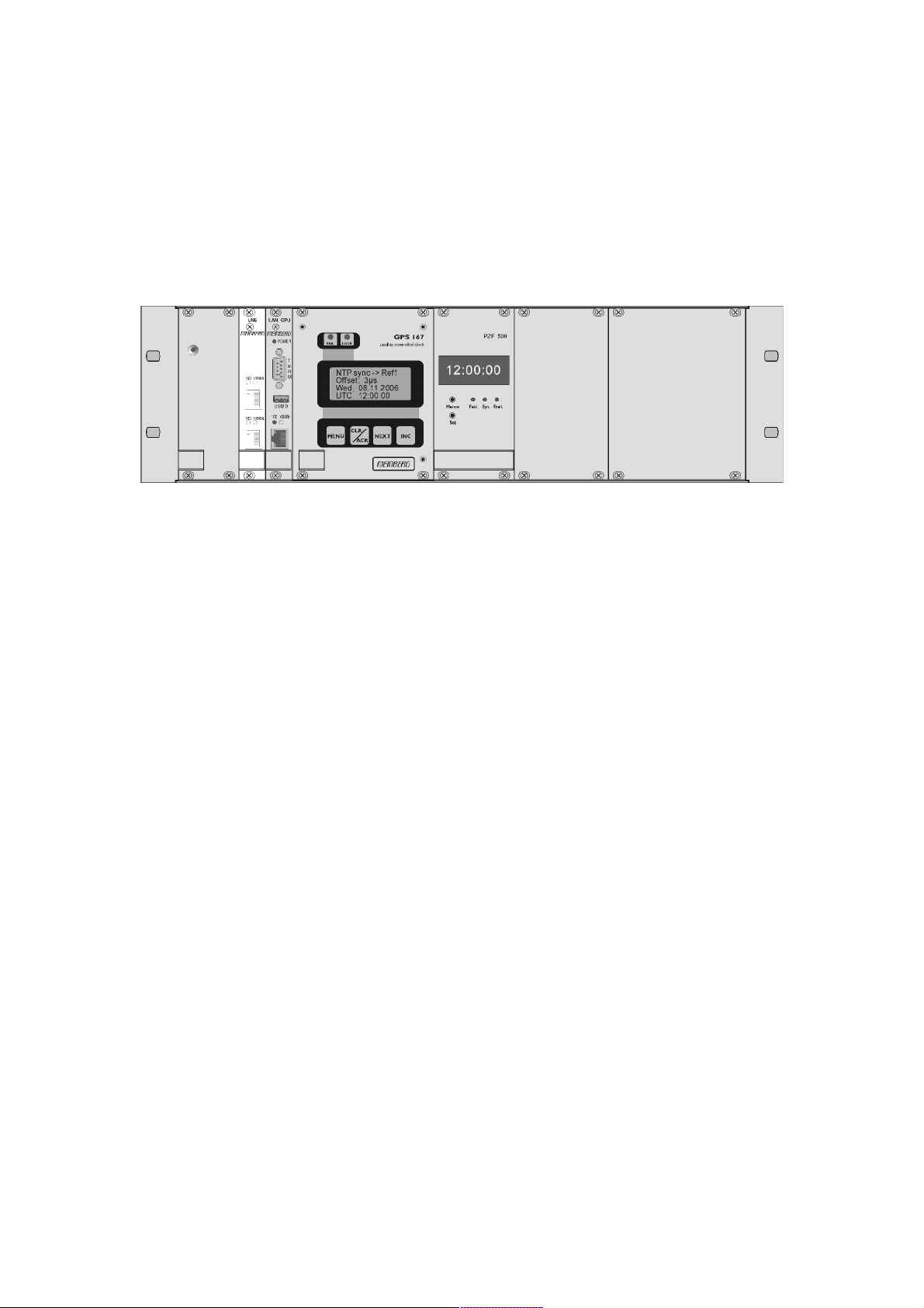
Front View LANTIME/SHS
The implemented NTPD distributes the reference time from the SHS receiver cyclic
in the network. Information on the NTPD is monitored on the LC display or can be
inquired via the network.
The installation of LANTIME is very easy for the system/network administrator. The
network address, the netmask and the default gateway have to be configured from the
front panel of LANTIME. The network address or the equivalent name of LANTIME
has to be shown to all NTP clients in the TCP/IP network.
As well as NTP the Linux system also supports a number of further network
protocols: HTTP(S), FTP, SSH and Telnet. Because of this remote configuration or
status requests can come from any WEB browser. This access via the network can be
deactivated. Changes in the receiver status, errors or other important events are
logged either on the local Linux system or on an external SYSLOG-Server. In
addition messages can be sent to a data center via SNMP traps or automatically
generated e-mails where they can be recorded. Furthermore all alarm messages can be
displayed by the large display VP100/20/NET that is accessed via network
connection. In order to avoid a service interruption several LANTIME NTP servers
can be installed in the same network to obtain redundancy.
12
Page 13

Supported Network Services
The following network services are provided via RJ45 10/100Base-T Ethernet (Auto
sensing):
- NTP v2, v3, v4
- NTP broadcast mode
- NTP multicast
- NTP symmetric keys
- NTP Autokey
- Simple Network Time Protocol (SNTP)
- TIME
- SNMP v1,2,3 with extended SNMP-Agent and SNMP-Traps for NTP and reference clock status
- DHCP Client
- NFS
- TELNET
- FTP
- HTTP
- HTTPS with Openssl2
- SSH2 Secure Shell Login
- Alarm messages via e-mail
- IPv6
- 3 global IPv6 addresses configurable
- Autoconf Feature to be disabled
- supported network services: NTP, HTTP, HTTPS, SNMP, SSH
- Windows „net time“ via NETBIOS
- Winpopup (Window Mail)
13
Page 14

Additional Features and Options
- external NTP timeserver
- free configuration of NTP: thereby MD5 authentication and access control via address & mask restriction
- extended menu guidance for configuration and monitoring via Telnet, SSH or
serial terminal interface
- optional up to 3 RJ45/10/100 Mbit Ethernet interfaces
- extended HTTP statistic support with long-term graphic and access statistic to
NTP
- alarm messages can be displayed on external large display VP100/20/NET
- USB memory stick slot for extended functionality: software update, transfer of
secure certificates, log files and configurations, keypad locking
User Interface
- terminal connection via serial interface, status LED
- Web browser interface with graphical statistic of the one-day cycle offsets
- Telnet or Secure Shell Login for password protected operation of the Linux operating system
- FTP access for updating the operating system and downloading log files
- Simple Network Management Protocol for automatically SNMP-Traps in case of
alarm
- SYSLOG messages can be passed to different computers
- configurable e-mail notification
- Simulation of a synchronous radio clock in order to operate without antenna
Options
- up to two further Ethernet RJ45 connectors
- Frequency and pulse outputs via BNC connectors (e.g. 10 MHz, 2.048 MHz, PPS)
- higher free running accuracy with optional oscillators (OCXO)
- IRIG-B outputs
- ANZ14/NET or VP100/20/NET as display connected via network
14
Page 15

Why to use a Network Timeserver
A network timeserver should be used if accurate time is essential for undisturbed
operation. It is possible to synchronize computers in a network using Public Domain
Time servers over the Internet, but there are good reasons not to use them:
- The possibility to send notification via e-mail or SNMP-Trap to an administrator
in the event of any synchronisation failure.
- The computers in the network do not have a reliable internet connection.
- The computers in the network cannot rely on the availability of external timeservers. Most operators of these timeservers do not guarantee continuous availability nor the accuracy of their service.
- NTP is able to compensate for the propagation delay of the network packets only
in case of “usual” internet traffic. However, if unforeseen occurrences cause
badly fluctuating propagation times, it is possible that the time synchronisation
is disturbed. Reasons for this may be: hacker attacks, numerous upcoming new
viruses etc.
- An own timeserver cannot be easily compromised by external sources.
Network Time Protocol (NTP)
NTP is a common method for synchronization of hardware clocks in local und
global networks. The basic concept, version 1 [Mills88], was published in 1988 as
RFC (Request For Comments). Experiences made from the practical use in Internet
was followed by version 2 [Mills89]. The software package NTP is an
implementation of the actual version 3 [Mills90], based on the specification RFC1305 from1990 (directory doc/NOTES). Permission to use, copy, modify and
distribute this software for any purpose and without fee is hereby granted (read File
COPYRIGHT).
NTP's way of operation is basically different from that of most other protocols. NTP
does not synchronize all connected clocks, it forms a hierarchy of timeservers and
clients. A level in this hierarchy is called a stratum, and Stratum-1 is the highest level.
Timeservers of this level synchronize themselves by a reference time source, such as
a radio controlled clock, GPS-receiver or modem time distribution. Stratum-1-Servers
distribute their time to several clients in the network which are called Stratum-2.
A high precision synchronization is feasible because of the several time references.
Every computer synchronizes itself by up to three valued time sources. NTP enables
the comparison of the hardware times and the adjustment of the own clock. A time
precision of 128 ms, often better than 50 ms, is possible.
15
Page 16

NTP Target
The software package NTP was tested on different UNIX systems. Many UNIX
systems have pre-installed a NTP client. Only some configurations have to be made
(/etc/ntp.conf - see NTP Client Installation). NTP clients as freeware or shareware are
also available for the most other operating systems like Windows
XP/2000/NT/95/98/3x, OS2 or MAC. The following WEB site is recommended to
get the latest version of NTP: "http://www.eecis.udel.edu/~ntp/". More information
you can find on our web page at "http://www.meinberg.de/english/sw/ntp.htm".
NTP-Client Installation
The following example shows the installation of a NTP client under UNIX. First
make sure that there is no NTP installed on your computer because many UNIX
operating systems include NTP already.
The shipped source code of the NTP daemon has to be compiled on the target system.
Using the enclosed script file configures the compilation of the NTP daemon and all
tools.
configure
All necessary information from the system will be collected and the corresponding
make files will be generated in the subdirectories.
After that the NTP daemon and all needed utilities will be generated. Therefore type:
make
While compiling the NTP daemon several warnings may appear. These warnings are
mostly unimportant. In case of problems during the compilation read the system
dependent notes in the subdirectory ‘html’.
Afterwards the generated programs and tools have to be moved in the corresponding
directories. Therefore type:
make install
The time adjustment can occur in different ways. Either the system time can be set
once by using the tool "ntpdate lantime" or the NTPD daemon is started. In the first
case it is recommended to set the time automatically with "cron" or once when
booting the system. The second case is described below.
First a file named /etc/ntp.conf has to be generated with an editor. Adapting the file to
Meinberg LANTIME it should contain the following:
# Example for /etc/ntp.conf for Meinberg LANTIME
server 127.127.1.0 # local clock
server 172.16.3.35 # TCPIP address of LANTIME
# optional: Driftfile
# driftfile /etc/ntp.drift
# optional: activate all messages in syslogfile
# logconfig =all
16
Page 17

The NTP daemon is started with "ntpd" or, using "rc.local", while booting the system.
Status messages during operation are saved in /var/adm/messages and /
var/adm/syslog (corresponding to the syslog configuration).
e.g.: tail /var/log/messages
shows the last lines from the file "messages"
The status messages can also be redirected in a log file by using the following option:
ntpd -llogfile
The command "ntpq" in the directory "ntpq" requests the actual status of the NTP
daemon (see also doc/ntpq.8).
e.g.: ntpq/ntpq
An interpreter appears; Type "?" for a list of all available commands. The command
"peer" is used to list all active reference clocks:
remote refid st t when poll reach delay offset jitter
================================================================================
LOCAL(0) LOCAL(0) 3 l 36 64 3 0.00 0.000 7885
lantime .GPS. 0 l 36 64 1 0.00 60.1 15875
with the following meaning:
- remote: list of all valid time servers (ntp.conf)
- refid: reference number
- st: actual stratum value (hierarchy level)
- when: last request (seconds)
- poll: period of requesting the time server (seconds)
- reach: octal notation of the successful requests, shifted left
- delay: delay of the network transmission (milliseconds)
- offset: difference between system time and reference time
(milliseconds)
- jitter: variance of the offsets (milliseconds)
Repeatedly "peer" commands lets the user observe the accuracy of the NTP daemon.
Every 64 seconds (value of -poll) a new time string is red in from the radio clock. The
NTP daemon needs approx. 3...5 minutes for initialisation. This is indicated by a
wildcard (*) on the left side of the remote name.
The NTP daemon terminates itself if the system time differs from the UTC time by
more than 1024 seconds. This often happens when the time zone is not correctly set
(see also system manual "zic" or "man zic").
17
Page 18

GPS satellite controlled clock
A Meinberg GPS167 satellite controlled radio clock is used as a reference time
base. The satellite receiver clock GPS167 has been designed to provide extremely
precise time to its user. The clock has been developed for applications where
conventional radio controlled clocks can not meet the growing requirements in
precision. High precision available 24 hours a day around the whole world is the main
feature of the new system which receives its information from the satellites of the
Global Positioning System.
The Global Positioning System (GPS) is a satellite-based radio-positioning,
navigation, and time-transfer system. It was installed by the United States Department
of Defence and provides two levels of accuracy: The Standard Positioning Service
(SPS) and the Precise Positioning Service (PPS). While PPS is encrypted and only
available for authorized (military) users, SPS has been made available to the general
public.
GPS is based on accurately measuring the propagation time of signals transmitted
from satellites to the user’s receiver. A nominal constellation of 21 satellites together
with 3 active spares in six orbital planes 20000 km over ground provides a minimum
of four satellites to be in view 24 hours a day at every point of the globe. Four
satellites need to be received simultaneously if both receiver position (x, y, z) and
receiver clock offset from GPS system time must be computed. All the satellites are
monitored by control stations which determine the exact orbit parameters as well as
the clock offset of the satellites' on-board atomic clocks. These parameters are
uploaded to the satellites and become part of a navigation message which is
retransmitted by the satellites in order to pass that information to the user’s receiver.
The high precision orbit parameters of a satellite are called ephemeris parameters
whereas a reduced precision subset of the ephemeris parameters is called a satellite’s
almanac. While ephemeris parameters must be evaluated to compute the receiver’s
position and clock offset, almanac parameters are used to check which satellites are in
view from a given receiver position at a given time. Each satellite transmits its own
set of ephemeris parameters and almanac parameters of all existing satellites.
18
Page 19

GPS167 Features
The hardware of GPS167 is a 100 mm x 160 mm microprocessor board. The front
panel integrates a 2 x 40 character LC display, two LED indicators and 5 push
buttons. The receiver is connected to the antenna/converter unit by a 50 Ω coaxial
cable (refer to "Mounting the Antenna"). Feeding the antenna/converter occurs DC
insulated via the antenna cable. Optionally an antenna splitter for up to four receivers
connected to one antenna is available.
The navigation message coming in from the satellites is decoded by GPS167´s
microprocessor in order to track the GPS system time with an accuracy of better than
500 ns or 250 nsec (OCXO). Compensation of the RF signal’s propagation delay is
done by automatic determination of the receiver’s position on the globe. A correction
value computed from the satellites´ navigation messages increases the accuracy of the
board’s TCXO or OCXO to 10
-9
and automatically compensates the oscillators aging.
The last recent value is restored from the battery buffered memory at power-up.
Time Zone and Daylight Saving
GPS system time differs from the universal time scale (UTC) by the number of leap
seconds which have been inserted into the UTC time scale after GPS had been
initiated in 1980. The current number of leap seconds is part of the navigation
message supplied by the satellites, so GPS167´s internal real time is based on UTC.
Conversion to local time including handling of daylight saving year by year can be
done by the receiver’s microprocessor if the corresponding parameters are set up by
the GPS Monitor (included Windows software).
Internally LANTIME always runs on UTC based time. NTP calculates this UTC time
from the GPS receivers local time. The time zone of LANTIME is fixed to UTC.
However, the time monitored on the LC display is the GPS receiver's local time.
19
Page 20

Mounting the GPS Antenna
Type of cable diameter
Ø [mm]
Attenuation at 100MHz
[dB]/100m
max. lenght
[m]
RG58/CU 5mm 15.9 300
1
RG213 10.5mm 6.9 700
1
1)This specifications are made for antenna/converter units produced after January, 2005
The values are typically ones; the exact ones are to find out from the data sheet of the
used cable.
The GPS satellites are not stationary but circle round the globe in a period of about
12 hours. They can only be received if no building is in the line-of-sight from the
antenna to the satellite, so the antenna/converter unit must be installed in a location
from which as much of the sky as possible can be seen. The best reception is given
when the antenna has a free view of 8° angular elevation above the horizon. If this is
not possible the antenna should be installed with a mostly free view to the equator
because of the satellite courses which are located between latitudes of 55° North and
55° South. If this is not possible problems occur especially when at least four
satellites for positioning have to be found.
The antenna/converter unit can be mounted on a pole with a diameter up to 60 mm or
on a wall. A 50 cm plastic tube, two holders for wall-mounting and clamps for pole-
mounting are added to every GPS167. A standard coaxial cable with 50 Ω impedance
should be used to connect the antenna/converter unit to the receiver. The maximum
length of cable between antenna and receiver depends on the attenuation factor of the
used coaxial cable.
Example:
Up to four GPS167 receivers can be run with one antenna/converter unit by using the
optional antenna splitter. The total length of one antenna line between antenna,
splitter and receiver must not be longer than the max. length shown in the table above.
The position of the splitter in the antenna line does not matter. When installing the
high voltage protector CN-UB/E (CN-UB-280DC) be aware to set it directly after
reaching indoor. The CN-UB/E is not for outdoor usage.
20
Page 21
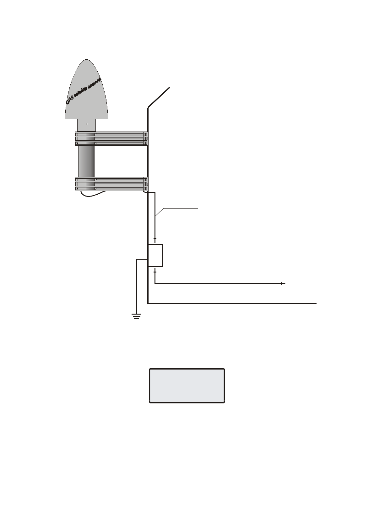
Assembly with CN-UB/E
Type N / BNC
male
Type N
male
Type N
male
CN-UB/E
1.5m max.
Type N
male
GPS167
Antenna
Meinberg
GPS
As short as possibl e!
ANTENNA
SHORT-CIRCUIT
DISCONNECT POWER
!!!
display:
If this message appears the clock has to be disconnected from the mains and the
defect eliminated. After that the clock can be powered-up again. The antenna supply
voltage must be in a range of 18.5 VDC (no load) and 17 V
antenna).
Antenna Short-Circuit
In case of an antenna line short-circuit the following message appears in the
(connected GPS
21
DC
Page 22

General information DCF77 PZF
The German long wave transmitter DCF77 started continuous operation in 1970.
The introduction of time codes in 1973 build the basic for developing modern radio
remote clocks.
The carrier frequency of 77.5 kHz is amplitude modulated with time marks each
second. The BCD-coding of the time telegram is done by shifting the amplitude to
25% for a period of 0.1s for a logical '0' and for 0.2s for a logical '1'. The receiver
reconstructs the time frame by demodulating this DCF-signal. Because the AM-signal
is normally superimposed by interfering signals, filtering of the received signal is
required. The resulting bandwidth-limiting causes a skew of the demodulated time
marks which is in the range of 10 ms. Variations of the trigger level of the
demodulator make the accuracy of the time marks worse by additional +/-3 ms.
Because this precision is not sufficient for lots of applications, the PTB (Physical and
Technical Institute of Germany) began to spread time information by using the
correlation technique.
The DCF-transmitter is modulated with a pseudo-random phase noise in addition to
the AM. The pseudo-random sequence (PZF) contains 512 bits which are transmitted
by phase modulation between the AM-time marks. The bit sequence is build of the
same number of logical '0' and logical '1' to get a symmetrical PZF to keep the
average phase of the carrier constant. The length of one bit is 120 DCF-clocks,
corresponding to 1,55 ms. The carrier of 77.5 kHz is modulated with a phase
deviation of +/-10° per bit. The bit sequence is transmitted each second, it starts
200ms after the beginning of an AM second mark and ends shortly before the next
one.
Compared to an AM DCF77-receiver, the input filter of a correlation receiver can be
dimensioned wide-bandwidth. The incoming signal is correlated with a reconstructed
receiver-PZF. This correlation analysis allows the generation of time marks which
have a skew of only some microseconds. In addition, the interference immunity is
increased by this method because interference signals are suppressed by averaging the
incoming signal. By sending the original or the complemented bit sequence, the
BCD-coded time information is transmitted.
The absolute accuracy of the generated time frame depends on the quality of the
receiver and the distance to the transmitter, but also on the conditions of transmission.
Therefore the absolute precision of the time frame is better in summer and at day than
in winter and at night. The reason for this phenomenon is a difference in the portion
of the sky wave which superimposes the ground wave. To check the accuracy of the
time frame, the comparison of two systems with compensated propagation delay is
meaningful.
22
Page 23

Features of PZF5xx
The PZF5xx is a high precision receive module for the DCF77-signal build in euro
card size (100 mm x 160 mm).
The micro controller of the system correlates its receiver-PZF with the incoming
pseudorandom sequence and decodes the time information of the DCF-telegram
simultaneously. The controller handles input and output functions of the PZF5xx and
synchronizes the internal real-time clock.
By evaluating the pseudorandom phase noise, the PZF5xx is able to generate time
frames with thousand times the accuracy of standard AM-time code receivers. The
precise regulation of the main oscillator (TCXO, OCXO optional for higher accuracy)
of the radio clock is possible therefore. So, the PZF5xx can be used as a standard
frequency generator besides the application as a time code receiver. Six fixed and one
settable TTL-level standard frequencies are available at the rear VG-connector. The
synthesizer frequency exists as an open drain output and a sine wave signal also.
The PZF5xx delivers TTL-low and TTL-high active pulses per minute and per second
further. To distribute information concerning date, time and status, two independent
serial interfaces (RS232) are used which are configurable in a setup menu.
Like mentioned before, the PZF5xx includes a battery-backed real-time clock which
runs crystal-precise if the main power supply fails.
Important system parameters are stored in a battery-backed (RAM of the RTC) or
non-volatile (EEPROM) memory.
If an update of system software becomes necessary, the new firmware can be loaded
via serial interface (COM0) without removing the PZF5xx for inserting a new
EPROM.
Antenna
The PZF5xx operates with a ferrite antenna which is damped to match the
bandwidth needed for the correlation reception.
Assembly of antenna
The antenna has to be mounted as exactly as possible. Turning it out of the main
receive direction will result in less accurate time frames. The antenna must be placed
in longitudinal direction to the DCF-transmitter (Frankfurt). The nearness to
microcomputers should be avoided and the antenna should be installed with a
minimum distance of 30cm to all metal objects, if possible. A distance of several
meters to TV- or computer monitors must be kept.
After switching the PZF5xx to the menu 'PZF STATE', the adjustment of the antenna
can be executed. The displayed value is proportional to the received field strength.
23
Page 24

The best method of mounting the antenna is to look for the minimum field strength
and turn the antenna by 90° to maximum then. A high field strength on its own is no
guarantee for good conditions of reception, because interfering signals within the
bandwidth of the receiver also have an effect on the displayed value.
The maximum interference immunity can be found by looking at the autocorrelation
coefficient (in percent) in the menu 'PZF-STAT'. The displayed value should be close
to 75 % for best reception.
24
Page 25

Powering Up the System
Server not ready
NTP: Not Ready
Tue, 05.06.2001
MESZ 14:23:03
When the LANTIME/SHS is switched on the SHS STATE menu is displayed
because the two receivers (GPS and PZF) are usually not synchronized yet. After the
configured time limit is reached the LANTIME/SHS goes to normal operation. The
following notes should be taken into consideration:
- the GPS antenna/converter unit must be installed in a location from which as
much of the sky as possible can be seen (see "Mounting the GPS antenna")
- the PZF antenna must be positioned to optimise the correlation better than 60 %
- the distance to the German long wave transmitter have to be configured
- the time limit (the max. accepted time difference between GPS and PZF) has to
be set to the needed accuracy (default 10 ms)
Some menues can be called not before the single board computer has booted. Because
of this the state menues for the PZF and the setup for the LAN parameters can not be
edited until the bootphase has finished (approx. 1 minute).
Booting the GPS receiver
If both the antenna and the power supply have been connected the system is ready
to operate. About 10 seconds after power-up the receiver’s oscillator has warmed up
and operates with the required accuracy. If the receiver finds valid almanac and
ephemeris data in its battery buffered memory and the receiver’s position has not
changed significantly since its last operation the receiver can find out which satellites
are in view now. Only a single satellite needs to be received to synchronize and
generate output pulses, so synchronization can be achieved maximally one minute
after power-up.
If the receiver position has changed by some hundred kilometres since last operation,
the satellites´ real elevation and Doppler might not match those values expected by
the receiver thus forcing the receiver to start scanning for satellites. This mode is
called Warm Boot because the receiver can obtain ID numbers of existing satellites
from the valid almanac. When the receiver has found four satellites in view it can
update its new position and switch to Normal Operation. If the almanac has been
lost because the battery had been disconnected the receiver has to scan for a satellite
and read in the current almanacs. This mode is called Cold Boot. It takes 12 minutes
until the new almanac is complete and the system switches to Warm Boot mode
scanning for other satellites.
25
Page 26

Booting the Single Board Computer
NORMAL OPERATION
NTP: Not Ready
Tue, 05.06.2001
MESZ 14:23:03
NORMAL OPERATION
NTP: Not Sync
Tue, 05.06.2001
MESZ 12:00:00
NORMAL OPERATION
NTP: Offs:3ms
Thu, 05.06.2001
MESZ 12:00:00
The LINUX operating system is loaded from a packed file on the flash disk of the
single board computer to a RAM disk. All files of the flash disk are stored in the
RAM disk after booting. Because of that it is guaranteed that the file system is in a
defined condition after restart. This boot process takes approx. one minute. During
this time the following message appears on the display:
Once per second the GPS compares the GPS time with the PZF5xx time. Both the
pulses per second and the serial time strings are compared. If the calculated deviation
exceeds the configured time limit or one of the receiver stops generating time strings
or pulses, the hybridsystem stops sending time information to the NTP server. Once
the hybridsystem sent a time string, the NTP daemon is started with the
corresponding parameters. After that the NTPD starts synchronisation with the
references. The references are usually the RTC of the single board computer, the
serial time string and the pulse per second (PPS) from the hybridsystem. If the NTPD
is started but not synchronous with the hybridsystem yet, the following message is
displayed:
For the synchronisation of the NTPD with the GPS it is necessary that the GPS
receiver is synchronous with the GPS time (LOCK LED is turned on). Also the time
difference between the GPS und PZF receiver must be less then the time limit error.
In this case the following message is monitored on the display:
The second line shows the user that the NTPD is synchronized with the GPS with an
offset of -3 ms. Because of the internal time of the NTP which is adjusted by a
software PLL (phase locked loop) it takes a certain time to optimise this offset. The
NTPD tries to keep the offset below ±128 ms; if the offset becomes too large the
system time is set with the GPS time. Typically values for the offset are +-5 ms after
the NTPD has already synchronized. If NTPD is not synchronised and GPS receiver
is then, the green LOCK-LED is blinking.
26
Page 27

Configuration User Interface
There are several ways to configure the LANTIME parameters:
Command Line Interface (CLI) via TELNET
Command Line Interface via SSH
Command Line Interface via serial interface terminal (BGT versions only)
HTTP Interface
Secure HTTP Interface (HTTPS)
Front panel LCD Interface
SNMP Management
To put LANTIME into operation for the first time an IP address is entered via the
front panel keys and LC display (refer to: DHCP IPv4 or AUTOCONF IPv6).
LANTIME variants without LC display have to be given the IP address via the serial
interface in the front panel, running a terminal software e.g. on a laptop. If once the
IPv4 address, netmask and IPv4 GATEWAY are configured, or the network interface
is initialised by IPv6 SCOPE-LINK, the LANTIME is accessible from any computer
in the network (remote).
To set up a TELNET connection the following commands are entered:
telnet 198.168.10.10 // LANTIME IP address
user: root
password: timeserver
With “setup” the configuration program is started.
To set up a SSH connection the following commands are entered:
ssh root@198.168.10.10 // LANTIME IP address
password: timeserver
With “setup” the configuration program is started.
To set up a HTTP connection the following address is to enter in a web browser:
http://198.168.10.10 // LANTIME IP address
password: timeserver
To set up a Secure HTTP (HTTPS) connection the following address is entered in a
web browser:
https://198.168.10.10 // LANTIME IP address
password: timeserver
27
Page 28

The Front Panel Layout
GPS FAIL LED
The FAIL LED is turned on whenever the TIME_SYN output is low (receiver is
not synchronized).
GPS LOCK LED
The LOCK LED is turned on when after power-up the receiver has acquired at least
four satellites and has computed its position. In normal operation the receiver position
is updated continuously as long as at least four satellites can be received. The LOCK
LED is blinking when the GPS has locked and the NTP is not synchronized. If a time
limit error occurs both LEDs FAIL and LOCK are blinking.
LC Display
The 4 x 16 character LC display is used to show the receiver’s status and let the
user edit parameters. The keys described below let the user select the desired menu.
The next chapter lists all available menus in detail. A quick reference of the available
menus and submenus can be found at the end of this document.
MENU Key
This key lets the user step through several display menus showing specific data.
CLR/ACK Key
This key has to be used when parameters are to be modified. When this key is
pressed the parameters that have been edited are saved in the battery buffered
memory. If the menu is left without pressing CLR/ACK all changes are discarded.
NEXT Key
When editing parameters (LCD cursor is visible) this key moves the cursor to the
next digit with respect to the next parameter to be edited. If the current menu just
displays data (cursor not visible) pressing this key switches to a submenu (if
available).
INC Key
When editing parameters this key increments the digit or letter at the cursor
position.
28
Page 29

Configuration via LC Display
On first installation of LANTIME the network parameters can only be configured
by the front panels push buttons and the LC display. Press MENU until the SETUP
menus appear on the display. The first setup menu are the LAN PARAMETERS.
Pressing NEXT further setup menus appear. Pressing CLR/ACK the LAN
PARAMETERS menu is entered. The submenu TCP/IP ADDRESS appears. Pressing
NEXT the following submenus can be chosen: NET MASK, DEFAULT
GATEWAY, IPv6 address, HOSTNAME, DOMAINNAME, NAMESERVER and
REMOTE CONNECT. CLR/ACK lets the user enter the corresponding submenu to
make changes with NEXT and INC. Pressing CLR/ACK after changing parameters
acknowledges the changes. Leaving the menu with MENU all changes are discarded
and the setup menu is displayed again. All changed settings of the LAN
PARAMETER’s sub menu come into affect not before MENU is pressed once again
and the changes are confirmed.
The unique 32 bit TCP/IP address must be set by the network administrator. The net
mask will be defined by the network. It is probable that you will need to set up the
default gateway also.
The correct connection to the LANTIME can be reviewed from any other workstation
in the network with the program PING.
REMOTE CONNECT lets the user enable or disable all connections via network (e.g.
TELNET, FTP or HTTP). If changes occur via HTTP interface or setup program the
message “REMOTE CONNECT: partial enabled” may appear. The NTP protocol will
restart after any change.
NOTE: Any HTTP, HTTPS, SSH or TELNET connection to the LANTIME is
possible only if REMOTE CONNECT is enabled!
29
Page 30

The menus in Detail
NORMAL OPERATION
NTP: Offs:3ms
Thu, 05.06.2001
MESZ 12:00:00
LANTIME:2.00
S/N:10000110
GPS167 :2.06
S/N:10000110
RECEIVER INFO
PROUT: 0 NCOM:2
SYNTH: n/a
TCXO_LQ gps167_3
1024 8c:2c:72:5e
:9b:5b:10:83:c9:
c8:eb:7d:49 tim
eserver
NTP:4.0.99f
OS:2.2.14.01
MAC:000000000000
Meinberg
Root Menu
The root menu is shown when the receiver has completed initialisation after powerup. The left side of the first line of the display shows the receiver’s mode of operation
as described above. The text "NORMAL OPERATION" might be replaced by
"COLD BOOT", "WARM BOOT" or "UPDATE ALMANAC". If the antenna is
disconnected or not working properly, the text "ANTENNA FAULTY" is displayed
instead.
On the right side of the display the current date, the name of the time zone (as defined
in the setup menu) and local time are monitored. If the "IGNORE LOCK" option is
enabled an "*" will be shown behind the time.
If the NEXT key is pressed from the root menu a submenu is displayed showing the
receiver’s software revision of the LANTIME software and the GPS167 flash
software:
If the NEXT key is pressed twice from the root menu a submenu is displayed showing
the NTP software version, the operating system version and the MAC address of the
integrated net card.
Pressing NEXT the third time the fingerprint of the SSH key is displayed:
Pressing NEXT the fourth time the receiver info is displayed:
30
Page 31

Menu SHS State
SHS STATE
DIFF: <1ms
GPS: sync
PZF: sync
RECEIVER POS.
Lat: 51°59’00”N
Lon: 9°13’35”E
ALT: 187 m
RECEIVER POS.
Lat: 51.9835°
Lon: 9.2236°
ALT: 187 m
RECEIVER POS.
x: 3885597m
y: 631166m
z: 5001820m
The SHS state is displayed automatically whenever a time limit error occurs, i.e.
the deviation between GPS time and PZF time is larger than the configured limit.
After powering-up the LANTIME this menu is displayed as long as the time deviation
is larger than the time limit. After the deviation becomes smaller than the time limit,
the main menu is displayed automatically. However, if a time limit error occurs
during the normal operation (not after powering-up) the error must be acknowledged
to change back to the normal operation by pressing the CLR/ACK key in the SHS
state menu. It is also possible to acknowledge the error by a modification via the
HTTP interface. An acknowledgement is essential even if the time limit error has
settled itself! Generating time strings again starts not before the acknowledgement
took place.
Note: As long as both of the two LEDs FAIL and LOCK blink simultaneously, a
time limit error took place and no time string is sent to the NTP.
Menu RECEIVER POS.
This menu shows the current receiver position. The NEXT key lets the user select
one of three formats. The default format is geographic latitude, longitude and altitude
with latitude and longitude displayed in degrees, minutes and seconds. The next
format is geographic too, with latitude and longitude displayed in degrees with
fractions of degrees. The third format displays the receiver position in earth centred,
earth fixed coordinates (ECEF coordinates). The three formats are shown below:
31
Page 32

Menu SV CONSTELLATION
SV CONSTELLATION
SVs in view: 8
Good Svs: 8
Sel: 2 8 26 19
DILUTION OF PREC
PDOP: 2.32
TDOP: 1.12
GDOP: 2.58
SV 2 INFO:
El:36° Az: 159°
Dist: 22602 km
Dopp: +2.555 kHz
The SV constellation menu gives an overview of the current satellites (SVs) in
view. The second line of the display shows the number of satellites with an elevation
of 5° or more (In view), the number of satellites that can be used for navigation
(Good) and the selected set of satellites which are used to update the receiver position
(Sel).
The precision of the computed receiver position and time is affected by the geometric
constellation of the four satellites being used. A set of values called dilutions of
precision (DOP) can be computed from the geometric constellation. Those values can
be displayed in a submenu of the SV constellation menu. PDOP is the position
dilution of precision, TDOP is the time dilution of precision, and GDOP, computed
from the others above, is the general dilution of precision. Lower DOP values mean
more precision.
Menu SV POSITION
This menu gives information on the currently selected satellite (SV). The satellite’s
ID number, its elevation, azimuth and distance from the receiver position reflect the
satellite’s position in the sky whereas the Doppler shows whether the satellite is
coming up from the horizon (Doppler positive) or going down to the horizon
(Doppler negative). All satellites in view can be monitored by using the NEXT key.
32
Page 33

Menu SETUP
SETUP
LAN PARAMETERS
SAVE SETTINGS ?
INC -> YES
MENU -> NO
From this menu, several topics can be selected which let the user edit parameters or
force special modes of operation. A specific topic can be selected using the NEXT
key. Depending on the current topic, pressing the CLR/ACK key either enters edit
mode with the selected set of parameters or switches to the selected mode of
operation (after the user has acknowledged his decision). Once edit mode has been
entered, the NEXT key lets the cursor move to the digit or letter to be edited whereas
the INC key increments the digit or letter under the cursor. If changes have been
made, the CLR/ACK key must be pressed. If all changes have been made in one setup
submenu you have to press the MENU key. After that you will be asked to save the
settings. Press INC to change and save the last changes. Otherwise all changes are
discarded when the user presses the MENU key in order to return to the SETUP
display.
33
Page 34

SETUP SHS Time Limit
SETUP
SHS max.Diff
act.Diff: < 1ms
max.Diff: 001ms
SETUP
LAN PARAMETERS
TCP/IP ADDRESS
000.000.000.000
SETUP
LAN PARAMETERS
NET MASK
255.255.255.000
SETUP
LAN PARAMETERS
Reset factory
settings
Reset Factory ?
INC -> YES
MENU -> NO
In this menu the maximum time limit is to be configured. If the deviation between
GPS time and PZF time exceeds the configured time limit, the hybridsystem stops
generating time strings. The time limit can be set between 1 ms and 400 ms.
SETUP LAN PARAMETERS
In this submenu the network parameters are configured. These parameters have to
be adapted to the existing network when the LANTIME is installed the first time. The
following parameters can be set: TCP/IP ADDRESS, NETMASK, DEFAULT
GATEWAY, IPv6 ADDRESS HOSTNAME, DOMAINNAME, NAMESERVER,
SYSLOG SERVER, SNMP MANAGER, REMOTE CONNECT, RESET
FACTORY SETTINGS und NET LINK MODE. All settings are applied to the
first Ethernet interface only. All further Ethernet interfaces have to be configured via
HTTP or CLI interface. With the submenu REMOTE CONNECT you can enable or
disable all network connections via TELNET, FTP or HTTP. When the network
parameters have been changed the configuration file is updated and the NTPD is
restarted.
With the submenu RESET FACTORY SETTINGS the following parameters will
be set to the default values:
All configuration parameters of the timeserver are saved on the Flash Disk in the file /
mnt/flash/global_configuration. It is recommended not to modify this file manually
but to use the configuration interface (HTTP, CLI or SNMP). If this file does not
exist, an empty file is generated. The default configuration file is part of the
attachment.
The parameters for speed and mode of the net card can be changed with the menu
item NET LINK MODE. There are 5 modes available: Autosensing, 10 MBit/HalfDuplex, 100 MBit/Half-Duplex, 10 MBit/Full-Duplex, 100 MBit/Full-Duplex.
Default setting is Autosensing.
34
Page 35

SETUP PZF PARAMETERS
SETUP
PZF PARAMETERS
DISTANCE OF
TRANSMITTER
SETUP
PZF PARAMETERS
OSCILLATOR
ADJUSTMENT
SETUP
PZF PARAMETERS
CLEAR FINE
DAC
In this submenu the PZF specific parameters can be edited. The distance to the
transmitter is entered in the menu "DISTANCE OF TRANSMITTER" for
compensating the propagation delay of the received pseudo-random code. This setting
should be done as exact as possible because the absolute precision of the time frame
is influenced by this value.
The basic model of the PZF509 includes a voltage controlled temperature
compensated oszillator (VCTCXO). Its nominal frequency of 10MHz is adjusted by
using two digital-to-analog converters (DACs). One of them is responsible for the
coarse tuning and the other one for the fine adjustment of the oscillator.
The value for the coarse-DAC is settable in the menu "OSCILL. AJUST" in the range
of 0 to 4095. If the edited value exceeds 4095 the maximum value is stored. This
menu only lets the user modify the coarse-DAC (CAL). The fine-DAC (FINE) is
displayed but not to edit. It can be cleared in the next menu.
This value should only be changed by specialized personnel of company
Meinberg and not by the user!
Using the menu "CLR FINE DAC" the DAC is set to its mid-scale value and the
difference to its last value is added to the coarse DAC proportional.
This process is released automatically if the value of the fine DAC exceeds its
limits (0...4095). Therefore the setting of the value to mid-scale by hand is
reserved for service purposes only!
The menu "TIME" lets the user edit the time of the PZF509 in hours, minutes,
seconds and set the daylight saving (MESZ) active or not. The LANTIME itself
always runs on UTC based time. This UTC-time is displayed on the LCD.
35
Page 36

SETUP
PZF PARAMETERS
TIME
The menu "TIME" lets the user edit the date and the day of week of the PZF509 radio
SETUP
PZF PARAMETERS
DATE
clock.
36
Page 37

SETUP TIME ZONE
SETUP
TIME ZONE
TIME ZONE
Off«DAYL SAV-»ON
|MEZ | |MESZ |
+01:00h +02:00h
SETUP
DAYLIGHT SAV ON
DAYLIGHT SAV ON
Date: 26.03.2000
Day of week ***
Time: 2:00:00
DAYLIGHT SAV ON
Date: 25.03.****
Day of week Sun
Time: 2:00:00
SETUP
DAYLIGHT SAV OFF
DAYLIGHT SAV OFF
Date: 29.10.2000
Day of week ***
Time: 3:00:00
DAYLIGHT SAV OFF
Date: 25.10.****
Day of week Sun
Time: 3:00:00
This menu lets the user enter the names of the local time zone with daylight saving
disabled and enabled, together with the zones´ time offsets from UTC. The left part of
the display shows the zone and offset if daylight saving is off whereas the right part
shows name and offset if daylight saving is on. These parameters are used to convert
UTC to local time, e.g. MEZ = UTC + 1h and MESZ = UTC + 2h for central Europe.
The range of date daylight saving comes in effect can be entered using the next two
topics of the setup menu.
SETUP DAYLIGHT SAV ON/OFF
These two topics let the user enter the range of date for daylight saving to be in
effect. Concerning parameter input both topics are handled identically, so they are
described together in this chapter. Beginning and ending of daylight saving may
either be defined by exact dates for a single year or using an algorithm which allows
the receiver to re-compute the effective dates year by year. The figures below show
how to enter parameters in both cases. If the number of the year is displayed as
wildcards (´*´), a day-of-week must be specified. Then, starting from the configured
date, daylight saving changes the first day which matches the configured day-ofweek. In the figure below March 25, 1996 is a Saturday, so the next Sunday is March
31, 1996.
All changeover rules for the daylight saving like "the first/the second/the second to
last/the last Sunday/Monday etc. in the x-th month," can be described by the used
format "first specified day-of-week after a defined date".
If the number of the year is not displayed as wildcards the complete date exactly
determines the day daylight saving has to change (March 31, 1996 in the figures
below), so the day-of-week does not need to be specified and therefore is displayed as
wildcards.
If no changeover in daylight saving is wanted, identical dates and times must be
entered in both of the submenus. In addition identical offsets for DAYLIGHT SAV
37
Page 38

ON/OFF should be configured in the submenu TIMEZONE. After this a restart
SETUP
DAYLIGHT SAV ON
DAYLIGHT SAV ON
Date: 26.03.2000
Day of week ***
Time: 2:00:00
SETUP
DAYLIGHT SAV OFF
DAYLIGHT SAV OFF
Date: 26.03.2000
Day of week ***
Time: 2:00:00
SETUP
TIME ZONE
TIME ZONE
Off«DAYL SAV-»ON
|TIME | | |
+08:00h +08:00h
TIME
should be done.
38
Page 39

SETUP SERIAL PORT
SETUP
SERIAL PORT
SERIAL PORT
PARM: 9600 8N1
MODE: Per second
SETUP
SER. STRING TYPE
SER. STRING TYPE
COM: Meinbg Std
This menu lets the user configure the baud rate and the framing of the serial RS232
port to one of the following values:
Baud Rate: 300 to 19200
Framing: 7E2, 8N1, 8E1, 8O1
COM provides a time string once per second or once per minute.
Default: COM: 19200 baud, 8N1, once per second
The following modes are possible:
Per Second: Time string will be send to next change of second
Per Minute: Time string will be send to next change of minute
On Request: Time string will be send if an '?' will be send to this port
SETUP SERIAL STRING TYPE
This topic is used to select one of several different types of serial time strings or the
capture string for each serial port.
The following time strings can be selected:
- Meinberg Standard String
- GPS167 Capture String
- SAT String
- UNI-Erlangen String
- NMEA String (RMC)
- SPA String
- Computime String
Refer to chapter Time Strings for details.
39
Page 40

SETUP INITIAL POSITION
SETUP
INITIAL POSITION
INITIAL POSITION
Lat: 51°59’00”N
Lon: 9°13’34”E
Alt: 187 m
SETUP
SET INITIAL TIME
SET INITIAL TIME
MESZ
Date: 05.06.2001
Time: 12:00:00
SETUP
IGNORE LOCK
SETUP
IGNORE LOCK
disabled
When the receiver is primarily installed at a new location far away from the last
position saved in the receiver’s memory the satellites in view and their Doppler will
differ so much from those expected due to the wrong position that GPS167 has to
scan for satellites in Warm Boot mode. Making the new approximately known
position available to the receiver can avoid Warm Boot and speed up installation.
SETUP INITIAL TIME
If the receiver’s on-board real time clock keeps a wrong time the receiver is unable
to compute the satellites´ correct elevation angles and Doppler. This submenu enables
the user to change the receiver’s system time for initialisation. After the receiver has
locked, its real time clock will be adjusted using the information from the satellites.
When the antenna is disconnected it is possible to set the LANTIME with any time.
Note that the NTP will not synchronize to a GPS losing its reception or if the
deviation to the system time is larger than 1024 seconds. In this case the menu
IGNORE LOCK has to be active. After setting the clock manually the system should
be restarted (REBOOT).
IGNORE LOCK
Enabling this menu lets the user run the LANTIME without antenna. Normally the
NTPD loses synchronisation with the GPS when the antenna is disconnected or the
GPS did not receive enough satellites (red FAIL LED is turned on). When IGNORE
LOCK is enabled the status information from the GPS is fixed to SYNC. So it is
possible to set the NTPD with any other time entered by the SETUP INITIAL TIME
menu. Usually this menu should be disabled. If this option is enabled an "*" will be
shown behind the time string in the root menu.
40
Page 41

INITIATE COLD BOOT
SETUP
INIT COLD BOOT
Are you sure ?
Press …
INC -> YES
MENU -> NO
SETUP
INIT WARM BOOT
Are you sure ?
Press …
INC -> YES
MENU -> NO
SETUP
ANTENNA CABLE
ANTENNA CABLE
LENGTH: 020m
This menu lets the user initialise all GPS data’s, i.e. all saved satellite data’s will be
cleared. The user has to acknowledge this menu again before the initialisation starts.
The system starts operating in the COLD BOOT mode and seeks for a satellite to read
its actual parameters.
INITIATE WARM BOOT
This menu lets the user force the receiver into the Boot Mode. This may be
necessary when the satellite data in the memory are too old or the receiver position
has changed by some hundred kilometres since last operation. Synchronisation time
may be reduced significantly. If there is valid satellite data in the memory the system
starts in the WARM BOOT mode, otherwise the system changes into COLD BOOT
to read new data’s.
ANTENNA CABLE
This menu asks the user to enter the length of the antenna cable. The received time
frame is delayed by approx. 5 ns per meter antenna cable. The receiver is able to
compensate this delay if the exact cable length is given. The default value is 20 m.
The maximum value that can be entered is 500 m (only with low loss cable).
Resetting Factory Defaults of the GPS
If both, the NEXT key and the INC key on the front panel, are pressed while the
system is powered up the battery buffered memory is cleared and user definable
parameters are reset to factory defaults. The key should be held until the root menu is
displayed on LCD. Due to the fact that the satellites parameters have been cleared, the
system comes up in COLD BOOT mode. The network and NTP parameters will not
be changed.
41
Page 42

Front panel PZF509
Pilot lamps
The 'Feld'-LED is switched on if a DCF-signal with at least minimum field strength
needed for the correlation receiption is detected at the input of the receiver.
The 'Syn.'-LED indicates that the autocorrelation coefficient decreases beyond 52%
and correct receiption is not possible therefore. This happens if a strong interferer
within the bandwidth of the receiver is present or the transmitter is switched of.
If the 'Freil.'-LED is on, it was not possible to synchronize the internal realtime clock
to DCF-time. This condition occures for at most two minutes after switching on the
PZF509, because two DCF-telegrams are checked for plausibility before the data is
taken over. Short disturbance of receiption can cause this state too.
Display
The eight digit alphanumeric display shows important information concerning
status and time. The setting of system parameters is also done with the help of the
display.
Control keys
It is possible to change the displayed information (time, date or status information)
by two keys. The 'Menu'-key selects one of several menus. After presing the
'Set'-button the belonging information appears on the display. Furthermore, the keys
are used to set user-specific parameters in several submenus.
42
Page 43

PZF Menu items
The type of DCF-clock and the software revision are displayed first after power-up.
The following information are readable before the PZF509 switches to time-display
automatically:
PZF REC.
REV:x.xx
The handling of any queries will be simplified if the software revision is given by the
user.
The following menus are available then:
TIME: The current time is displayed.
DATE: The actual date appears on the display.
DAY o.W.: The day of week will be displayed.
PZF STAT: Information about the decoding of the pseudo-random sequence are
available in this menu. The following texts may be displayed:
GSYNC: The pseudo-random sequence is read into the internal RAM for one
second and the system tries to achieve a coarse synchronisation.
This procedure starts after power-up or worse reception for more
than ten seconds.
K: xx%: If the coarse synchronisation was successful, the receiver enters the
state of fine-correlation. The system tries to lock the received PZF
as exact as possible to generate a precise time frame. The display
shows the correlation coefficient at the end of each second, which
can be in the range of 52 % to 77 %. A high value for the coefficient
should be achieved by choosing a suitable position for the antenna.
The essential part of the tracking is completed five seconds after the appearance of
'K:xx%' and the generation of pulses per minute and per second starts. Tracking steps
of three microseconds are possible each second until the internal real time clock is
synchronized (two minutes max.). Afterwards, corrections of the time frame are
executed per minute only. The direction of these steps is displayed by the characters
'>' or '<' behind the digits of the correlation coefficient.
FIELD: The digitised value of the field strength is displayed in this menu.
There is a logarithmic relation between this value and the field
strength. This menu is useful for mounting the antenna, like
described in chapter 'Assembly of antenna.
43
Page 44

The LANTIME configuration interfaces
The LANTIME offers three different options for configuration and status
management: Web interface, Command Line Interface Setup and SNMP. In order to
use the SNMP features of your LANTIME, you need special software like
management systems or SNMP clients. In order to use the web interface, all you need
is a web browser (LANTIME supports a broad range of browsers).
In addition to the SNMP and web interface, you can also manage your LANTIME
configuration via a command line interface (CLI), which can be used via a TELNET
or SSH connection. A setup tool can be started after login, just type “setup” and press
ENTER at the prompt.
There are only a few differences between the web interface and the CLI, most options
are accessible from both interfaces (the CLI has no statistical functions).
The above screenshots show the web interface and the Command Line Interface setup
tool. The CLI setup tool cannot be used by more than one user at a time, the web
interface can be used by more than one user in parallel, but the two or more running
sessions may influence each other. We explicitly do not recommend the parallel usage
of the configuration interfaces.
44
Page 45

The web interface
Connect to the web interface by entering the following address into the address
field of your web browser:
http://198.168.10.10
(You need to replace 198.168.10.10 with the IP address of your LANTIME). If you
want to use an encrypted connection, replace the http:// with https:// in the above
address. You may be prompted to accept the SSL certificate of your LANTIME the
first time you are connecting to the system via HTTPS.
In both HTTP and HTTPS mode, you will see the following login screen:
On this start page you see a short status display, which corresponds with the LC
display on the front panel of the LANTIME unit. The upper line shows the operation
mode of the GPS receiver. As well as “SHS: NORMAL OPERATION” you may also
read “SHS: COLD BOOT”, “SHS: WARM BOOT” or “SHS: UPDATE
ALMANACH”. If the connection to the antenna is broken, a “SHS: ANTENNA
FAULTY” will appear.
In the upper right corner of the LC display the time and time zone can be found,
below that you will find the date and weekday.
On the second line the systems reports the NTP status. During the initial
synchronisation process a “NTP: not sync” indicates that the NTP system is not
synchronised, this can also appear if the GPS looses synchronisation and the NTP
switches back to its “LOCAL CLOCK” time source .
The GPS clock is connected to the LANTIME system internally by using a serial
connection and additionally by using the second pulse. There are therefore 2 reference
clocks used by NTPD, the GPS and PPS time source. You will find the two time
sources in the status information of the NTPD. After the NTP is synchronised, the
Display shows “NTP: Offset GPS: x” or “NTP: Offset PPS: x” where “x” is the actual
offset to the GPS or PPS time source.
This page will be reloaded every 30 seconds in order to reflect the current status of
the unit. Please bear this in mind when you try to login and enter your password. If
you do not press ENTER or the Login button within 30 seconds, the user and the
password field is cleared and you have to start over again.
45
Page 46

Configuration: Main Menu
After entering the right password, the main menu page shows up. This page
contains an overview of the most important configuration and status parameters for
the system.
The start page gives a short overview of the most important configuration parameters
and the runtime statistics of the unit. In the upper left corner you can read which
LANTIME model and which version of the LANTIME software you are using. This
LANTIME software version is a head version number describing the base system and
important subsystems. Below the version you will find the actual hostname and
domain of your LANTIME unit, the IPv4 and IPv6 network address of the first
network interface and on the right side the serial number, the uptime of the system
(time since last boot) and the notification status.
In the second section the actual status of the GPS reference clock and the NTP
subsystem is shown, additional information about the GPS receiver are also found
here. This includes the number of satellites in view and the number of good satellites
in view.
The third section shows the last messages of the system, with a timestamp added. The
newest messages are on top of the list. This is the content of the file /
var/log/messages, which is created after every start of the system (and is lost after a
power off or reboot).
By using the buttons in the lower part of the screen, you can reach a number of
configuration pages, which are described below.
46
Page 47

Configuration: Ethernet
47
Page 48

In the network configuration all parameters related to the network interfaces can be
changed. In the first section you can change the hostname and domain name. You can
also specify two nameserver and two SYSLOG server. In the nameserver and syslog
server fields you may enter an IPv4 or IPv6 address (the syslog servers can be
specified as a hostname, too).
All information written to the LANTIME SYSLOG (/var/log/messages) can be
forwarded to one or two remote SYSLOG servers. The SYSLOG daemon of this
remote SYSLOG needs to be configured to allow remote systems to create entries. A
Linux SYSLOD can be told to do so by using the command “syslogd –r” when
starting the daemon.
If you enter nothing in the SYSLOG server fields or specify 0.0.0.0 as the SYSLOG
servers addresses, the remote SYSLOG service is not used on your LANTIME.
Please be aware of the fact that all SYSLOG entries of the timeserver are stored in /
var/log/messages and will be deleted when you power off or reboot the timeserver. A
daily CRON job is checking for the size of the LANTIME SYSLOG and deletes it
automatically, if the log size is exceeding a certain limit.
By specifying one or two remote SYSLOG servers, you can preserve the SYSLOG
information even when you need to reboot or switch off the LANTIME.
In the second section the possible network protocols and access methods can be
configured. You can enable/disable TELNET, FTP, SSH, HTTP, HTTPS, SNMP and
NETBIOS by checking/unchecking the appropriate check boxes. After you saved
your settings with the “Save” button, all these subsystems are stopped and eventually
restarted (only if they are enabled, of course).
The third section allows you to select the IP protocol version 6. In this version the
IPv4 protocol is mandatory and cannot be disabled, but as a workaround a standalone
IPv6 mode can be achieved by entering an IPv4 address “0.0.0.0” and disabling the
DHCP client option for every network interface of your LANTIME. By doing so, you
ensure that the timeserver cannot be reached with IPv4. Please note that TELNET,
FTP and NETBIOS cannot be used over IPv6 in this version. It is no problem to use
IPv4 and IPv6 in a mixed mode environment on your LANTIME.
48
Page 49

Network interface specific configuration
The interface specific parameters can be found in the Interface section. If your
LANTIME is equipped with only one network interface, you will find only one sub
section (Interface 0). Otherwise you see a sub section for each installed Ethernet port.
Here, the parameters for the network port can be changed. In the upper section of the
page you can enter the IPv4 parameters, the lower part gives you access to the IPv6
parameters of the interface.
IPv4 addresses and DHCP
IPv4 addresses are built of 32 bits, which are grouped in four octets, each
containing 8 bits. You can specify an IP address in this mask by entering four decimal
numbers, separated by a point “.”.
Example: 192.168.10.2
Additionally you can specify the IPv4 netmask and your default gateway address.
Please contact your network administrator, who can provide you with the settings
suitable for your specific network.
If there is a DHCP (Dynamic Host Configuration Protocol) server available in your
network, the LANTIME system can obtain its IPv4 settings automatically from this
server. If you want to use this feature (again, you should ask your network
administrator whether this is applicable in your network), you can change the DHCP
Client parameter to “ENABLED”. In order to activate the DHCP client functionality,
you can also enter the IP address “000.000.000.000” in the LCD menu by using the
front panel buttons of the LANTIME. Using DHCP is the default factory setting.
The MAC address of your timeserver can be read in the LCD menu by pressing the
NEXT button on the front panel twice. This value is often needed by the network
administrator when setting up the DHCP parameters for your LANTIME at the
DHCP server.
If the DHCP client has been activated, the automatically obtained parameters are
shown in the appropriate fields (IPv4 address, netmask, gateway).
IPv6 addresses and autoconf
You can specify up to three IPv6 addresses for your LANTIME timeserver.
Additionally you can switch off the IPv6 autoconf feature. IPv6 addresses are 128 bits
in length and written as a chain of 16bit numbers in hexadecimal notation, separated
with colons. A sequence of zeros can be substituted with “::” once.
49
Page 50

Examples:
"::" is the address, which simply consists of zeros
"::1" is the address, which only consists of zeros and a 1 as the
last bit. This is the so-called host local address of IPv6 and is
the equivalent to 127.0.0.1 in the IPv4 world
"fe80::0211:22FF:FE33:4455"
is a typical so-called link local address, because it uses
the “fe80” prefix.
In URLs the colon interferes with the port section, therefore IPv6IP-addresses are written in brackets in an URL.
("http://[1080::8:800:200C:417A]:80/" ; the last “:80” simply sets
the port to 80, the default http port)
If you enabled the IPv6 protocol, the LANTIME always gets a link local address in
the format “fe80:: ….”, which is based upon the MAC address of the interface. If a
IPv6 router advertiser is available in your network and if you enabled the IPv6
autoconf feature, your LANTIME will be set up with up to three link global addresses
automatically.
The last parameter in this sub section is “Netlink mode”. This controls the port speed
and duplex mode of the selected Ethernet port. Under normal circumstances, you
should leave the default setting (“autosensing”) untouched, until your network
administrator tells you to change it.
High Availability Bonding
The standard moniker for this technology is IEEE 802.3ad, although it is known by
the common names of trunking, port trunking, teaming and link aggregation. The
conventional use of bonding under Linux is an implementation of this link
aggregation.
A separate use of the same driver allows the kernel to present a single logical
interface for two physical links to two separate switches. Only one link is used at any
given time. By using media independent interface signal failure to detect when a
switch or link becomes unusable, the kernel can, transparently to user space and
application layer services, fail to the backup physical connection. Though not
common, the failure of switches, network interfaces, and cables can cause outages. As
a component of high availability planning, these bonding techniques can help reduce
the number of single points of failure.
At this menu point it is possible to add each Ethernet port to a bonding group. At least
two physical Ethernet ports must be linked to one bonding group to activate this
feature. The first Ethernet Port in one bonding group provides the IP-Address and the
net mask of this new virtual device.
50
Page 51

Additional Network Configuration
You can configure additional network parameter like special network routes or
alias definitions. For this you will edit a script file which will be activated every time
after the network configuration will run.
Also the Samba Configuration from „/etc/samba/smb.conf“ can be edited:
51
Page 52

Configuration: Notification
52
Page 53

Alarm events
On this page you can set up different notification types for a number of events. This
is an important feature because of the nature of a timeserver: running unobserved in
the background. If an error or problem occurs, the timeserver is able to notify an
administrator by using a number of different notification types.
The LANTIME timeserver offers four different ways of informing the administrator
or a responsible person about nine different events: EMAIL sends an e-mail message
to a specified e-mail account, SNMP-TRAP sends a SNMP trap to one or two SNMP
trap receivers, WINDOWS POPUP MESSAGE sends a winpopup message to one or
two different computers and DISPLAY shows the alarm message on a wall mount
display model VP100/NET, which is an optional accessory you can obtain for your
LANTIME.
Here is a table of supported events:
"NTP not sync" NTP is not synchronised to a reference time source
"NTP stopped" NTP has been stopped (mostly when very large time offsets
occur)
"Server boot" System has been restarted
"Receiver not responding" No contact to the internal GPS receiver
"Receiver not sync" Internal GPS clock is not synchronised to GPS time
"Antenna faulty" GPS antenna disconnected
"Antenna reconnect" GPS antenna reconnected
"Config changed" Configuration was changed by a user
„Leap second announced“ A leap second has been announced
“TIME LIMIT ERROR” SHS detected time difference
Every event can use a combination of those four notification types, of course you can
disable notification for an event (by just disabling all notification types for this event).
The configuration of the four notification types can be changed in the upper section of
the page, you can control which notification is used for which event in the lower part
of the page.
E-mail messages
You can specify the e-mail address which is used as the senders address of the
notification e-mail (From: address), the e-mail address of the receiver (To: address)
and a SMTP smarthost, that is a mail server forwarding your mail to the receiver’s
mail server. If your LANTIME system is connected to the internet, it can deliver
those e-mails itself by directly connecting to the receivers mail server.
These settings cannot be altered with the LC display buttons of the front panel. Please
note the following:
- The LANTIME hostname and domain name should be known to the SMTP
smarthost
- A valid nameserver entry is needed
- The domain part of the “From:” address has to be valid
53
Page 54

Windows Popup Messages
Most Microsoft Windows operating systems provide you with a local notification
tool. You can send messages via the special Windows protocol in your local network.
It is not necessary to enable the NETBIOS protocol of the LANTIME in order to use
this notification. On the Windows client side it is necessary to activate the “Microsoft
Client for Windows” in the network configuration.
You can enter the Windows computer name of up to two Windows PCs in the
appropriate fields. Every message contains a time stamp and a plain text message:
SNMP-TRAP messages
Up to two SNMP trap receiver hosts can be configured in this subsection, you may
use IPv4 or IPv6 addresses or specify a hostname. Additionally you have to enter a
valid SNMP community string for your trap receiving community. These can be
unrelated to the SNMP community strings used for status monitoring and
configuration access (see SNMP configuration on the “Security” page).
VP100/NET wall mount display
The VP100/NET wall display is an optional accessory for the LANTIME
timeserver, it has an own integrated Ethernet port (10/100 Mbit) and a SNTP client.
The time for the display can be received from any NTP server using the SNTP
protocol (like your LANTIME), additionally the display is capable of showing text
messages, which are sent by using a special utility. The LANTIME can send an alarm
message to one or two VP100/NET displays over the network, whenever an event
occurs for which you selected the display notification type. If this happens, a scrolling
alarm message is shown three times on the display.
Just enter the display’s IP address and its serial number (this is used for
authorisation), which can be found by pressing the SET button on the back of the
display four times. The serial number consists of 8 characters, representing four bytes
in hexadecimal notation.
If you want to use the display for other purposes, you can send text messages to it by
using our command line tool send2display, which can be found on the LANTIME.
This allows you to use the display by CRON jobs or your own shell scripts etc. If you
run the tool without parameters, a short usage screen is shown, explaining all
parameters it may understand. See appendix for a printout of this usage screen.
54
Page 55

User defined Alarm scripts
You can define your own alarm script for every event by using the “Edit user
defined notification script”. This script will be called automatically if one of the
selected events occurs. This user alarm script will be stored on the Flash-Disk at
“/mnt/flash/user_defined_notification”. This script will be called with index and the
alarm message as text. The index value of the test message is 0.
Alarm messages
You can change the alarm message text for every event by using the „Edit
Messages“ button, the messages are stored in a file /mnt/flash/notification_messages
on the flash disk of your timeserver.
55
Page 56

Configuration: Security
56
Page 57

Password
On the ““Security““ page you can manage all security relevant parameters for your
timeserver. In the first section “Login” the administration password can be changed,
which is used for SSH, TELNET, FTP, HTTP and HTTPS access. The password is
stored encrypted on the internal flash disk and can only be reset to the default value
“timeserver” by a “factory reset”, changing all settings back to the factory defaults.
Please refer to the LCD configuration section in this manual.
HTTP Access Control
With this function you can restrict the access to the web interface and allow only a
few hosts to login. Only the hosts you entered in the list are able to login to the
HTTP/HTTPS server of your LANTIME.
If a non-allowed host tries to login, the following message appears:
57
Page 58

SSH Secure Shell Login
The SSH provides you with a secure shell access to your timeserver. The
connection is encrypted, so no readable passwords are transmitted over your network.
The actual LANTIME version supports SSH1 and SSH2 over IPv4 and IPv6. In order
to use this feature, you have to enable the SSHD subsystem and a security key has to
be generated on the timeserver by using the “Generate SSH key” button. Afterwards,
a SSH client can connect to the timeserver and opens a secure shell:
ssh root @ 192.168.16.111
The first time you connect to a SSH server with an unknown certificate, you have to
accept the certificate, afterwards you are prompted for your password (which is
configured in the first section of this page).
If you generate a new SSH key, you can copy and paste it into your SSH client
configuration afterwards in order to allow you to login without being prompted for a
password. We strongly recommend to use SSH for shell access, TELNET is a very
insecure protocol (transmitting passwords in plain text over your network).
If you enabled SSH, your LANTIME automatically is able to use secure file transfer
with SCP or SFTP protocol. The usage of FTP as a file transfer protocol is as insecure
as using TELNET for shell access.
58
Page 59

Generate SSL Certificate for HTTPS
HTTPS is the standard for encrypted transmission of data between web browser
and web server. It relies on X.509 certificates and asymmetric crypto procedures. The
timeserver uses these certificates to authenticate itself to the client (web browser).
The first time a web browser connects to the HTTPS web server of your LANTIME,
you are asked to accept the certificate of the web server. To make sure that you are
talking to your known timeserver, check the certificate and accept it, if it matches the
one stored on the LANTIME. All further connections are comparing the certificate
with this one, which is saved in your web browser configuration. Afterwards you are
prompted to verify the certificate only when it changed.
By using the button ““Generate SSL certificate for HTTP““ you can create a new
certificate. Please enter your organisation, name, mail address and the location in the
upcoming form and press “Generate SSL certificate” to finally generate it.
After the successful generation of the certificate, it is shown to you:
It is also possible to upload your own HTTPS certification. If you upload a non valid
certification HTTPS will not work.
59
Page 60

NTP keys and certificates
The fourth and fifth section of the “Security“ page allow you to create the needed
crypto keys and certificates for secure NTP operation (please see NTP authentication
below).
The function “Generate new NTP public key“ is creating a new self-signed certificate
for the timeserver, which is automatically marked as “trusted“.
Important note: This certificate is depending on the hostname of your LANTIME, it
is mandatory to re-create the certificate after changing the hostname. The certificates
are build with the internal command “ntp-keygen -T” (ntp-keygen is part of the in-
stalled NTP suite). Your LANTIME is using the /etc/ntp/ directory for storing its
private and public keys (this is called the “keysdir”). Please refer to the chapter “NTP
Autokey” for further information (below).
The two options “Show NTP MD5 key“ and “Edit NTP MD5 keys“ allow you to
manage the symmetric keys used by NTP. More about that can be found in the
chapter about symmetric keys (below).
SNMP Parameter
In the last Section all parameters for SNMP can be configured. More information
you can find later in this manual.
60
Page 61

Configuration: NTP
The NTP configuration page is used to set up the additional NTP parameters
needed for a more specific configuration of the NTP subsystem.
The default configuration of the timeserver consists of a local clock, which represents
the hardware clock of your LANTIME system and the GPS reference clock. The local
clock is only chosen as the NTP time reference after the GPS clock lost its
synchronisation. The stratum level of this local clock is set to 12, this ensures that
clients recognise the switchover to the local clock and are able to eventually take
further actions. The local clock can be disabled if the timeserver should not answer
any more when the reference clock is out of order.
Because the reference clock is internally connected to the LANTIME system by using
a serial connection, the accuracy using this way of synchronisation is around 1 ms.
The high accuracy of the LANTIME timeserver (around 10 microseconds) is
available by using the ATOM driver of the NTP subsystem, which is directly
61
Page 62

interpreting the PPS (pulse per second) of the GPS reference clock. The default
configuration looks like this:
# *** lantime ***
# NTP.CONF for GPS167 with UNI ERLANGEN
server 127.127.1.0 # local clock
fudge 127.127.1.0 stratum 12 # local stratum
server 127.127.8.0 mode 135 prefer # GPS167 UNI Erlangen PPS
fudge 127.127.8.0 time1 0.0042 # relative to PPS
server 127.127.22.0 # ATOM (PPS)
fudge 127.127.22.0 flag3 1 # enable PPS API
enable stats
statsdir /var/log/
statistics loopstats
driftfile /etc/ntp.drift
# Edit /mnt/flash/ntpconf.add to add additional NTP parameters
By using the NTP configuration page, a number of additional parameters can be
added to this default ntp.conf. In the upper section up to five external NTP servers can
be set up to provide a high grade of redundancy for the internal reference clock. For
each of these external NTP servers the AUTOKEY or symmetric key feature of NTP
can be used to ensure the authentic of these time sources. The “Prefer“ flag can be set
for each external server. The internal refclock has set this flag by default. The
“Prefer“ flag is usefull if one of the refclocks are not available or out of sync.
The field “Stratum of local clock” is used to change the stratum level of the local
clock (see above), default is 12.
The “Local trusted key“ field holds a list of all trusted symmetric keys (comma or
space separated), which have to be accepted by the NTPD of your LANTIME.
If you want to use your LANTIME timeserver to send NTP broadcast packets to your
network, you have to enter a valid broadcast address in “NTP broadcast address”. If
you want to use IPv6 multicast mode, you have to enter a valid IPv6 multicast address
in this field. Please note that NTP Version 4, which is used by the LANTIME
timeserver, only permits authenticated broadcast mode. Therefore you have to set up
the AUTOKEY feature or a symmetric key if you use a NTPv4 client and want to
broadcast / multicast your time. A sample configuration of the NTP client for
broadcast with symmetric keys looks like:
broadcastclient yes
broadcastdelay 0.05 # depends on your network
keys /etc/ntp/keys
trustedkey 6 15
requestkey 15
controlkey 15
In the next section you can enable the AUTOKEY feature for your LANTIME
timeserver and the PPS mode (which is enabled in default settings), see above for a
description.
62
Page 63

The NTP Trusttime will specify the time how long the NTP will trust the reference
time if this is not synchronized (free running). This time will be set in seconds or
minutes or hours. The value 0 will be select the default value for the specific
reference clock. The default values are:
Lantime/GPS : 96 h
Lantime/PZF : 0,5 h
Lantime/RDT: 0,5 h
Lantime/NDT: 96 h
After each restart and after any change of configuration a new /etc/ntp.conf file is
generated by the LANTIME software. Any changes you made to this file are lost. In
order to use your custom ntp.conf (your LANTIME is using a standard version of the
NTP software suite, therefore all configuration parameters of the NTP software are
fully supported), you have to edit the file /mnt/flash/ntpconf.add, which is
automatically appended to the /etc/ntp.conf file generated at boot time or when
reloading configuration after a change. You can edit this file by using the button
“Edit additional NTP parameter”.
By choosing „Show current NTP configuration“, you can review the actual state of
the /etc/ntp.conf file. The file cannot be changed on this page, see above for a
description why editing this file is not reasonable.
63
Page 64

NTP Authentication
NTP version 2 and version 3 support an authentication method using symmetric
keys. If a packet is sent by the NTPD while using this authentication mode, every
packet is provided with a 32 bit key ID and a cryptographic 64/128 bit checksum of
the packet. This checksum is built with MD5 or DES, both algorithms offer a
sufficient protection against manipulation of data.
Please note that the distribution of DES in the United States of America and Canada
is subject to restrictions, while MD5 is not affected by that. With any of these
algorithms the receiving NTP clients validate the checksum. Both parties (server and
client) need to have the same crypto key with the same key ID.
In the authentication mode a party is marked “untrusted” and not suitable for
synchronisation, whenever unauthorised packets or authorised packets with a wrong
key are used. Please note that a server may recognise a lot of keys but uses only a few
of them. This allows a timeserver to serve a client, who is demanding an
authenticated time information, without “trusting” the client.
Some additional parameters are used to specify the key IDs used for validating the
authentic of each partner. The configuration file /etc/ntp.conf of a server using this
authentication mode may look like this:
# peer configuration for 128.100.100.7
# (expected to operate at stratum 2)
# fully authenticated this time
peer 128.100.49.105 key 22 # suzuki.ccie.utoronto.ca
peer 128.8.10.1 key 4 # umd1.umd.edu
peer 192.35.82.50 key 6 # lilben.tn.cornell.edu
keys /mnt/flash/ntp.keys # path for key file
trustedkey 1 2 14 15 # define trusted keys
requestkey 15 # key (mode 6) for accessing server variables
controlkey 15 # key (mode 7) for accessing server variables
The “keys“ parameter indicates the location of the file, in which all symmetric keys
are stored. The “trustedkey” line identifies all key IDs, which have to be considered
“trusted” or “uncompromised”. All other keys defined in the keyfile are considered
“compromised”. This allows to re-use already owned keys by just adding their
respective key ID to the “trustedkey” parameter. If a key needs to be “switched off”, it
can be removed from this line without actually removing it from the system. This
ensures an easy way to re-activate it later without actually transferring the key again.
The line „requestkey 15“ declares the key ID for mode-6 control messages (as
described in RFC-1305), which are used by the ntpq utility for example. The
“controlkey” parameter is specifying the key used for mode-7 private control
messages, for example used by the ntpdc utility. These keys protect the ntpd variables
against unauthorised modification.
64
Page 65

The ntp.keys file mentioned above holds a list of all keys and their respective ID
known by the server. This file should not be world-readable (only root should be able
to look into this) and it may look like this:
# ntp keys file (ntp.keys)
1 N 29233E0461ECD6AE # des key in NTP format
2 M RIrop8KPPvQvYotM # md5 key as an ASCII random string
14 M sundial # md5 key as an ASCII string
15 A sundial # des key as an ASCII string
# the following 3 keys are identical
10 A SeCReT
10 N d3e54352e5548080
10 S a7cb86a4cba80101
The first column holds the key ID (used in the ntp.conf file), the second column
defines the format of the key, which is following in column three. There are four
different key formats: “A” means DES key with up to eight 7-bit ASCII characters,
where each character is standing for a key octet (this is used by Unix passwords, too).
“S” is a DES key written in hexadecimal notation, where the lowest bit (LSB) of each
octet is used as the odd parity bit. If the key format is specified as “N”, it also consists
of a hexadecimal string, but in NTP standard format by using the highest bit (HSB) of
each octet used as the odd parity bit. A key defined as “M” is a MD5 key with up to
31 ASCII characters. The Lantime supports MD5 authentication only.
Please be aware of the following restrictions: No “#”, “\t” (tab), “\n” (newline) and
“\0” (null) are allowed in a DES or MD5 ASCII key. The key ID 0 is reserved for
special purposes and should not appear in the keys file.
65
Page 66

NTP AUTOKEY
NTP Version 4 supports symmetric keys and additionally provides the so-called
AUTOKEY feature. The authentic of received time at the NTP clients is sufficiently
ensured by the symmetric key technique. In order to achieve a higher security, e.g.
against so-called replay attacks, it is important to change the used crypto keys from
time to time.
In networks with a lot of clients, this can lead to a logistic problem, because the
server key has to be changed on every single client. To help the administrator to
reduce this work (or even eliminate it completely), the NTP developers invented the
AUTOKEY feature, which works with a combination of group keys and public keys.
All NTP clients are able to verify the authentic of the time they received from the
NTP servers of their own AUTOKEY group by using this AUTOKEY technique.
The AUTOKEY features works by creating so-called secure groups, in which NTP
servers and clients are combined. There are three different kinds of members in such a
group:
a) Trusted Host
One or more trusted NTP servers. In order to become a “trusted” server, a NTP
server must own a self-signed certificate marked as “trusted”. It is good practice to
operate the trusted hosts of a secure group at the lowest stratum level (of this group).
b) Host
One ore more NTP servers, which do not own a „trusted“ certificate, but only a
self-signed certificate without this “trusted” mark.
c) Client
One ore more NTP client systems, which in contrast to the above mentioned
servers do not provide accurate time to other systems in the secure group. They only
receive time.
All members of this group (trusted hosts, hosts and clients) have to have the same
group key. This group key is generated by a so-called trusted authority (TA) and has
to be deployed manually to all members of the group by secure means (e.g. with the
UNIX SCP command). The role of a TA can be fulfilled by one of the trusted hosts of
the group, but an external TA can be used, too.
The used public keys can be periodically re-created (there are menu functions for this
available in the web interface and also in the CLI setup program, see “Generate new
NTP public key” in section “NTP Autokey” of the “Security Management” page) and
then distributed automatically to all members of the secure group. The group key
remains unchanged, therefore the manual update process for crypto keys for the
secure group is eliminated.
66
Page 67

A LANTIME can be a trusted authority / trusted host combination and also a “nontrusted” host in such a secure group.
To configure the LANTIME as a TA / trusted host, enable the AUTOKEY feature
and initialise the group key via the HTTPS web interface (“Generate groupkey”) or
CLI setup program. In order to create such a group key, a crypto password has to be
used in order to encrypt / decrypt the certificate. This crypto password is shared
between all group members and can be entered in the web interface and CLI setup
program, too. After generating the group key, you have to distribute it to all members
of your secure group (and setup these systems to use AUTOKEY, too). In the
ntp.conf file of all group members you have to add the following lines (or change
them, if they are already included):
crypto pw cryptosecret
keysdir /etc/ntp/
In the above example “cryptosecret“ is the crypto password, that has been used to
create the group key and the public key. Please note that the crypto password is
included as a plain text password in the ntp.conf, therefore this file should not be
world-readable (only root should have read access to it).
On the clients, the server entries must be altered to enable the AUTOKEY feature for
the connections to the NTP servers of the group. This looks like:
server time.meinberg.de autokey version 4
server time2.meinberg.de
You find the server time.meinberg.de which is using the AUTOKEY feature, while
time2.meinberg.de is used without any authentic checks.
If you want to setup the LANTIME server as a trusted host, but need to use a
different trusted authority, please create your own group key with this TA and include
it with the web interface of your LANTIME (on page “Security Management” see
section “NTP autokey” , function “Upload groupkey”).
If you want to setup the LANTIME as a “non-trusted” NTP server, you have to
upload the group key of your secure group ( “Security Management” / “NTP autokey”
/ “Upload groupkey”) and create your own, self-signed certificate (without marking it
as “trusted”). Because every certificate which is creating by using the web interface
and/or CLI setup is marked “trusted”, you have to execute the tool “ntp-keygen”
manually on your LANTIME by using shell access (via SSH).
LantimeGpsV4:/etc/ntp # ntp-keygen -q cryptosecret
Here, too, “cryptosecret“ is the crypto password used in the ntp.conf entry. Then you
have to copy the new ntpkeys to the flash disk with:
cp /etc/ntp/ntpkey_* /mnt/flash/config/ntp/uploaded_groupkeys
A detailed description about ntp-keygen can be found on the NTP website
(http://www.ntp.org).
67
Page 68

Example:
This autokey group is formed by one Stratum-1-server (B), two Stratum-2-servers (D
and E) and a number of clients (in the diagram there are 4 clients shown, c1 – c4). B
is the trusted host, he holds the group key and a self-signed certificate marked as
“trusted”.
D and E are NTP servers, which are “non-trusted” hosts of the group, they hold the
group key and a self-signed certificate which lacks the “trusted” mark. The clients
also hold the group key and a self-signed certificate.
In order to distribute new public keys to the whole group, the administrator only has
to generate a new “t” key, which will be distributed automatically to the two hosts D
and E. Because these two servers can now present a unbroken chain of certificates to
a trusted host, they can be considered “trusted” by the clients as well.
More about the technical background and detailed processes of the AUTOKEY
technique can be found at the official NTP website (http://www.ntp.org).
68
Page 69

Configuration: Local
69
Page 70

Administrative functions
In the first section there are several functions which may be used by the
administrator. The button “Reboot Lantime” is restarting the system, the built-in
reference clock is not affected by this, only the included computer system is rebooted,
which may take up to 30 seconds.
With “Manual configuration“ you are able to change the main configuration by
editing the configuration file by hand. After editing, press the “Save file” button to
preserve your changes, afterwards you are asked if your changes should be activated
by reloading the configuration (this results in reloading several subsystems like
NTPD, HTTPD etc.).
The function “Send test notification“ is generating a test alarm message and sends it
using all configured notify possibilities (e-mail, WMail, SNMP-Traps, wall mount
display).
You can use the function “Save NTP drift file“ to copy the file /etc/ntp.drift to the
internal flash disc of your LANTIME. NTP is using this file to have the parameters
for compensation of the incorrectness of the system clock available directly after a
restart. This results in a faster synchronisation process of the NTPD subsystem after a
system restart. You should use this function only, if the NTPD has been synchronized
to the internal reference clock for more than one day. This is done here at Meinberg
directly before shipping the LANTIME unit to our customers, so you do not need to
use this function during normal operation. It may be applicable after a software
update.
The function “Reset to factory defaults“ is setting all configuration parameters back
to default values. The regular file /mnt/flash/global_configuration will be replaced
with the file /mnt/flash/factory.conf, but first a copy of the configuration is saved
under /mnt/flash/global_configuration.old for backup reasons. The default password
“timeserver” is replacing the actual password, too. After using this function, all
certificates should be recreated because of the change of the unit’s hostname.
70
Page 71

Please be aware of the fact that the default configuration is not activated instantly. If
you want to avoid setting up the IP address of your unit by locally configuring it on
site with the buttons of the front panel (meaning physical presence of someone
directly at the location of the LANTIME), you have to configure the network
parameters of your LANTIME immediately after using the “reset to factory defaults”
button. So, please proceed directly to the Ethernet page and check/change the IP
address and the possible access subsystems (HTTP for example) of the LANTIME.
The first usage of “Save settings” will load the configuration from flash into memory
and activate it.
The point “Download SNMP MIB files“ can be used to download all Meinberg
specific SNMP MIB files to your workstation. They can be distributed to all SNMP
management clients afterwards.
User Management
For administration different users can be set up. 3 group memberships can be
assigned to each user: the Super-User has all properties for administration. The group
membership Administrator can change all parameters via the command line interface
(CLI) configuartion tool and the WEB interface. The group Administrator cannot use
any Linux command in a Telnet, SSH or Terminal session. If the Administrator will
login, the setup program will be started directly. After termination of the Setup
program this user will be logout automatically. The group membership “Info“ has the
same properties like the Administrator but cannot change any parameter.
The menu “User Management“ allows you to set up different users with a password
and the group membership. To change the properties of an user you have to delete the
old user and set up a new one. The user “root“ cannot be deleted and has always the
membership of Super-User. The password of the user “root“ can be set on the security
page.
71
Page 72

Administrative Information
The button “List all messages“ displays the SYSLOG of the LANTIME
completely. In this log all subsystems create their entries, even the OS (upper case)
kernel. The SYSLOG file /var/log/messages is only stored in the system’s ram disk,
therefore it is lost after a power off or restart. If you configured an external SYSLOG
server, all LANTIME syslog entries will be duplicated on this remote system and can
be saved permanently this way.
Mar 15 13:35:17 LanGpsV4 ntpd[12948]: ntpd 4.2.0@1.1161-r Fri Mar 5 15:58:48 CET
2004 (3)
Mar 15 13:35:17 LanGpsV4 ntpd[12948]: signal_no_reset: signal 13 had flags 4000000
Mar 15 13:35:17 LanGpsV4 ntpd[12948]: precision = 3.000 usec
Mar 15 13:35:17 LanGpsV4 ntpd[12948]: kernel time sync status 2040
Mar 15 13:35:17 LanGpsV4 ntpd[12948]: frequency initialized 45.212 PPM from /
etc/ntp.drift
Mar 15 13:38:36 LanGpsV4 lantime[417]: NTP sync to GPS
Mar 15 13:38:36 LanGpsV4 lantime[417]: NTP restart
Mar 15 13:45:36 LanGpsV4 proftpd[14061]: connect from 172.16.3.2 (172.16.3.2)
Mar 15 14:01:11 LanGpsV4 login[15711]: invalid password for `root' on `ttyp1' from
`172.16.3.45'
Mar 15 14:01:17 LanGpsV4 login[15711]: root login on `ttyp1' from `172.16.3.45'
With “List detailed version information“ a number of version numbers (including
LANTIME software, operating system and NTPD) are shown in a textbox.
The function “List LANTIME Options“ shows the hardware options installed in your
LANTIME.This file contains hardware specific information which will be setup once
only by the manufacturer.
72
Page 73

Using the button “List detailed SHS information“ gives you the possibility to check
detailed SHS status information. The first parameter indicates the time and date of the
last update of the shown parameters. Next you find the GPS receiver status and the
NTP status, followed by the GPS position data. The position uses the Latitude /
Longitude / Altitude format. Latitude and Longitude are shown in degrees, minutes
and seconds, Altitude is shown in meters above sea level.
The satellite section shows the numbers of satellites in view and the number of usable
satellites (“good SV”). Additionally, the selected set of the four used satellites can be
read.
The accuracy of the calculated receiver position and time deviation is dependent on
the constellation of the four selected satellites. Using the position of the receiver and
the satellites, a number of values can be calculated, which allow a rating of the
selected constellation. These values are called “Dilutions of Precision (DOP)”.
PDOP is the abbreviation for “Position Dilution of Precision”, TDOP means “Time
Dilution of Precision” and GDOP stands for “General Dilution of Precision”. Lower
values are indicating better accuracy.
The next section “Satellite Info“ shows information about all the satellites, which are
in view momentarily. The satellite ID, elevation, Azimuth and distance to the receiver
reveal the position of the satellite in the sky. The Doppler shows whether the satellite
is ascending (positive values) or descending (negative value).
73
Page 74

Software Update
If you need to update the software of your LANTIME, you need a special file from
Meinberg, which can be uploaded to the LANTIME by first choosing the file on your
local computer with the “Browse” button and then press “Start firmware update”.
The chosen file will be uploaded to the LANTIME, afterwards you are prompted to
confirm the start of the update process. The scope of the update only depends on the
chosen file.
74
Page 75

Automatic configuration check
All parameters of the LANTIME can be checked for plausibility and all configured
servers (e.g. SYSLOG servers, nameservers) are tested for reachability. All red
coloured values should be reviewed by the administrator. Because all configured
hostnames / IP addresses of the servers are processed during the reachabilitytests, the
whole check process may take a while.
75
Page 76

Get Diagnostics Information
The diagnostics information is a set of configuration parameters and files stored in
a packed text file. With the help of these informations the technical support from
Meinberg can reproduce the current state of your Lantime. It takes some time to
collect all information from the Lantime. Do not press the button again while this
process is running - some web browsers will cancel the job if you press the button
twice. After that you can download the packed file “config.zip“ to your local
computer. If you have any questions or problems with your Lantime please send this
file “config.zip“ as an attachment of an e-mail to Meinberg support and describe your
problem.
Web interface language
With the selector box “Web interface language” you can change the displayed
language of the WEB interface.
76
Page 77

Configuration: Statistics
77
Page 78

Statistical Information
In the first section a graphical diagram shows the running synchronisation process.
NTP is storing this statistical information in so-called “loopstats” files, which are
used here to draw the curves. The red line is describing the offset between the internal
reference clock (GPS) and the system clock. The blue line shows the frequency errors
of the system time (in PPM, parts per million). In the upper right corner of the
diagram you will find the measurement range of the red and blue curve. The last 24
hours are shown initially, but you are able to select the last 10 days (or fewer days,
depending on the system uptime) or switch to a “merge loopstats” diagram, which
shows all available days in one diagram (with a maximum of 10 days). All time data
is using UTC.
The next sections shows version information for a number of subsystems, including
the OS kernel version, NTPD version and the GPS firmware revision of the internal
reference clock. Additionally, the MAC address of the first Ethernet interface can be
found here. The “Mem free” value is indicating the free memory available to the
system, the Disk free value is related to the ram disk of the LANTIME. Both system
memory and ram disk have a total capacity of 32 MB (each). The Uptime parameter
displays the time since the last boot process of the unit.
In the next section all NTP clients accessing the NTP server are listed. This list is
maintained internally by NTPD, clients who did not access the NTPD for a longer
period are automatically removed. This section can grow very long in large networks.
There are no further information found about the parameters “code, avglen and first.
The name resolution of the IP address in the first colume will take too much time; so
its disabled.
After that a list of all actually refclocks of the internal NTP server will be shown.
remote refid st t when poll reach delay offset jitter
================================================================================
LOCAL(0) LOCAL(0) 3 l 36 64 3 0.00 0.000 7885
lantime .GPS. 0 l 36 64 1 0.00 60.1 15875
with the following meaning:
- remote: list of all valid time servers (ntp.conf)
- refid: reference number
- st: actual stratum value (hierarchy level)
- when: last request (seconds)
- poll: period of requesting the time server (seconds)
- reach: octal notation of the successful requests, shifted left
- delay: delay of the network transmission (milliseconds)
- offset: difference between system time and reference time
(milliseconds)
- jitter: variance of the offsets (milliseconds)
The last section will show some NTP specific informations about the refclock.
78
Page 79

Configuration: Manual
This page gives you access to the documents stored on your LANTIME, especially
the manuals and your own notes. The two lists include filename, language, file type,
date and size of the documents/notes.
The LANTIME documents can be downloaded from here in order to read / print them
on your workstation.
The customer notes are a way of storing small pieces of information on your
LANTIME, for example if you want to keep track of configuration changes and want
to comment them, you can create a note called “config_changes” and show or edit it
from here. If you want to get rid of one of your notes, you are able to delete it by
choosing the appropriate button.
79
Page 80

If you want to add a note (you can maintain more than one note on your LANTIME),
after choosing the button “add note” you have to enter a filename (without a directory
path, all notes are stored in a fixed directory on the flash disk of your LANTIME) and
the language of your note first. After you confirmed these parameters with “Add
document”, you are able to edit the text of your new note.
80
Page 81

The Command Line Interface
The command line interface (CLI) can be used within a TELNET or SSH session.
After login, just enter “setup” to start the CLI setup tool.
The start page gives a short overview of the most important configuration parameters
and the runtime statistics of the unit. In the upper left corner you can read which
LANTIME type and version of the LANTIME software you are using. This
LANTIME software version is a head version number describing the base system and
important subsystem. Below the version you will find the actual hostname and
domain of your LANTIME unit, the IPv4 and IPv6 network address of the first
network interface and on the right side the serial number, the uptime of the system
(time since last boot) and the notification status is reported.
In the second section the actual status of the GPS reference clock and the NTP
subsystem is shown, additional information about the GPS receiver can also be found
here. This includes the number of satellites in view and the number of good satellites
in view.
The third section shows the last messages of the system, each with a timestamp
added. The newest messages are placed at the top of the list. This reflects the content
of the file /var/log/messages, which is created after every start of the system (and is
lost after a power off or reboot, see “Syslog server” to learn how to save the entries of
your SYSLOG).
By using the buttons in the lower part of the screen, you can reach a number of
configuration pages, that are described below.
81
Page 82

CLI Ethernet
In the network configuration all parameters related to the network interfaces can be
changed. In the first section you can change the hostname and domain name. You can
also specify two nameservers and two SYSLOG servers. In the nameserver and
SYSLOG server fields you may enter an IPv4 or IPv6 address (the SYSLOG servers
can be specified as a hostname, too).
All information which is written to the LANTIME SYSLOG (/var/log/messages) can
be forwarded to one or two remote SYSLOG servers. The SYSLOG daemon of this
remote SYSLOG needs to be configured to allow remote systems to create entries. A
Linux SYSLOGD can be told to do so by using the command “syslogd –r” for
starting the daemon.
If you enter nothing in the SYSLOG server fields or specify 0.0.0.0 as the SYSLOG
server's addresses, the remote SYSLOG service is not started on your LANTIME.
Please be aware of the fact that all SYSLOG entries of the timeserver are stored in /
var/log/messages and will be deleted when you power off or reboot the timeserver. A
daily CRON job is checking for the size of the LANTIME SYSLOG and deletes them
automatically, if their size is exceeding a limit.
By specifying one or two remote SYSLOG servers, you can preserve the SYSLOG
information even when you have to reboot or switch off the LANTIME.
In the second section the possible network protocols and access methods can be
configured. You can enable/disable TELNET, FTP, SSH, HTTP, HTTPS, SNMP and
NETBIOS by checking/unchecking the appropriate check box. After you saved your
settings with the “Save” button, all of these subsystems are stopped and restarted (if
they are enabled).
The third section allows you to select the IP protocol 6. In this version the IPv4
protocol is mandatory and cannot be disabled, but a standalone IPv6 mode can be
reached by entering an IPv4 address “0.0.0.0” and disabling the DHCP client option
for every network interface of your LANTIME. By doing so, you ensure that the
timeserver cannot be reached with IPv4. Please note that TELNET, FTP and
82
Page 83

NETBIOS cannot be used over IPv6 in this version. IPv4 and IPv6 can be used
together on one LANTIME.
To manage the interface specific parameters, you can enter the Ethernet Configuration
Line page by using one of the ETHERNET buttons. If your LANTIME is equipped
with only one network interface, you will find only one button (ETHERNET 0).
Otherwise you see one button for each installed Ethernet port.
Here, the parameters for the network port can be changed. In the upper section of the
page you can enter the IPv4 parameters, the lower part gives you access to the IPv6
parameters of the interface.
IPv4 addresses are built of 32 bits, which are grouped in four octets, each containing
8 bits. You can specify an IP address in this mask by entering four decimal numbers,
separated by a point “.”.
Example: 192.168.10.2
Additionally you can specify the IPv4 Netmask and your default gateway address.
Please contact your network administrator, who will provide you with the settings
suitable for your specific network.
If you are running a DHCP (Dynamic Host Configuration Protocol) server in your
network, the LANTIME system can obtain its IPv4 settings automatically from this
server. If you want to use this feature (you should also ask your network administrator
if this is applicable in your network), you can change the DHCP Client parameter to
“ENABLED”. In order to activate the DHCP client functionality, you can also enter
the IP address “000.000.000.000” in the LCD menu by using the front panel buttons
of the LANTIME. This is the default setting.
The MAC address of your timeserver can be read in the LCD menu by pressing the
NEXT button on the front panel twice. This value is often used by the network
administrator when setting up the DHCP parameters for your LANTIME at the
DHCP server.
83
Page 84

If the DHCP client has been activated, the automatically obtained parameters are
shown in the appropriate fields (IPv4 address, netmask, gateway).
You can specify up to three IPv6 addresses for your LANTIME timeserver.
Additionally you can switch off the IPv6 AUTOCONF feature. IPv6 addresses are
128 bits in length and written as a chain of 16 bit numbers in hexadecimal notation,
separated with colons. A sequence of zeros can be substituted with “::” once.
Examples:
"::" is the address, which simply consists of zeros
"::1" is the address, which only consists of zeros and a 1 as the
last bit. This is the so-called host local address of IPv6 and is
the equivalent to 127.0.0.1 in the IPv4 world
"fe80::0211:22FF:FE33:4455"
is a typical so-called link local address, because it uses
the “fe80” prefix.
In URLs the colon interferes with the port section, therefore IPv6IP-addresses are written in brackets in an URL.
("http://[1080::8:800:200C:417A]:80/" ; the last “:80” simply sets
the port to 80, the default http port)
If you enabled the IPv6 protocol, the LANTIME always gets a link local address in
the format “fe80:: ….”, which is based upon the MAC address of the interface. If a
IPv6 router advertiser is available in your network and if you enabled the IPv6
AUTOCONF feature, your LANTIME will be set up with up to three link global
addresses automatically.
The next parameter in this sub section is “Netlink mode”. This controls the port speed
and duplex mode of the selected Ethernet port. Under normal circumstances, you
should leave the default setting (“autosensing”) untouched, until your network
administrator tells you to change it.
High Availability Bonding is the last parameter in this section. The standard moniker
for this technology is IEEE 802.3ad, although it is known by the common names of
trunking, port trunking, teaming and link aggregation. The conventional use of
bonding under Linux is an implementation of this link aggregation. A separate use of
the same driver allows the kernel to present a single logical interface for two physical
links to two separate switches. Only one link is used at any given time. By using
media independent interface signal failure to detect when a switch or link becomes
unusable, the kernel can, transparently to userspace and application layer services, fail
to the backup physical connection. Though not common, the failure of switches,
network interfaces, and cables can cause outages. As a component of high availability
planning, these bonding techniques can help reduce the number of single points of
failure.
At this menu point it is possible to add each Ethernet port to a bonding group. At least
two physical Ethernet ports must be linked to one bonding group to activate this
feature. The first Ethernet Port in one bonding group provides the IP Address and the
net mask of this new virtual device.
84
Page 85

CLI Notification
Alarm events
On this page you can set up different notification types for a number of events. This
is an important feature because of the nature of a timeserver: running in the
background. If an error or problem occurs, the timeserver is able to notify an
administrator by using a number of different notification types.
The LANTIME timeserver offers four different ways of informing the administrator
or a responsible person about nine different events: EMAIL send an e-mail message
to a specified e-mail account, SNMP-TRAP sends a SNMP trap to one or two SNMP
trap receivers, WINDOWS POPUP MESSAGE sends a Winpopup message to one or
two different computers and DISPLAY shows the alarm message on a wall mount
display model VP100/NET, that is an optional accessory you can obtain from us.
Here is a table of all events:
"NTP not sync" NTP is not synchronised to a reference time source
"NTP stopped" NTP has been stopped (mostly when very large time offsets
occur)
"Server boot" System has been restarted
"Receiver not responding" No contact to the internal GPS receiver
"Receiver not sync" Internal GPS clock is not synchronised to GPS time
"Antenna faulty" GPS antenna disconnected
"Antenna reconnect" GPS antenna reconnected
"Config changed" Configuration was changed by a user
„Leap second announced“ A leap second has been announced
“TIME LIMIT ERROR” SHS detected time difference
85
Page 86

Every event can use a combination of those four notification types, of course you can
disable notification for events by disabling all notification types. The configuration of
the four notification types can be changed in the upper section of the page, you can
control which notification is used for which event by using the button “notification
conditions” in the lower part of the page.
E-mail messages
You can specify the e-mail address which is used as the senders address of the
notification e-mail (From: address), the e-mail address of the receiver (To: address)
and a SMTP smarthost, that is a mail server who is forwarding your mail to the
receiver. If your LANTIME system is connected to the internet, it can deliver those emails itself.
These settings cannot be altered with the LC display buttons of the front panel. Please
note the following:
- The LANTIME hostname and domain name should be known to the SMTP
smarthost
- A valid nameserver entry is needed
- The domain part of the From: address has to be valid
86
Page 87

Windows Popup Messages
Most Microsoft Windows operating systems provide you with a local notification
tool. You can send messages via the special Windows protocol in your local network.
It is not necessary to enable the NETBIOS protocol of the LANTIME in order to use
this notification. On the Windows client side it is necessary to activate the “Microsoft
Client for Windows” in the network configuration.
You can enter the Windows computer name of up to two Windows PCs in the
appropriate fields. Every message contains a time stamp and a plain text message:
SNMP-TRAP messages
Up to two SNMP trap receiver hosts can be configured in this subsection, you may
use IPv4 or IPv6 addresses or specify a hostname. Additionally you have to enter a
valid SNMP community string for your trap receiving community. These are mostly
independent from the SNMP community strings used for status monitoring and
configuration (see SNMP configuration on the “Security” page).
VP100/NET wall mount display
The VP100/NET wall display is an optional accessory for the LANTIME
timeserver, it has an own integrated Ethernet port (10/100 Mbit) and a SNTP client.
The time of the display can be received from any NTP server using the SNTP
protocol, additionally the display is able to show text messages, which are sent by
using special software. The LANTIME can send an alarm message to one or two
VP100/NET displays over the network, whenever an event occurs, for which you
selected the display notification type. An alarm message is shown three times as a
scrolling message.
Just enter the display’s IP address and its serial number (this is used for
authorization), which can be found by pressing the red SET button on the back of the
display four times. The serial number consists of 8 characters, representing four bytes
in hexadecimal notation.
If you want to use the display for other purposes, you can send text messages to it by
using our command line tool send2display, which can be found on the LANTIME.
This allows you to use the display by CRON jobs or your own shell scripts etc. If you
run the tool without parameters, a short usage screen is shown, explaining all
parameters it may understand. See appendix for a printout of this usage screen.
87
Page 88

CLI Security
Password
On the “Security“ page you can manage all security relevant parameters for your
timeserver. In the first section “Login” the administration password can be changed,
which is used for SSH, TELNET, FTP, HTTP and HTTPS access. The password is
stored encrypted on the internal flash disk and can only be reset to the default value
“timeserver” by a “factory reset”, changing all settings back to the factory defaults.
Please refer to the LCD configuration section in this manual.
SSH Secure Shell Login
The SSH provides you with a secure shell access to your timeserver. The connection
is encrypted, so no readable passwords are transmitted over your network. The actual
LANTIME version supports SSH1 and SSH2 over IPv4 and IPv6. In order to use this
feature, you have to enable the SSHD subsystem and a security key has to be
generated on the timeserver by using the “Generate SSH key” button. Afterwards, a
SSH client can connect to the timeserver and opens a secure shell:
ssh root @ 192.168.16.111
The first time you connect to a SSH server with an unknown certificate, you have to
accept the certificate, afterwards you are prompted for your password (which is
configured in the first section of this page).
If you generate a new SSH key, you can copy and paste it into your SSH client
configuration afterwards in order to allow you to login without being prompted for a
password. We strongly recommend to use SSH for shell access, TELNET is a very
insecure protocol (transmitting passwords in plain text over your network).
88
Page 89

If you enabled SSH, your LANTIME automatically is able to use secure file transfer
with SCP or SFTP protocol. The usage of FTP as a file transfer protocol is as insecure
as using TELNET for shell access.
Generate SSL Certificate for HTTPS
HTTPS is the standard for encrypted transmission of data between web browser
and web server. It relies on X.509 certificates and asymmetric crypto procedures. The
timeserver uses these certificates to authenticate itself to the client (web browser).
The first time a web browser connects to the HTTPS web server of your LANTIME,
you are asked to accept the certificate of the web server. To make sure that you are
talking to your known timeserver, check the certificate and accept it, if it matches the
one stored on the LANTIME. All further connections are comparing the certificate
with this one, which is saved in your web browser configuration. Afterwards you are
prompted to verify the certificate only when it changed.
By using the button “Generate SSL certificate for HTTP" you can create a new
certificate. Please enter your organisation, name, mail address and the location in the
upcoming form and press “Generate SSL certificate” to finally generate it.
NTP keys and certificates
The fourth and fifth section of the “Security” page allow you to create the needed
crypto keys and certificates for secure NTP operation (please see NTP authentication
below).
The function “Generate new NTP public key“ is creating a new self-signed certificate
for the timeserver, which is automatically marked as “trusted“.
Important note: This certificate is depending on the hostname of your LANTIME, it
is mandatory to recreate the certificate after changing the hostname. The certificates
are build with the internal command “ntp-keygen -T” (ntp-keygen is part of the
installed NTP suite). Your LANTIME is using the /etc/ntp/ directory for storing its
private and public keys (this is called the “keysdir”). Please refer to the chapter “NTP
Autokey” for further information (below).
The two options “Show NTP MD5 key“ and “Edit NTP MD5 keys“ allow you to
manage the symmetric keys used by NTP. More about that can be found in the
chapter about symmetric keys (below).
89
Page 90

CLI NTP Parameter
The NTP configuration page is used to set up the additional NTP parameters
needed for a more specific configuration of the NTP subsystem.
The default configuration of the timeserver consists of a local clock, which represents
the hardware clock of your LANTIME system and the GPS reference clock. The local
clock is only chosen as the NTP time reference after the GPS clock lost its
synchronisation. The stratum level of this local clock is set to 12, this ensures that
clients recognise the switchover to the local clock and are able to eventually take
further actions. The local clock can be disabled.
Because the GPS reference clock is internally connected to the LANTIME system by
using a serial connection, the accuracy using this way of synchronisation is around 1
ms. The high accuracy of the LANTIME timeserver (around 10 microseconds) is
available by using the ATOM driver of the NTP subsystem, which is directly
interpreting the PPS (pulse per second) of the GPS reference clock. The default
configuration looks like this:
# *** lantime ***
# NTP.CONF for GPS167 with UNI ERLANGEN
server 127.127.1.0 # local clock
fudge 127.127.1.0 stratum 12 # local stratum
server 127.127.8.0 mode 135 prefer # GPS167 UNI Erlangen PPS
fudge 127.127.8.0 time1 0.0042 # relative to PPS
server 127.127.22.0 # ATOM (PPS)
fudge 127.127.22.0 flag3 1 # enable PPS API
enable stats
statsdir /var/log/
statistics loopstats
driftfile /etc/ntp.drift
# Edit /mnt/flash/ntpconf.add to add additional NTP parameters
90
Page 91

CLI NTP Authentication
Please see the corresponding chapter in the web interface description.
CLI NTP Autokey
Please see the corresponding chapter in the web interface description.
91
Page 92

CLI Local
Administrative functions
In the first section there are several functions which may be used by the
administrator. The button “Reboot LANTIME” is restarting the system, the built-in
reference clock is not affected by this, only the included computer system is rebooted,
which may take up to 30 seconds.
With “Manual configuration“ you are able to change the main configuration by
editing the configuration file by hand. After editing, press the “Save file” button to
preserve your changes, afterwards you are asked if your changes should be activated
by reloading the configuration (this results in reloading several subsystems like
NTPD, HTTPD etc.).
The function “Send test notification“ is generating a test alarm message and sends it
using all configured notify possibilities (e-mail, WMail, SNMP-Traps, wall mount
display).
You can use the function “Save NTP drift file“ to copy the file /etc/ntp.drift to the
internal flash disc of your LANTIME. NTP is using this file to have the parameters
for compensation of the incorrectness of the system clock available directly after a
restart. This results in a faster synchronisation process of the NTPD subsystem after a
system restart. You should use this function only, if the NTPD has been synchronized
to the internal reference clock for more than one day. This is done here at Meinberg
directly before shipping the LANTIME unit to our customers, so you do not need to
use this function during normal operation. It may be applicable after a software
update.
92
Page 93

The function “Reset to factory defaults“ is setting all configuration parameters back
to default values. The regular file /mnt/flash/global_configuration will be replaced
with the file /mnt/flash/factory.conf, but first a copy of the configuration is saved
under /mnt/flash/global_configuration.old for backup reasons. The default password
“timeserver” is replacing the actual password, too. After using this function, all
certificates should be recreated because of the change of the unit’s hostname.
Please be aware of the fact that the default configuration is not activated instantly. If
you want to avoid setting up the IP address of your unit by locally configuring it on
site with the buttons of the front panel (meaning physical presence of someone
directly at the location of the LANTIME), you have to configure the network
parameters of your LANTIME immediately after using the “reset to factory defaults”
button. So, please proceed directly to the Ethernet page and check/change the IP
address and the possible access subsystems (HTTP for example) of the LANTIME.
The first usage of “Save settings” will load the configuration from flash into memory
and activate it.
User Management
For administration different users can be set up. 3 group memberships can be
assigned to each user: the Super-User has all properties for administration. The group
membership Administrator can change all parameters via the command line interface
(CLI) configuartion tool and the WEB interface. The group Administrator cannot use
any Linux command in a Telnet, SSH or Terminal session. If the Administrator will
login, the setup program will be started directly. After termination of the Setup
program this user will be logout automatically. The group membership “Info“ has the
same properties like the Administrator but cannot change any parameter.
The menu “User Management“ allows you to set up different users with a password
and the group membership. To change the properties of an user you have to delete the
old user and set up a new one. The user “root“ cannot be deleted and has always the
membership of Super-User. The password of the user “root“ can be set on the security
page.
Administrative information
The button “List all messages“ displays the SYSLOG of the LANTIME
completely. In this log all subsystems create their entries, even the OS kernel. The
SYSLOG file /var/log/messages is only stored in the system’s ram disk, therefore it is
lost after a power off or restart. If you configured an external SYSLOG server, all
LANTIME SYSLOG entries will be duplicated on this remote system and can be
saved permanently this way.
Mar 15 13:35:17 LanGpsV4 ntpd[12948]: ntpd 4.2.0@1.1161-r Fri Mar 5 15:58:48 CET
2004 (3)
Mar 15 13:35:17 LanGpsV4 ntpd[12948]: signal_no_reset: signal 13 had flags 4000000
Mar 15 13:35:17 LanGpsV4 ntpd[12948]: precision = 3.000 usec
Mar 15 13:35:17 LanGpsV4 ntpd[12948]: kernel time sync status 2040
93
Page 94

Mar 15 13:35:17 LanGpsV4 ntpd[12948]: frequency initialized 45.212 PPM from /
etc/ntp.drift
Mar 15 13:38:36 LanGpsV4 lantime[417]: NTP sync to GPS
Mar 15 13:38:36 LanGpsV4 lantime[417]: NTP restart
Mar 15 13:45:36 LanGpsV4 proftpd[14061]: connect from 172.16.3.2 (172.16.3.2)
Mar 15 14:01:11 LanGpsV4 login[15711]: invalid password for `root' on `ttyp1' from
`172.16.3.45'
Mar 15 14:01:17 LanGpsV4 login[15711]: root login on `ttyp1' from `172.16.3.45'
With “List detailed version information“ a number of version numbers (including
LANTIME software, operating system and NTPD) are shown in a textbox.
The function “List LANTIME Options“ shows the hardware options installed in your
LANTIME.
Using the button “List detailed SHS information“ gives you the possibility to check
detailed GPS status information. The first parameter indicates the time and date of the
last update of the shown parameters. Next you find the GPS receiver status and the
NTP status, followed by the GPS position data. The position uses the Latitude /
Longitude / Altitude format. Latitude and Longitude are shown in degrees, minutes
and seconds, Altitude is shown in meters above sea level.
The satellite section shows the numbers of satellites in view and the number of usable
satellites (“good SV”). Additionally, the selected set of the four used satellites can be
read.
The accuracy of the calculated receiver position and time deviation is dependent on
the constellation of the four selected satellites. Using the position of the receiver and
the satellites, a number of values can be calculated, which allow a rating of the
selected constellation. These values are called “Dilutions of Precision (DOP)”.
PDOP is the abbreviation for “Position Dilution of Precision”, TDOP means “Time
Dilution of Precision” and GDOP stands for “General Dilution of Precision”. Lower
values are indicating better accuracy.
94
Page 95

The next section “Satellite Info“ shows information about all the satellites, which are
in view momentarily. The satellite ID, elevation, Azimuth and distance to the receiver
reveal the position of the satellite in the sky. The Doppler shows whether the satellite
is ascending (positive values) or descending (negative value).
Software Update
If you need to update the software of your LANTIME, you need a special file
update.tgz from Meinberg, which has to be uploaded to the LANTIME by using ftp,
SCP or SFTP to the root dir (/update.tgz), after the file transfer is complete, press
“Start firmware update”.
Afterwards you are prompted to confirm the start of the update process. The scope of
the update only depends on the chosen file.
95
Page 96

SNMP Support
The Simple Network Management Protocol (SNMP) has been created to achieve a
standard for the management of different networks and the components of networks.
SNMP is operating on the application layer and uses different transport protocols
(like TCP/IP and UDP), so it is network hardware independent. The SNMP design
consists of two types of parties, the agent and the manager. SNMP is a client-server
architecture, where the agent represents the server and the manager represents the
client. The LANTIME has an integrated SNMP agent, who is designed especially to
handle SNMP requests for LANTIME specific status information (including status
variables for the internal reference clock). The LANTIME SNMP agent is also
capable of handling SET requests in order to manage the LANTIME configuration via
SNMP, if your SNMP management software is also supporting this feature. The
elements (objects / variables) are organised in data structures called Management
Information Base (MIB). The LANTIME includes the standard NET-SNMP MIB and
is based on SNMPv1 (RFC 1155, 1157), SNMPv2 (RFC 1901-1908) and SNMPv3.
The following SNMP version is installed on the timeserver:
Net-SNMP Version: 5.0.8
Network transport support: Callback Unix TCP UDP TCPIPv6 UDPIPv6
SNMPv3 Security Modules: usm
Agent MIB code: mibII, ucd_snmp, snmpv3mibs,
notification, target, agent_mibs, agentx
agent_mibs, utilities, meinberg, mibII/ipv6
Authentication support: MD5 SHA1
Encryption support: DES
By using the special Meinberg SNMP-agent all important status variables can be read
with SNMP conformant client software. Where applicable, a variable is implemented
as string and numeric value, for example allowing SNMP client software to use the
information for drawing diagrams or monitor threshold levels.
When using the NET-SNMP suite, you can read all status information your
LANTIME offers via SNMP by using the snmpwalk command:
snmpwalk –v2c –c public timeserver enterprises.5597
96
Page 97

...mbgLtNtp.mbgLtNtpCurrentState.0 = 1 : no good refclock (->local)
...mbgLtNtp.mbgLtNtpCurrentStateVal.0 = 1
...mbgLtNtp.mbgLtNtpStratum.0 = 12
...mbgLtNtp.mbgLtNtpActiveRefclockId.0 = 1
...mbgLtNtp.mbgLtNtpActiveRefclockName.0 = LOCAL(0)
...mbgLtNtp.mbgLtNtpActiveRefclockOffset.0 = 0.000 ms
...mbgLtNtp.mbgLtNtpActiveRefclockOffsetVal.0 = 0
...mbgLtNtp.mbgLtNtpNumberOfRefclocks.0 = 3
...mbgLtNtp.mbgLtNtpAuthKeyId.0 = 0
...mbgLtNtp.mbgLtNtpVersion.0 = 4.2.0@1.1161-r Fri Mar 5 15:58:56 CET 2004 (3)
...mbgLtRefclock.mbgLtRefClockType.0 = Clock Type: GPS167 1HE
...mbgLtRefclock.mbgLtRefClockTypeVal.0 = 1
...mbgLtRefclock.mbgLtRefClockMode.0 = Clock Mode: Normal Operation
...mbgLtRefclock.mbgLtRefClockModeVal.0 = 1
...mbgLtRefclock.mbgLtRefGpsState.0 = GPS State: sync
...mbgLtRefclock.mbgLtRefGpsStateVal.0 = 1
...mbgLtRefclock.mbgLtRefGpsPosition.0 = GPS Position: 51.9834° 9.2259° 181m
...mbgLtRefclock.mbgLtRefGpsSatellites.0 = GPS Satellites: 06/06
...mbgLtRefclock.mbgLtRefGpsSatellitesGood.0 = 6
...mbgLtRefclock.mbgLtRefGpsSatellitesInView.0 = 6
...mbgLtRefclock.mbgLtRefPzfState.0 = PZF State: N/A
...mbgLtRefclock.mbgLtRefPzfStateVal.0 = 0
...mbgLtRefclock.mbgLtRefPzfKorrelation.0 = 0
...mbgLtRefclock.mbgLtRefPzfField.0 = 0
Please note that you only see the object names (like
“mbgLtRefclock.mbgLtRefPzfField”) if you installed the Meinberg MIB files on
your client workstation first (please see the web interface or CLI setup tool chapters
to find out how to do this).
By using the standard MIB, no NTP get requests are allowed. Only the standard
system and network parameters can be accessed (e.g. using the NET-SNMP
command “snmpget”).
Only by using the Meinberg MIB the change of configuration parameters is possible
(the command “snmpset“ is used to alter a variable, for example).
97
Page 98

Configuration over SNMP
The LANTIME timeserver can be configured via several user interfaces. Besides
the possibility to setup its parameters with the web interface (HTTP and/or HTTPS)
and the direct shell access via Telnet or SSH, a SNMP based configuration interface
is available.
In order to use the SNMP configuration features of the timeserver, you need to fulfil
the following requirements (the system has to be reachable over the network, of
course):
a) SNMP has to be activated in the timeservers setup by setting up a RWCOM-
MUNITY
b) In the SNMP configuration the read-write-access needs to be activated
c) The timeserver-specific MIB files must be present on the clients, they have to be
included in the SNMP setup of the client software
a) and b) can be achieved by using the web interface or the shell access, please see the
appropriate chapters in this manual. The mentioned MIB files can be found directly
on the timeserver located at /usr/local/share/snmp/mibs. All files with names starting
with “MBG-SNMP-“ have to be copied onto the SNMP clients by using the
timeservers ftp access (for example). You may also use the web interface, on the page
“Local“ you will find a button “Download MIB files“. You will get a tar-archive if
you are using the download button, which you have to unpack first. Afterwards, copy
all MIB files to the MIB directory on your client(s) and configure your SNMP client
software to use them.
98
Page 99

Examples for the usage of the SNMP configuration features
The following examples are using the software net-snmp, a SNMP open source
project. You will find detailed information at www.net-snmp.org!
To browse the configuration branch of the timeserver-MIB, you could use the
following command on a UNIX system with net-snmp SNMP tools installed:
root@testhost:/# snmpwalk -v2c -c public timeserver.meinberg.de mbgLtCfg
MBG-SNMP-LANTIME-CFG-MIB::mbgLtCfghostname.0 = STRING: LantimeSNMPTest
MBG-SNMP-LANTIME-CFG-MIB::mbgLtCfgDomainname.0 = STRING: py.meinberg.de
MBG-SNMP-LANTIME-CFG-MIB::mbgLtCfgNameserver1.0 = STRING: 172.16.3.1
MBG-SNMP-LANTIME-CFG-MIB::mbgLtCfgNameserver2.0 = STRING:
MBG-SNMP-LANTIME-CFG-MIB::mbgLtCfgSyslogserver1.0 = STRING:
MBG-SNMP-LANTIME-CFG-MIB::mbgLtCfgSyslogserver2.0 = STRING:
[...]
To alter a parameter, with net-snmp you would use the snmpset command:
root@testhost:/# snmpset -v2c -r 0 -t 10 -c rwsecret timeserver.meinberg.de
mbgLtCfghostname.0 string „helloworld“
MBG-SNMP-LANTIME-CFG-MIB::mbgLtCfghostname.0 = STRING: helloworld
root@testhost:/#
Please note that your SNMP request has to be sent with a sufficient timeout (in the
above snmpset example this was achieved by using the “-t 10“ option, choosing a
timeout of 10 seconds), because after each parameter change, the timeserver reloads
its configuration, which takes a few seconds. The request is acknowledged by the
SNMP agent afterwards.
To change a group of parameters without reloading the configuration after each
parameter, you have to send all parameter changes in one single request. You can do
this with the net-snmp snmpset command by specifiying multiple parameters in one
command line:
root@testhost:/# snmpset -v2c -r 0 -t 10 -c rwsecret timeserver.meinberg.de
mbgLtCfghostname.0 string „helloworld“ mbgLtCfgDomainname.0 string
„internal.meinberg.de“
MBG-SNMP-LANTIME-CFG-MIB::mbgLtCfghostname.0 = STRING: helloworld
MBG-SNMP-LANTIME-CFG-MIB::mbgLtCfgDomainname.0 = STRING: internal.meinberg.de
root@testhost:/#
The available SNMP variables are described in detail in the “SNMP configuration
reference“ part of this manual. Additionally, it is recommended to also read the
mentioned MIB files.
99
Page 100

Further configuration possibilities
Because the timeserver uses a standard version of the net-snmp SNMP daemon
(with extended features covering the timeserver-specific functions), all configuration
parameters of the SNMPD can be used. The configuration file of the SNMP daemon
is located at /usr/local/share/snmp after boot time, the filename is snmpd.conf.
During the boot sequence, this file is created dynamically by using a template file and
appending the SNMP parameters stored in the timeserver setup.
If you need to customize the configuration of the timeservers SNMPD (for setting up
detailed access control rights for example), you may edit
/mnt/flash/packages/snmp/etc/snmpd_conf.default (which is the mentioned template
file). Please note that some lines are appended to this file (as described above), before
it is used as /usr/local/share/snmp/snmpd.conf by the snmpd process.
Send special timeserver commands with SNMP
The timeserver is capable of receiving special commands by SNMP in order to
reboot the unit or reload its configuration after you manually changed it. A special
SNMP variable is reserved for this (mbgLtCmdExecute) and has to be set to a special
integer value for each command. The following commands are available:
Reboot(1)
Setting the mbgLtCmdExecute variable to value 1 will reboot the timeserver after a
short waiting period of approximately 3-5 seconds.
FirmwareUpdate(2)
This command installs a previously uploaded (with FTP for example) firmware
version.
ReloadConfig(3)
The parameters of the timeserver configuration (stored in
/mnt/flash/global_configuration) are re-read and afterwards a number of subsystems
(e.g. NTPD, HTTPD/HTTPSD, SMBD) will be restarted in order to use those
eventually changed settings. Please note that the SNMPD will not be restarted by this
command (you have to use reboot instead or restart it manually by killing the process
and starting it again in the shell).
GenerateSSHKey(4)
A new SSH key will be generated.
100
 Loading...