

Page 1

Technical Information
Operating Instructions
Signal Distribution Unit
SDU
Page 2

Impressum
Meinberg Funkuhren GmbH & Co. KG
Lange Wand 9
D-31812 Bad Pyrmont
Phone: +49 (0) 52 81 / 9309-0
Fax: +49 (0) 52 81 / 9309-30
Internet: http://www.meinberg.de
Email: info@meinberg.de
June 22, 2009
Page 3

Table of Contents
Impressum ............................................................................................ 2
The Modular System SDU IRIG/TTL ................................................. 4
Timecode Distribution SDU/IRIG ........................................................ 5
TTL Distribution Card SDU/TTL ........................................................ 6
FO Distribution Module SDU/FO ........................................................ 7
Technical Specifications SDU /MP ...................................................... 8
CE Label .............................................................................................. 8
Technical Specifications Power Supply MEAN WELL T-60B ........... 9
Technical Specifications Power Supply SD-25A-5 (DC) ................... 10
Technical Specifications Power Supply SD-25B-5 (DC) ................... 11
Technical Specifications Power Supply SD-25C-5 (DC) ................... 12
Page 4
The Modular System SDU IRIG/TTL
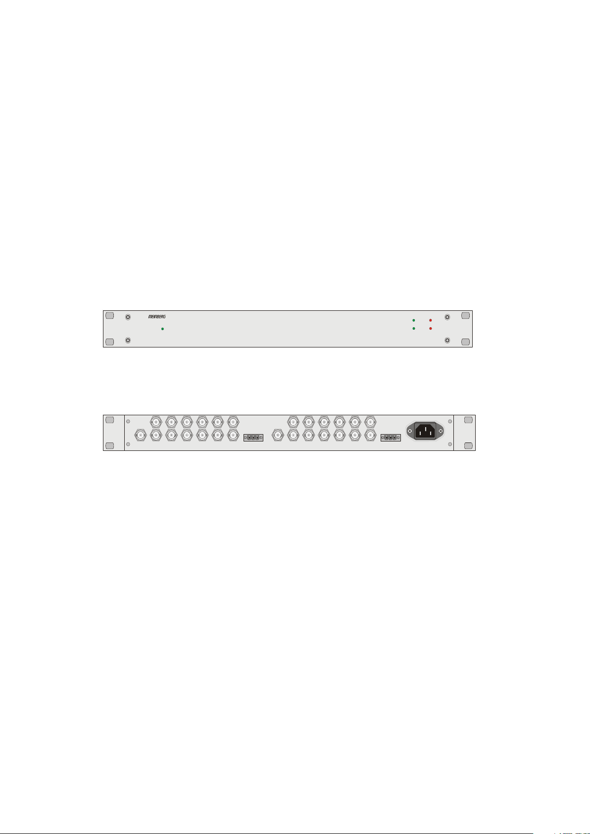
The Signal Distribution Unit SDU is a set of equipment composed of one or two SDU
modules (IRIG-B, TTL or FO) and a power supply module, all installed in a metal
desktop case MULTIPAC and ready to operate.The input/output signales of the SDU
are accessiable via connectors in the back panel of the case.
Details of the components are described below.
SDU in desktop case MULTIPAC
front view
back view
Time Code
modulated
In-1 In-2Out-01
Out-02
Time Code Signal Distribution Unit SDU
POWER
Out-03
Out-05
Out-07
Out-04
Out-06
Out-08
Out-09
Out-10
TTL
Error-1 Error-2
Out-01
Out-03
Out-05
Out-07
Out-11
comm on off comm on off
Out-12
Out-02
Out-04
Out-06
Out-08
Out-09
Out-10
Out-11
Out-12
Module 1
Module 2
Signal
Signal
100 ... 240V AC
50/60 Hz
Alarm
Alarm
4
Page 5

Timecode Distribution SDU/IRIG
The Board SDU/IRIG was designed for the distribution of IRIG-A/B Timecode signals.
It is equipped with an adjustable input amplifier as well as twelve output buffers. The
signal outputs are available via BNC connectors. By means of signal LED's, the status of
the Board is identifiable . Due to the input amplifiers adjustable gain, the boards are
cascadable.
The SDU/IRIG contains a error detection for losing signal output, this ERROR state is
signed by the Alarm LED on the front panel, and by the ERROR output connector on
the back panel.
During "OK" State the connection of the Relay is between: comm - on
During "ERROR" State the connection of the Relay is between: comm - off
The SDU/IRIG is available in two different Modules
Modul TCM: Time Code modulated unbalanced
Modul TCB: Time Code modulated balanced
Specification:
Inputs: IRIG-A/B Signal or similar timecode
with sinusoidal carrier
Input Voltage Range: 0.5Vpp...4Vpp
Input Impedance: 50 Ohm / 600 Ohm, DC-Insulated
Outputs: balanced or unbalanced
12 x IRIG-A/B Signal (or similar Timecode)
unbalanced 3Vpp (MARK), 1Vpp (SPACE) at 50 Ohm for IRIG
common GND for all outputs
balanced 2Vpp at 600 Ohm, with isolated BNC connector
Gain: adjustable automatic Gain control
Connectors:
Inputsignal 1 x BNC isolated connector
Outputsignal 12 x BNC isolated connector
5
Page 6

TTL Distribution Card SDU/TTL
The Board SDU/TTL was designed for the distribution of TTL signals. The input
connection is a BNC connector, the input signal is driven to twelve output buffers, which
are capable of driving 50 Ohm loads. The signal outputs are available via BNC
connectors.
The SDU/TTL contains a ERROR detection for losing signal output, this ERROR
state is signed by the Alarm LED on the front panel, and by the ERROR output
connector on the back panel. For correct error detection on a PPS signal, a minimum
pulse width of 100ms is required, shorter pulse width signals are possible on request.
The insulated input by opto-coupler device is optional possible.
During "OK" State the connection of the Relay is between: comm - on
During "ERROR" State the connection of the Relay is between: comm - off
Specification:
Inputs: TTL Signal (IRIG_DC, PPS, 10MHz, ...)
Isulation by opto-coupler (option)
Input Voltage Range: TTL
Outputs: 12 x TTL
Output Voltage Range: TTL
Output Impedance:
2.5Vat 50 Ohm load
common GND for all outputs
Connectors: 1 x BNC- Connector Inputsignal
12 x BNC- Cconnector Outputsignal
6
Page 7

FO Distribution Module SDU/FO
The module SDU/FO was designed for the distribution of fiber optic signals. The input
signal is connected via a ST type connector, electrically distributed and spread to twelve
output buffers. The signal outputs are available via ST type connectors as well.
The SDU/FO contains a signal detection for the input. This ERROR state is signed by
the Alarm LED on the front panel, and by the ERROR output connector on the back
panel.
During "OK" State the connection of the Relay is between: comm - on
During "ERROR" State the connection of the Relay is between: comm - off
Specification:
Input: Fiber optic signal, 850nm multi mode
for GI 50/125µm or GI 62,5/125µm gradient fiber
(PPS, IRIG-DCLS, 10MHz, ...)
optional: TTL input via BNC connector
optical input level: min. 3µW
Outputs: 12 x fiber optic outputs, 850nm multi mode
for GI 50/125µm or GI 62,5/125µm gradient fiber
Launchable optical
output power: typ. 15µW per output
(into GI 62,5/125µm gradient fiber)
Signal Delay: rise: 70ns
fall: 90ns
Connectors: 1 x ST type connector
12 x ST type connectors
7
Page 8

Technical Specifications SDU /MP
HOUSING: Metal desktop case, MULTIPAC Schroff
Front panel: 1 U / 84 HP (43.6 mm high / 426.4 mm wide)
PROTECTION
RATING: IP20
PHYSICAL
DIMENSIONS: 482,6 mm wide x 43,7 mm high x 280 mm deep
CE Label
This device conforms to the directive 2004/108/EG on the
approximation of the laws of the Member States of the European
Community relating to electromagnetc compatibility.
8
Page 9

Technical Specifications Power Supply MEAN WELL T-60B
LINE INPUT
VOLTAGE: 100 ... 240 VAC
FUSE: electronic
OUTPUT
CURRENT
LIMITING: 105 - 150% I
OUTPUT
VOLTAGE: V
: 5V / 5A
out
CONNECTOR: screw terminal
MOUNTING
FRAME: Metal housing: 159 mm x 97 mm x 38 mm
out nom
AMBIENT
TEMPERATURE: -10 ... +60°C
HUMIDITY: 90% max.
EMC
STANDARDS: CISPR22(EN55022) CLASS B,
IEC801-2,3,4,
IEC555-2 VERIFICATION
Control LEDs
POWER: LED green, output voltage OK
9
Page 10

Technical Specifications Power Supply SD-25A-5 (DC)
LINE INPUT
VOLTAGE: 9 ... 18 VDC
FUSE: electronic
OUTPUT
CURRENT
LIMITING: 105 - 150% I
OUTPUT
VOLTAGE: V
: 5V / 5A
out
TOTAL LOAD: 25Watt max.
CONNECTOR: screw terminal
MOUNTING
FRAME: Metal housing: 98.5 mm x 97 mm x 36.5 mm
out nom
AMBIENT
TEMPERATURE: -10 ... +60°C
HUMIDITY: 90% max.
EMC
STANDARDS: EN55022 class B
EN61000-4-2,3,4,6,8
ENV50204
Control LEDs
POWER: LED green, output voltage OK
10
Page 11

Technical Specifications Power Supply SD-25B-5 (DC)
LINE INPUT
VOLTAGE: 19 ... 36 VDC
FUSE: electronic
OUTPUT
CURRENT
LIMITING: 105 - 150% I
OUTPUT
VOLTAGE: V
: 5V / 5A
out
TOTAL LOAD: 25Watt max.
CONNECTOR: screw terminal
MOUNTING
FRAME: Metal housing: 98.5 mm x 97 mm x 36.5 mm
out nom
AMBIENT
TEMPERATURE: -10 ... +60°C
HUMIDITY: 90% max.
EMC
STANDARDS: EN55022 class B
EN61000-4-2,3,4,6,8
ENV50204
Control LEDs
POWER: LED green, output voltage OK
11
Page 12

Technical Specifications Power Supply SD-25C-5 (DC)
LINE INPUT
VOLTAGE: 36 ... 72 VDC
FUSE: electronic
OUTPUT
CURRENT
LIMITING: 105 - 150% I
OUTPUT
VOLTAGE: V
: 5V / 2.1A
out
TOTAL LOAD: 25Watt max.
CONNECTOR: screw terminal
MOUNTING
FRAME: Metal housing: 98.5 mm x 97 mm x 36.5 mm
out nom
AMBIENT
TEMPERATURE: -10 ... +60°C
HUMIDITY: 90% max.
EMC
STANDARDS: EN55022 class B
EN61000-4-2,3,4,6,8
ENV50204
Control LEDs
POWER: LED green, output voltage OK
12
Page 13

13
Page 14

 Loading...