

Page 1

Technical Information
Operating Instructions
PZF511
Page 2

Impressum
Meinberg Funkuhren GmbH & Co. KG
Lange Wand 9
D-31812 Bad Pyrmont
Phone: +49 (0) 52 81 / 9309-0
Fax: +49 (0) 52 81 / 9309-30
Internet: http://www.meinberg.de
Email: info@meinberg.de
February 24, 2010
Page 3

Table of contents
General information .............................................................................. 5
Features PZF511 .................................................................................. 6
Installation PZF511 .............................................................................. 7
Operating voltage ........................................................................ 7
Antenna ....................................................................................... 7
Assembly of antenna.......................................................... 7
Front panel ............................................................................................ 8
Pilot lamps ............................................................................................ 8
Display ................................................................................................. 9
Control keys ......................................................................................... 9
Menu items ........................................................................................... 9
Menu TIME ................................................................................ 9
Menu DATE ............................................................................. 10
Menu DAY o.W. ...................................................................... 10
Menu PZF STAT ...................................................................... 10
Menu FIELD............................................................................. 11
Menu SETUP............................................................................ 11
Menu DIST. o. T ............................................................. 11
Menu SYNTH. ................................................................ 12
Menu SYNTH M. ........................................................... 12
Menu TIME REF ............................................................ 12
Menu PAR.COMx .......................................................... 13
Menu SER.MODE .......................................................... 13
Menu STR.COMx ........................................................... 13
Menu IRIG ...................................................................... 14
Menu IRIG REF .............................................................. 14
Menu OSZ.ADJ. ............................................................. 15
Menu DAC CLR ............................................................. 15
Menu SER. No. ............................................................... 15
Page 4

Asynchronous serial interfaces ........................................................... 16
Pulse outputs ....................................................................................... 16
Standard frequencies ........................................................................... 16
Frequency synthesizer ........................................................................ 17
Timecode ............................................................................................ 17
Abstract ..................................................................................... 17
Block Diagram Timecode ......................................................... 18
IRIG Standard Format ............................................................... 19
AFNOR Standard Format ......................................................... 20
Assignment of CF Segment in IEEE1344 Code ....................... 21
DC and AM Timecodes ............................................................ 22
Sine Wave AM Output .................................................... 22
PWM DC Output............................................................. 22
DCF77 Emulation .............................................................................. 22
Realtime clock .................................................................................... 23
TIME_SYN output ............................................................................. 23
Firmware updates ............................................................................... 24
Replacing the lithium battery .............................................................. 24
CE Label ............................................................................................ 24
Technical specifications ...................................................................... 25
PZF511 with different oscillator options ................................... 27
Time Strings .............................................................................. 28
Format of the Meinberg Standard Time String................. 28
Format of the ATIS standard Time String........................ 29
Format of the Uni Erlangen String (NTP)........................ 30
Signal description PZF511 ........................................................ 32
Rear Connector Pin assignment................................................. 33
Menüstruktur PZF511 ........................................................................ 35
Page 5

General information
The German long wave transmitter DCF77 started continious operation in 1970. The
introduction of time codes in 1973 build the basic for developing modern radio remote
clocks.
The carrier frequency of 77.5kHz is amplitude modulated with time marks each
second. The BCD-coding of the time telegram is done by shifting the amplitude to 25%
for a period of 0.1s for a logical '0' and for 0.2s for a logical '1'. The receiver reconstructs
the time frame by demodulating this DCF-signal. Because the AM-signal is normally
superimposed by interfering signals, filtering of the received signal is required. The
resulting bandwidth-limiting causes a skew of the demodulated time marks which is in
the range of 10ms. Variations of the trigger level of the demodulator make the accuracy
of the time marks worse by additional +/-3ms. Because this precision is not sufficient for
lots of applications, the PTB (Physical and Technical Institute of Germany) began to
spread time informations by using the correlation technique.
The DCF-transmitter is modulated with a pseudo-random phase noise in addition to
the AM. The pseudo-random sequence (PZF) contains 512 bits which are transmitted by
phase modulation between the AM-time marks. The bit sequence is build of the same
number of logical '0' and logical '1' to get a symmetrical PZF to keep the average phase of
the carrier constant. The length of one bit is 120 DCF-clocks, corresponding to 1,55ms.
The carrier of 77.5kHz is modulated with a phase deviation of +/-10° per bit. The bit
sequence is transmitted each second, it starts 200ms after the beginning of a AM second
mark and ends shortly before the next one.
Compared to an AM DCF77-receiver, the input filter of a correlation receiver can be
dimensioned wide-bandwidth. The incoming signal is correlated with a reconstructed
receiver-PZF. This correlation analysis allows the generation of time marks which have
a skew of only some microseconds. In addition, the interference immunity is increased
by this method because interference signals are suppressed by averaging the incoming
signal. By sending the original or the complemented bit sequence, the BCD-coded time
information is transmitted.
The absolute accuracy of the generated time frame depends on the quality of the
receiver and the distance to the transmitter, but also on the conditions of transmission.
Therefore the absolute precision of the time frame is better in summer and at day than in
winter and at night. The reason for this phenomenon is a difference in the portion of the
sky wave which superimposes the ground wave. To check the accuracy of the time
frame, the comparison of two systems with compensated propagation delay is meaningful.
5
Page 6

Features PZF511
The PZF511 is a high precision receive module for the DCF77-signal build in eurocard
size (100mm x 160mm). The 61mm wide front panel contains an eight digit alphanumeric display, three LEDs and two keys as control actuators.
The microcontroller of the system correlates its receiver-PZF with the incoming
pseudorandom sequence and decodes the time information of the DCF-telegram simultaneously. The controller handles input and output functions of the PZF511 and synchronizes the internal realtime clock.
By evaluating the pseudorandom phase noise, the PZF511 is able to generate time
frames with thousand times the accuracy of standard AM-time code receiver. The precise
regulation of the main oscillator of the radio clock is possible therefore. So, the PZF511
can be used as a standard frequency generator besides the application as a time code
receiver. Four fixed and one settable TTL-level standard frequencies are available at the
rear VG-connector. The synthesizer frequency exists as an open drain output and a
sinewave signal also.
As an addition to the previous PZF510 the PZF511 generates an IRIG timecode that is
available at the rear VG-connector both as a modulated AM and as an unmodulated
DCoutput.
Furthermore the PZF511 provides active-low as well as active-high TTL pulses per
minute and per second. To distribute informations concerning date, time and status, three
independant serial interfaces (RS232) are used which are configurable in a setup menu.
Like mentioned before, the PZF511 includes a battery-backed realtime clock which
runs crystal-precise if the main power supply fails.
Important system parameters are stored in a battery-backed RAM or non-volatile
(EEPROM) memory.
If an update of system software becomes necessary, the new firmware can be loaded
via serial interface (COM0) without removing the PZF511 for inserting a new EPROM.
6
Page 7

Installation PZF511
To achieve the technical data given in chapter 'technical specifications', the following
points must be observed.
Operating voltage
The clock operates with a single +5V supply. The output voltage should be well
regulated because drifting supply voltages reduce the short time accuracy of the generated frequencies and timing pulses. The power supply lines should have low resistance
and be connected using both pins a and c of the rear connector.
Antenna
The external ferrite antenna AW02 is connected to the receiver by using a 50 ohm coax
cable. If reception is sufficient, the length of the cable can be up to several hundred
meters without any problems. An antenna amplifier is available for very long antenna
cables.
Assembly of antenna
The antenna has to be mounted as exactly as possible. Turning it out of the main receive
direction will result in less accurate time frames. The antenna must be placed in
longitudinal direction to the DCF-transmitter (Frankfurt). The nearness to microcomputers should be avoided (PZF511 included) and the antenna should be installed with a
minimum distance of 30cm to all metal objects, if possible. A distance of several meters
to TV- or computermonitors must be kept.
After switching the PZF511 to the menu 'FIELD', the adjustment of the antenna can
be executed. The displayed value is proportional to the received field strength. The best
method of mounting the antenna is to look for the minimum field strength and turn the
antenna by 90° to maximum then. A high field strength on its own is no guarantee for
good conditions of receiption, because interfering signals within the bandwidth of the
receiver also have an effect on the displayed value.
The maximum interference immunity can be found by looking at the autocorrelation
coefficient (in percent) in the menu 'PZF-STAT'. The displayed value should be close to
100% for best receiption.
7
Page 8
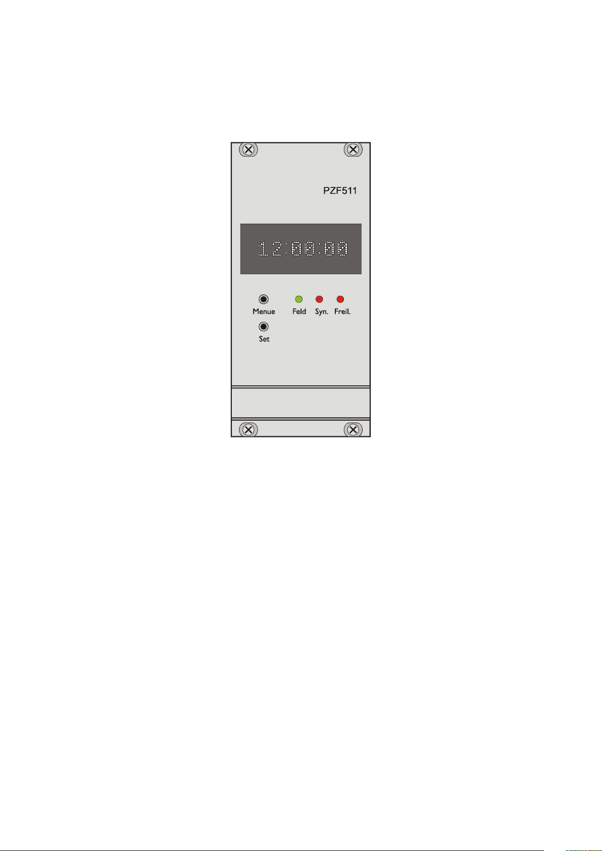
Front panel
Pilot lamps
The 'Feld'-LED is switched on if a DCF-signal with at least minimum field strength
needed for the correlation receiption is detected at the input of the receiver.
The 'Syn.'-LED indicates that the autocorrelation coefficient decreases beyond a value
that is needed and a correct receiption is not possible therefore. This happens if a strong
interferer within the bandwidth of the receiver is present or the transmitter is switched of.
If the 'Freil.'-LED is on, it was not possible to synchronize the internal realtime clock
to DCF-time. This condition occures for at most two minutes after switching on the
PZF511, because two DCF-telegrams are checked for plausibility before the data is
taken over. Short disturbance of receiption can cause this state too.
8
Page 9
Display
The eight digit alphanumeric display shows important information concerning status and
time. The setting of system parameters is also done with the help of the display.
Control keys
It is possible to change the displayed information (time, date or status information) by
two keys. The 'Menu'-key selects one of several menus. After presing the 'Set'-button the
belonging information appears on the display. Furthermore, the keys are used to set userspecific parameters in several submenus.
Menu items
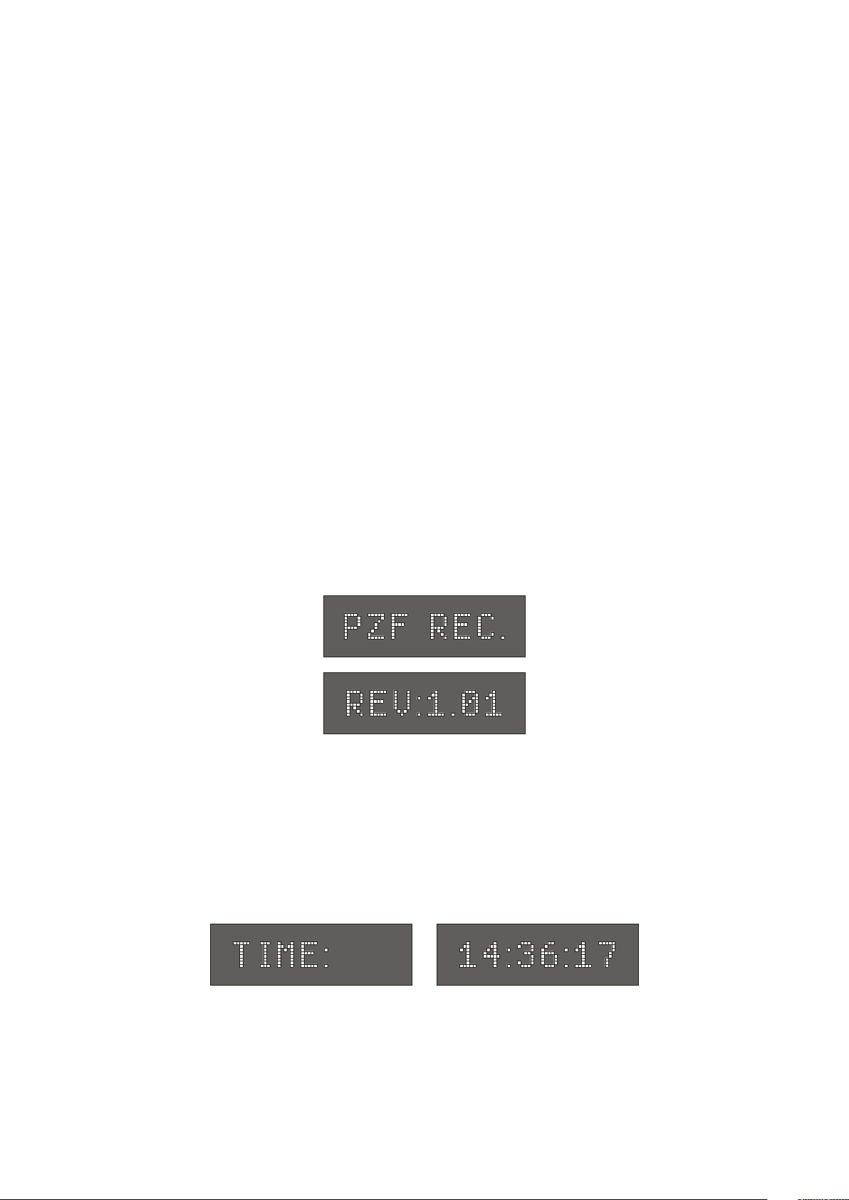
The type of DCF-clock and the software revision are displyed first after power-up. The
following informations are readable before the PZF511 switches to time-display automatically:
The handling of any queries will be simplified if the software revision is given by the
user. The following menus are available then:
Menu TIME
In this menu the current time is displayed (this is the default after power up).
9
Page 10
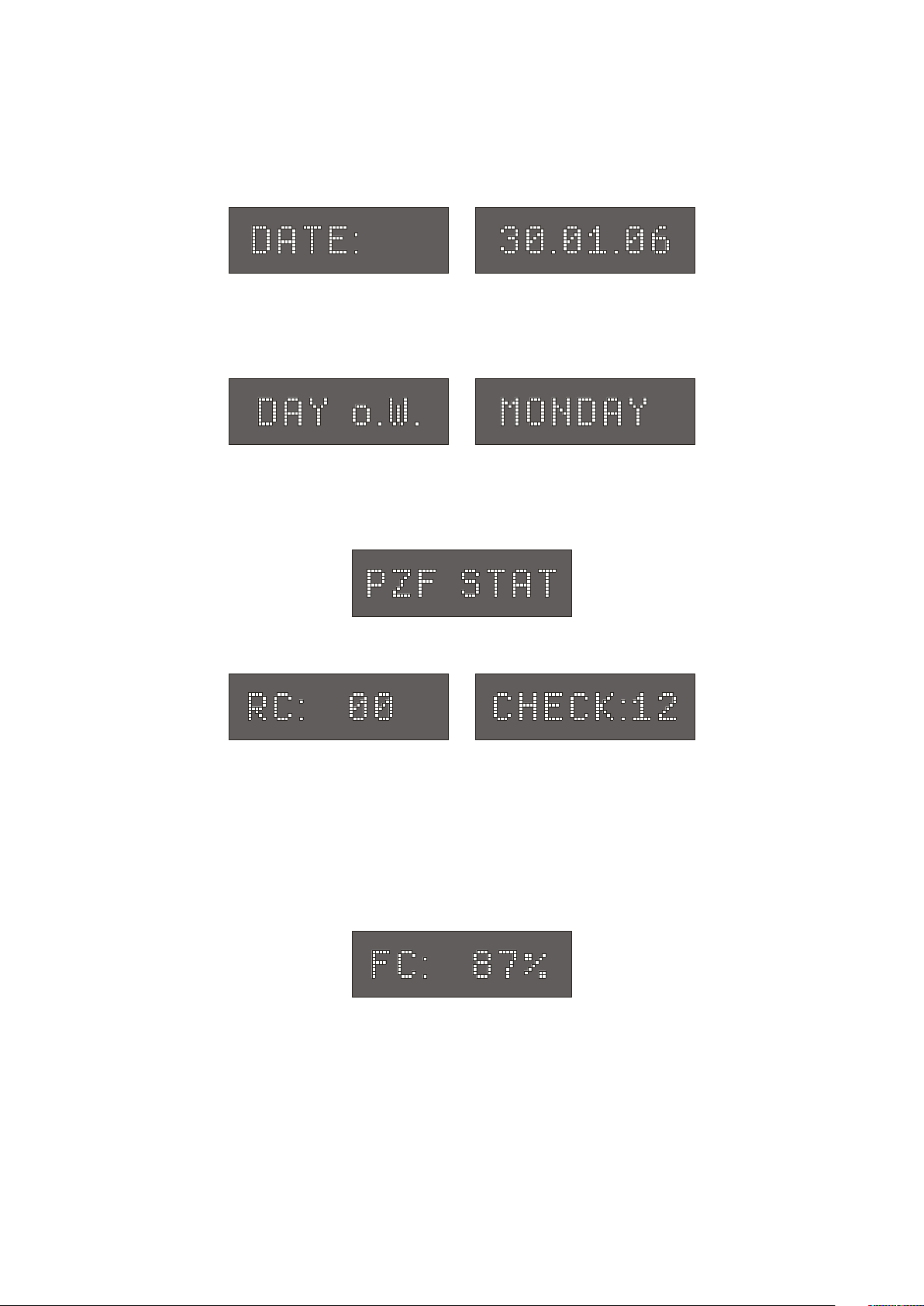
Menu DATE
After the Set button is pressed, the actual date appears on the display.
Menu DAY o.W.
The day of the week will be displayed in this menu.
Menu PZF STAT
Information on the decoding of the pseudo-random sequence is available in this menu.
The following texts may be displayed:
This message indicates that the system tries to achieve a coarse synchronisation. This
procedure starts after power-up or worse receiption for more than ten seconds. If the
coarse synchronisation was successfull, the receiver enters the state of fine-correlation.
The system tries to lock the received PZF as exact as possible to generate a precise time
frame. The display shows the correlation coefficient at the end of each second, which can
be up to 100%. A high value for the coefficient should be achieved by choosing a
suitable position for the antenna.
The essential part of the tracking is completed five seconds after "FC: xx%" appeared
and the generation of pulses per minute and per second starts. Tracking steps of three
microseconds are possible each second until the internal realtime clock is synchronized
(two minutes max.). Afterwards, corrections of the time frame are executed per minute
only. The direction of these steps is displayed by the characters '>' or '<' behind the digits
of the correlation coefficient.
10
Page 11
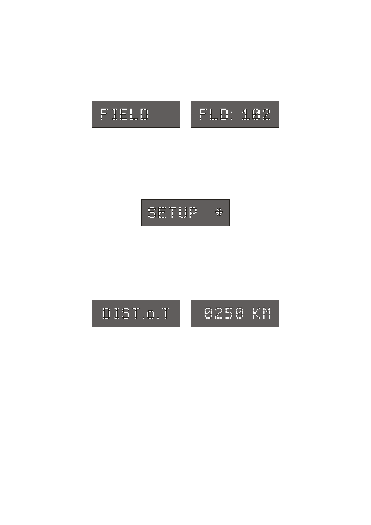
Menu FIELD
The digitized value of the field strength is displayed in this menu. There is a logarithmic
relation between this value and the field strength. This menu is useful for mounting the
antenna, like described in chapter 'Assembly of antenna'.
Menu SETUP
The user-specific parameters of the PZF511 are set in this menu. To avoid the erroneous
change of these parameters, it is not possible to enter the submenus by a simple pressing
of the Set-button. The first submenu is entered if the Set-button is pressed until the
character '*' is displayed behind the text SETUP and the Menu-key is actuated then.
The following submenus are selectable (Set-button and Menu-key used as usual now):
Menu DIST. o. T
The distance to the transmitter is entered in this menu for compensating the propagation
delay of the received pseudo-random code. This setting should be done as exact as
possible because the absolute precision of the time frame is influenced by this value.
After pressing the Set-button a four digit kilometer-value is displayed. By pressing the
Set-key again, the first position is selected (flashing digit). To choose a different digit, the
Menu-key has to be pressed, to increment the current digit the Set-button must be used. If
the value is entered, it will be stored by pressing the Menu-key until the display returns to
the setup submenu. The km-value is stored in the internal EEPROM of the board.
11
Page 12

Menu SYNTH.
The output frequency of the internal synthesizer is selected in this menu. This can be
done in the range of 1/3Hz to 9.999MHz.
The frequency can be set here and the buttons are used the same way as for setting the
DIST.o.T-value. In addition, the range of the frequency is defined and eiter xxx.xHz,
x.xxxkHz, xx.xxkHz, xxx.xkHz or x.xxxMHz can be selected. In the first range (Hz)
only the fractional digits 1/3Hz, 0.5Hz and 2/3Hz are accepted. After the frequency is
entered the value becomes valid and is stored in the battery buffered RAM just after the
Menu-button is pressed a longer time. Note: the sinewave output of the synthesizer
provides an acceptable output signal not above 100kHz.
Menu SYNTH M.
This menu configueres at which time after power-up the frequency generation of the
synthesizer starts. The following settings are possible:Frequency-generation immediately after reset (allways),
or the clock has to synchronize first before generation of the frequency starts (after
synchronisation). Frequencies less than 10kHz are phase locked to the precise pulse per
second at once.
Selection of the values happens like described.
Menu TIME REF
The displayed timezone can be set in this menu. Possible selections are:: UTC, MEZ/
MESZ and MEZ (without daylight saving).
12
Page 13

Menu PAR.COMx
The three menus PAR.COM0 to PAR.COM2 allow the configuration of the serial
RS232 ports COM0 to COM2.
The following settings are possible:
Baudrate: 600, 1200, 2400, 4800, 9600 and 19200 Baud
Framing: 7N2, 7E1, 7E2, 8N1, 8N2, 8E1, 7O2 and 8O1
Menu SER.MODE
The three serial ports COM0 to COM2 are able to send a time string in three different
output modes. After the Set button is pressed the following is displayed:
The three letters on the right side represent the output mode of the serial ports COM0,
COM1 and COM2 (from the left to the right). With another brief push of the Set button
the first letter starts to blink and can be set to one of the following values now:
'S' timestring starts with a new second
'M' timestring starts with a new minute
'R' timestring starts just after sending an ASCII '?' (3F hex) to the clock
Menu STR.COMx
The three menus STR.COM0 to STR.COM2 allow the selection of the serial time strings
for COM0, COM1 and COM2.
The following time strings can be selected:
- MBG - Meinberg Standard String
- Uni Erlangen String
- ATIS String
13
Page 14

Menu IRIG
This menu allows to select an IRIG, AFNOR or IEEE1344 timecode to be generated.
Besides the amplitude modulated sine wave signal, the PZF511 also provides an
unmodulated DC-Level Shift TTL output in parallel. Thus six time codes are available.
a) B002: 100pps, PWM DC signal, no carrier
BCD time-of-year
b) B122: 100pps, AM sine wave signal, 1 kHz carrier frequency
BCD time-of-year
c) B003: 100pps, PWM DC signal, no carrier
BCD time-of-year, SBS time-of-day
d) B123: 100pps, AM sine wave signal, 1 kHz carrier frequency
BCD time-of-year, SBS time-of-day
e) AFNOR: Code according to NFS-87500, 100pps,
AM-Sine wave signal, 1kHz carrier frequency,
BCD time-of-year, complete date, SBS time-of-day,
Signal level according to NFS-87500
f) IEEE1344: Code according to IEEE1344-1995, 100pps,
AM sine wave signal, 1kHz carrier frequency,
BCD time-of-year, SBS time-of-day, IEEE1344
extensions for date, timezone, daylight-saving
and leap second in control functions (CF) segment.
also see table 'Assignment of CF segment in IEEE1344 mode'
Menu IRIG REF
This menu lets the user select a timezone for the timecode generation.
14
Page 15

Menu OSZ.ADJ.
The standard version of the PZF511 includes a voltage controlled temperature compensated oszillator (TCXO). Its nominal frequency of 10MHz is adjusted by using two
digital-to-analog converters (DACs). One of them is responsible for the coarse tuning
and the other one for the fine adjustment of the oszillator.
The value for the coarse-DAC is settable in this menu (range: 0...65535).
Changes in this menu should be done by Meinberg, only, and not by the user!
Menu DAC CLR
The value of the fine DAC is displayed in this submenu.
If the 'Set'-button is pressed for approximately two seconds, the DAC is set to its midscale value and the difference to its last value is added to the coarse DAC proportional.
This process is released automatically if the value of the fine DAC exceeds its limits
(0...4095).
Therefore the setting of this value to mid-scale by hand is reserved for service
purposes by Meinberg only.
Menu SER. No.
The 12-digit serial number of the PZF511 is displayed in this menu. This number may be
helpful to know if the user asks Meinberg for support.
The most significant eight digits of the serial number are displayed first, after pressing the
Set button the last four digits are shown.
15
Page 16

Asynchronous serial interfaces
Three independant serial RS232 interfaces are available at the rear connector of the clock
PZF511. As set in menu SER.MODE, the serial ports can send the a time string either
per second, per minute or on request by sending an ASCII '?' (3F hex) to the clock.
Additional menus are used to set the framing and baudrate of these interfaces as well as
the format of the time string. The structure of the strings are described in the chapter
"Time Strings".
Pulse outputs
TTL-low and TTL-high active pulses per minute and per second are generated by the
PZF511, which are available at the VG-connector. TTL-high active pulses per 15
minutes (P_15MIN) are also available at the VG-connector.
Because the internal time frame of the clock has not yet been synchronized with the
pseudo random sequence, no pulses are generated directly after reset. In case of normal
receiption, the receiver needs about 12 seconds for coarse and another 5 seconds for fine
synchronization. So, pulses are generated approximately 17 seconds after reset.
Standard frequencies
The PZF511 provides four standard frequencies. The outputs 100kHz, 155kHz, 1MHz
and 10MHz are derived from the main oszillator of the clock which is phase locked to the
DCF-system by a digital PLL (phase locked loop). The temperature-dependant drift and
the aging of the oszillator can be compensated by this procedure. Therefore the excellent
short-term stability of the standard frequencies of +/- 5·10
TCXO) is achieved. The value for regulating the digital-to-analog converter of the PLL
is avilable directly after reset because it is stored in the battery-backed RAM of the clock.
If the DCF-transmitter fails, the oszillator is controled by this value also. The accuracy of
the standard frequencies will not be worse than 1·10
-8
therefore.
-9
(standard version with
for one hour without receition
16
Page 17

Frequency synthesizer
The synthesizer of the PZF511 generates a frequency in the range of 1/3Hz up to
9.999MHz, which can be set in the menu SYNTH. The synthesizer-output is available
with TTL-level, as a sinewave signal or an open drain output at the VG-connector.
However, the sine wave output generates an acceptable output signal up to 100kHz,
only.
The frequency to be generated can be adjusted by giving the four digits of highest-order,
lower significant digits are set to zero. Only the fractions 1/3Hz, 0.5Hz and 2/3Hz are
allowed in the Hertz-range, so frequencies of 1/3Hz or 2/3Hz lead to a periodic fraction,
often used by ripple control systems.
Up to a value of 10kHz the synthesizer is phase-locked to the pulse per second. The
accuracy of this frequency reaches the exactness of the standard frequencies therefore.
Higher frequencies than 10kHz have a maximum error of +/- 2,35 mHz.
The behaviour of the synthesizer after power-up is selectable (see menu SYNTH. M),
Frequency generation can start either directly after reset or after synchronization.
Timecode
Abstract
The transmission of coded timing signals began to take on widespread importance in
the early 1950´s. Especially the US missile and space programs were the forces behind
the development of these time codes, which were used for the correlation of data. The
definition of time code formats was completely arbitrary and left to the individual ideas of
each design engineer. Hundreds of different time codes were formed, some of which
were standardized by the "Inter Range Instrumentation Group" (IRIG) in the early 60´s.
Except these "IRIG Time Codes", other formats like NASA36, XR3 or 2137 are still
in use. The board PZF511 however generates the IRIG-B, AFNOR NFS 87-500 code
as well as IEEE1344 code which is an IRIG-B123 code extended by information for
time zone, leap second and date.
17
Page 18

Block Diagram Timecode
modulated timecode
driver
50 unbalanced
D/A converter
modulator
high- and low-active
unmodulated timecodes
timecode
microcontroller
digital
sinewave
EPLD
generator
PPS
10 MHz
18
Page 19

IRIG Standard Format
x 3x
IRIB-B : 1000 Hz
binary 0 binary 1
TYPICAL MODULATED CARRIER IRIG-A : 10000 Hz
19
Page 20

AFNOR Standard Format
20
Page 21

Assignment of CF Segment in IEEE1344 Code
B it N r. B e de utung B e s c hre ibung
49 Po sition Ide ntifier P 5
50 Year BCD encoded 1
51 Year BCD encoded 2
unter es N ib ble d e s B C D c od ier ten J a hre s
52 Year BCD encoded 4
53 Year BCD encoded 8
54 empty, always zero
55 Year BCD encoded 10
56 Year BCD encoded 20
oberes Nibble des BCD codierten Jahres
57 Year BCD encoded 40
58 Year BCD encoded 80
59 Position Identifier P6
60 LS P - L ea p S ec o nd P end ing bis zu 5 9 s vo r S c ha ltsek und e ges e tzt
61 LS - Leap Seco nd 0 = LS einfügen, 1 = LS löschen
1.)
62 DS P - Da ylight Sa ving Pe nd ing b is zu 59 s vor S Z/W Z U msc ha ltung ges etzt
63 DS T - Da ylight Sa ving Time ges et zt wä hre nd S o mmer zeit
64 Timezone Offset Sign Vorzeichen des Zeitzonenoffsets 0 = '+', 1 = '-'
65 TZ Offset binary encoded 1
66 TZ Offset binary encoded 2
O ffset de r IRIG Ze it gegenüber U TC
I R I G Z e it PL U S Z e it zo n e n o ffse t ( e in s c h lie ßlic h
67 TZ Offset binary encoded 4
Vo rzeichen ) ergibt immer UTC
68 TZ Offset binary encoded 8
69 Position Identifier P7
70 TZ O ffset 0 . 5 hour ges et zt be i zusät zliche m halbs tünd igen Offset
71 TFO M Time figure of merit
72 TFO M Time figure of merit
TF O M gibt d e n ungefä hre n F ehler de r
Z e it q u e lle an
2.)
0x00 = Uhr synchron
73 TFO M Time figure of merit
0 x 0 F = U hr im F r e ila u f
74 TFO M Time figure of merit
75 PA RI TY P ar ität a ller vo ra ngega nge ne n Bits
1.)
von d er Firmwa re we rd en nur e ingefügte Sc haltsek und en ( 5 9 - > 60 - > 00 ) unte rstützt !
2.)
TF O M wird a uf 0 ge se tzt w enn d ie U hr na c h de m Einsc ha lten e inmal synchro nisier en k o nnte , a nd er e
C o d ierunge n we rd e n vo n de r F irmw a re nicht unte rst üzt. s.a. Auswahl des generierten Zeitcodes.
21
Page 22

DC and AM Timecodes
DC-Level Shift Codes (PWM-signal) B00x and modulated sine wave carrier B12x are
always generated simultaneously. Both signals are provided at the VG64-Connector, i.e.
if code B132 is selected per menu, also code B002 is available. This applies for the codes
AFNOR NFS 87-500 and IEEE1344 as well.
The TFOM field in IEEE1344 code is set dependent on the 'already sync'ed' character
('#') which is sent in the serial time telegram. This character is set, whenever the
preconnected clock was not able to synchronize after power up reset. The 'time figure of
merit' (TFOM) field is set as follows.
Clock synchronized once after power up : TFOM = 0000
Clock not synchronized after power up : TFOM = 1111
Sine Wave AM Output
The amplitude-modulated carrier is available at the VG-connector pin 14a. The carrier
frequency is 1kHz (IRIG-B). The signal amplitude is 3Vpp (MARK) and 1Vpp (SPACE)
into 50 Ω. The encoding is made by the number of MARK-amplitudes during ten carrier
waves with the following agreements:
a) binary "0" : 2 MARK-amplitudes, 8 SPACE-amplitudes
b) binary "1" : 5 MARK-amplitudes, 5 SPACE-amplitudes
c) position-identifier : 8 MARK-amplitudes, 2 SPACE-amplitudes
PWM DC Output
The pulse width modulated DC signals shown in the diagramms "IRIG" and "AFNOR
standard format" are coexistent to the modulated output and is available at the VG
connector pin 13a with TTL level.
DCF77 Emulation
The correlation receiver PZF511 generates TTL level time marks (active HIGH) which
are compatible with the time marks spread by the German long wave transmitter DCF77.
This long wave transmitter installed in Mainflingen near Frankfurt/Germany transmits
the reference time of the Federal Republic of Germany: time of day, date of month and
day of week in BCD coded second pulses. Once every minute the complete time
information is transmitted. The PZF511 generates time marks representing always the
22
Page 23

DCF-time including announcement of changes in daylight saving and announcement of
leap seconds, changing the timezone in the setup menu has no effect on the generation.
The coding sheme is given below:
P
8
3
M
4
Kalenderjahr
Kalender-
monat
Wochentag
Kalendertag
0
0
2
0
1
0
8
4
2
1
1
0
50
8
4
2
1
4
2
1
40
0
2
0
1
8
4
2
1
0
30
2
0
P
2
0
1
Stunde
P
8
1
1
4
2
Kodierung
nach Bedarf
10
R
A
1
Z
1
Z
2
20
A
2
S
1
2
4
8
1
0
2
4
0
Minute
0
MMinutenmarke (0.1 s)
R Aussendung über Reserveantenne
A1 Ankündigung Beginn/Ende der Sommerz eit
Z1, Z2 Zonenzeitbits
Z1, Z2 = 0, 1: Standardzeit (MEZ)
Z1, Z2 = 1, 0: Sommerzeit (MESZ)
A2 Ankündigung einer Schaltsekund e
S Startbit der codier ten Zeitinformation
P1, P2, P3 gerade Paritätsbits
Time marks start at the beginning of new second. If a binary "0" is to be transmitted, the
length of the corresponding time mark is 100 msec, if a binary "1" is transmitted, the time
mark has a length of 200 msec. The information on the current date and time as well as
some parity and status bits can be decoded from the time marks of the 15th up to the 58th
second every minute. The absence of any time mark at the 59th second of a minute
signals that a new minute will begin with the next time mark. The DCF emulation output
is enabled immediately after power-up.
Realtime clock
The PZF511 includes a battery-backed realtime clock which runs crystal-precise in case
of power failure. A relativ accurate time is present immediately after power-up this way.
An additional RAM of the realtime clock is used to store important system parameters.
TIME_SYN output
This output is set to TTL-high if the receiver is in synchronous state (LED 'Freil'
switched off). The output level changes to TTL-low if the receiver is in asynchronous
state for more than one hour. The TIME_SYN output is available at the VG-connector
and can be used to release an alarm, for example.
23
Page 24

Firmware updates
Whenever the on-board software must be upgraded or modified, the new firmware can
be downloaded to the internal flash memory via the serial port COM0. There is no need
to remove the board to insert a new EPROM.
If the 'Menu' key on the front panel is pressed or the pin '/BOOT' at the bladeconnector strip is held at TTL-low level while the system is powered up, a bootstraploader is actived and waits for instructions from the serial port COM0. The new firmware
can be sent to PZF511 from any standard PC with serial interface. A loader program will
be shipped together with the file containing the image of the new firmware.
The contents of the program memory will not be modified until the loader program has
sent the command to erase the flash memory. So if the 'Menu' key is pressed unintentionally while the system is powered up, the firmware will not be changed accidentially.
After the next power-up, the system will be ready to operate again.
Replacing the lithium battery
The life time of the lithium battery on the board is at least 10 years. If the need arises to
replace the battery, the following should be noted:
ATTENTION!
Danger of explosion in case of inadequate replacement
of the lithium battery. Only identical batteries or batte-
ries recommended by the manufacturer must be used for
replacement. The waste battery must be disposed as
proposed by the manufacturer of the battery.
CE Label
This device conforms to the directive 2004/108/EG on the
approximation of the laws of the Member States of the European
Community relating to electromagnetc compatibility.
24
Page 25

Technical specifications
RECEIVER: Two seperate receiver channels for signal conversion and best
aquisition and tracking of the DCF77 signal.
Reception via external ferrite antenna AW02.
CONTROL OF
RECEPTION: The DCF-signal is checked for minimum field strength by micro-
processor. The result is indicated by LED.
In addition, the value of the digitized field strength is displayed in
menu 'FIELD'.
BATTERYBACKUP: In case of power failure an internal realtime clock runs crystal-
precise. Important parameters are stored in the system-RAM.
Life time of lithium battery: 10 years minimum
Option: backup capacitor for about 150 hours
DISPLAY: Eight-digit alphanumeric display shows important time and status
information. Digit-height 5mm.
INTERFACES: Three independent RS232 ports
BAUD RATES: 600, 1200, 2400, 4800, 9600 or 19200 Baud
FRAMING: 7N2, 7E1, 7E2, 8N1, 8N2, 8E1, 7O2 or 8O1
PULSE
OUTPUTS: Active-high and active-low pulses per minute and per second,
TTL-level, pulse duration: 200ms
Active-high pulses per 15 minutes, TTL, pulse duration: 200ms
ACCURACY
OF PULSES: Time delay of two systems PZF511 with a maximum distance of
50km: typ. 20µs, max. 50µs
Time shifting of successive pulses: max. 1.5µs
PROPAGATIONTIME
COMPENSATION:The signal delay is compensated if the distance of the receiver to
the transmitter is given.
25
Page 26

STANDARD
FREQUENCIES: 100kHz, 155kHz, 1MHz and 10MHz are synchronized to DCF
by a digital PLL.
For accuracy refer to table "Oscillator Types".
SYNTHESIZER: Frequency range: 1/3Hz...9,999MHz
Accuracy: < 10kHz: refer to table "Oscillator Types"
> 10kHz: +/- 2,35mHz max.
Phase jitter: max. 60ns
SYNTHESIZEROUTPUTS: F_SYNTH: TTL-level
F_SYNTH_OD: Open Drain
Max. drain-source-voltage: 100 V
Max. drain-current: 100 mA
Dissipation power, 25° C: < 360 mW
F_SYNTH_SIN: Sinewave
Output voltage: 1.5 V eff.
Output impedance: 200 Ohm
TIMECODEOUTPUTS: AM: Unbalanced AM-sine wave-signal:
3VPP (MARK) / 1VPP (SPACE) into 50Ω
DC: PWM signal, TTL, high active
TIME_SYN
OUTPUT: TTL-level, logical-high if receiver is synchronous
TERMINAL
CONNECTION: Blade-connector strip VG64, DIN 41612
Sub-miniatur coaxial HF-connector (SMB)
BOARD
DIMENSIONS: Eurocard size 100mm x 160mm, Epoxy 1,5mm
Front panel 12TE (61mm)
ANTENNA: Ferrite antenna in plastic housing
HUMIDITY: Relativ humidity 85% max.
TEMPERATURE
RANGE: 0 ... 50°C
POWER
SUPPLY: + 5V, 230mA
26
Page 27

PZF511 with different oscillator options
The correlation receiver PZF511 can be equipped with several different oscillator types.
Compared with the standard version (TCXO) the accuracy specifications are changed as
given in the following table:
OXCTOXCT
OXCTOXCT QLOXCOQLOXCO
OXCT
τ ces1=
ytilibatsmrettrohs
nureerfycarrucca
yadeno
nureerfycarrucca
raeyeno
esionesahp
C°52taylppusrewop
etatsydaets
pumraw
nureerf
tfirdtnadnepederutarepmet
sepyTrotallicsO:1elbaTsepyTrotallicsO:1elbaT
sepyTrotallicsO:1elbaTsepyTrotallicsO:1elbaT
sepyTrotallicsO:1elbaT
9-E01*49-E01*201-E01*411-E01*2
7-E01*1-/+
)1etoN(zH1-/+
6-E01*1-/+
)1etoN(zH01-/+
zH1
zH01
zH001
zHk1
zH/cBd06zH/cBd09-
zH/cBd021zH/cBd031-
Am02/V5+
A/N
6-E01*1-/+
)C°07...02-(
zH1
zH01
zH001
zHk1
QLOXCOQLOXCO QMOXCOQMOXCO
QLOXCO
8-E01*2-/+
)1etoN(zH2.0-/+
7-E01*4-/+
)1etoN(zH4-/+
zH/cBd06zH/cBd09-
cBd021-
zH/
zH/cBd031-
Am061/V5+
Am083/V5+
7-E01*2-/+
)C°06...0(
zH1
zH01
zH001
zHk1
zH1-/+=zHM01*7-E01*1-/+si)yadenonureerf(OXCTfoycarruccA
QMOXCOQMOXCO QHOXCOQHOXCO
QMOXCO
9-E01*5,1-/+
)1etoN(zHm51-/+
7-E01*1-/+
)1etoN(zH1-/+
zH/cBd57-
zH/cBd011zH/cBd031zH/cBd041-
Am09/V5+
Am033/V5+
8-E01*5-/+
)C°07...02-(
:elpmaxeroF.zHM01foycneuqerfdradnatsehtnodesabsiztreHniycarruccaehT
QHOXCOQHOXCO
QHOXCO
01-E01*5-/+
)1etoN(zHm5-/+
8-E01*5-/+
)1etoN(zH5.0-/+
zH1
zH01
zH001
zHk1
zH/cBd59-
zH/c
Bd521-
zH/cBd541zH/cBd551-
Am061/V5+
Am006/V5+
8-E01*1-/+
)C°07...5(
27
Page 28

Time Strings
Format of the Meinberg Standard Time String
The Meinberg Standard Time String is a sequence of 32 ASCII characters starting with
the STX (start-of-text) character and ending with the ETX (end-of-text) character. The
format is:
<STX>D:dd.mm.yy;T:w;U:hh.mm.ss;uvxy<ETX>
The letters printed in italics are replaced by ASCII numbers whereas the other characters
are part of the time string. The groups of characters as defined below:
<STX> Start-Of-Text (ASCII code 02h)
dd.mm.yy the current date:
dd day of month (01..31)
mm month (01..12)
yy year of the century (00..99)
w the day of the week (1..7, 1 = Monday)
hh.mm.ss the current time:
hh hours (00..23)
mm minutes (00..59)
ss seconds (00..59, or 60 while leap second)
uv clock status characters (depending on clock type):
u: ‘#’ GPS: clock is running free (without exact synchr.)
PZF: time frame not synchronized
DCF77: clock has not synchronized after reset
‘ ‘ (space, 20h)
GPS: clock is synchronous (base accuracy is reached)
PZF: time frame is synchronized
DCF77: clock has synchronized after reset
v: ‘*’ GPS: receiver has not checked its position
PZF/DCF77: clock currently runs on XTAL
‘ ‘ (space, 20h)
GPS: receiver has determined its position
PZF/DCF77: clock is syncronized with transmitter
x time zone indicator:
‘U’ UTC Universal Time Coordinated, formerly GMT
‘ ‘ MEZ European Standard Time, daylight saving disabled
‘S’ MESZ European Summertime, daylight saving enabled
y anouncement of discontinuity of time, enabled during last hour
before discontinuity comes in effect:
‘!’ announcement of start or end of daylight saving time
‘A’ announcement of leap second insertion
‘ ‘ (space, 20h) nothing announced
<ETX> End-Of-Text (ASCII code 03h)
28
Page 29

Format of the ATIS standard Time String
The ATIS standard Time String is a sequence of 23 ASCII characters terminated by a
CR (Carriage Return) character. The format is:
<GID><ABS><TSQ><CC><CS><ST>yymmddhhmmsswcc<GID><CR>
The letters printed in italics are replaced by ASCII numbers whereas the other characters
are part of the time string. The groups of characters as defined below:
<GID> Address of the receiver code 7Fh
<ABS> Originator of message ASCII '0' code 30h
<TSQ> Telegram number ASCII '0' code 30h
<CC> Command code ASCII 'S' for SET code 53h
<CS> Command code ASCII 'A' for ALL code 41h
<ST> Time status ASCII 'C' for valid time code 43h
yymmdd the current date:
yy year of the century (00..99)
mm month (01..12)
dd day of month (01..31)
hh:mm:ss the current time:
hh hours (00..23)
mm minutes (00..59)
ss seconds (00..59, or 60 while leap second)
w the day of the week (1..7, 1 = 31h = Monday)
cc checksum in hex, built from all characters including GID, ABS,
TSQ, CC, ST, ...
<CR> Carriage Return, ASCII code 0Dh
Default RS232 Settings:
Baudrate: 2400 Bd, Framing: 7E1
29
Page 30

Format of the Uni Erlangen String (NTP)
The time string Uni Erlangen (NTP) is a sequence of 66 ASCII characters starting with
the STX (start-of-text) character and ending with the ETX (end-of-text) character. The
format is:
<STX>tt.mm.jj; w; hh:mm:ss; voo:oo; acdfg i;bbb.bbbbn lll.lllle hhhhm<ETX>
The letters printed in italics are replaced by ASCII numbers whereas the other characters
are part of the time string. The groups of characters as defined below:
<STX> Start-Of-Text, ASCII Code 02h
sending with one bit occuracy at change of second
dd.mm.yy the current date:
dd day of month (01..31)
mm month (01..12)
yy year of the century (00..99)
w the day of the week (1..7, 1 = Monday)
hh.mm.ss the current time:
hh hours (00..23)
mm minutes (00..59)
ss seconds (00..59, or 60 while leap second)
v sign of the offset of local timezone related to UTC
oo:oo offset of local timezone related to UTC in hours and minutes
ac clock status characters:
a: ‘#’ clock has not synchronized after reset
‘ ‘ (space, 20h) clock has synchronized after reset
c: ‘*’ GPS receiver has not checked its position
‘ ‘ (space, 20h) GPS receiver has determined its position
d time zone indicator:
‘S’ MESZ European Summertime, daylight saving enabled
‘ ‘ MEZ European Standard Time, daylight saving disabled
f anouncement of discontinuity of time, enabled during last hour
before discontinuity comes in effect:
‘!’ announcement of start or end of daylight saving time
‘ ‘ (space, 20h) nothing announced
30
Page 31

g anouncement of discontinuity of time, enabled during last hour
before discontinuity comes in effect:
‘A’ announcement of leap second insertion
‘ ‘ (space, 20h) nothing announced
i leap second insertion
‘L’ leap second is actually inserted
(active only in 60th sec.)
‘ ‘ (space, 20h) no leap second is inserted
The following information regarding the receiver position is set to zero
because receiver does not support this.
--------------------------------------------------------------------------------------------
bbb.bbbb latitude of receiver position in degrees
leading signs are replaced by a space character (20h)
n latitude, the following characters are possible:
‘N’ north of equator
‘S’ south d. equator
lll.llll longitude of receiver position in degrees
leading signs are replaced by a space character (20h)
e longitude, the following characters are possible:
‘E’ east of Greenwich
‘W’ west of Greenwich
hhhh altitude above sea level in meters
leading signs are replaced by a space character (20h)
--------------------------------------------------------------------------------------------
<ETX> End-Of-Text, ASCII Code 03h
31
Page 32

Signal description PZF511
Name Pin Function
GND 32a+c Reference potential
VCC in (+5V) 1a+c +5V power supply
VDD in (+12V) 2a+c +12V power supply, not used by standard
DCF_MARk out 17c DCF77 emulation, TTL, active high
pulse duration: 100ms or 200ms
P_15MIN out 4c Pulse per 15 minutes, TTL-level, active high
P_SEC out 6c Pulse per second, TTL-level, active high
/P_SEC out 6a Pulse per second, TTL-level, active low
P_MIN out 8c Pulse per minute, TTL-level, active high
/P_MIN out 8a Pulse per minute, TTL-level, active low
100kHz out 10a 100kHz frequency output, TTL-level
155kHz out 11c 155kHz frequency output, TTL-level
1MHz out 11a 1MHz frequency output, TTL-level
10MHz out 12a 10MHz frequency output, TTL-level
F_SYNTH out 21c Synthesizer frequency, TTL-level
F_SYNTH_OD out 22c Synthesizer frequency, open-drain
F_SYNTH_SIN out 23c Synthesizer frequency, sinewave
Timecode_AM 14a Timecode, amplitude modulated 1kHz sinewave carrier
Timecode_DC 13a Timecode, TTTL-level, active high
COM0 TxD out 26c COM0 RS-232 output
COM0 RxD in 30c COM0 RS-232 input
COM1 TxD out 24c COM1 RS-232 output
COM1 RxD in 29c COM1 RS-232 input
COM2 TxD out 16a COM2 RS-232 output
COM2 RxD in 15a COM2 RS-232 input
/BOOT in 4a Input for activating the bootstrap-loader
TIME_SYN out 19c Status output, TTL-level, high if synchronous
/RESET in 9c Input for external RESET
reserved Reserved for future expansions, do not connect
32
Page 33

Rear Connector Pin assignment
ac
1)V5+(niCCV)V5+(niCCV
2)V21+(niDDV)V21+(niDDV
3
4niTOOB/tuoNIM51_P
5devreser
6tuoCES_P/tuoCES_P
7
8tuoNIM_P/tuoNIM_P
9tuo
01tuozHk001
11tuozHM1tuozHk551
21tuozHM01
31CD_edocemiT)lanoitpo(NI_SPP
41MA_edocemiT
51niDxR2MOC
61tuoDxT2
71tuoKRAM_FCD
81
91tuoNYS_EMIT
02
12tuoHTNYS_F
22tuoDO_HTNYS_F
32tuoNIS_HTNYS_F
42tuoDxT1MOC
52
MOC
/niTESER/
62tuoDxT0MOC
72)lano
82)lanoitpo(0erutpaC
92niDxR1MOC
03niDxR0MOC
13
23DNGDNG
33
itpo(1erutpaC
Page 34

34
Page 35

Menüstruktur PZF511
MENU
SET
MENU
SET
35
Page 36

PZF511- PZF511- E- 24. 02. 10
 Loading...