

Page 1

FUNKUHREN
Technical Information
Operating Instruction
PZF510
Page 2

Impressum
Werner Meinberg
Auf der Landwehr 22
D-31812 Bad Pyrmont
Phone: ++49 52 81 - 9309-0
Fax: ++49 52 81 - 9309-30
Internet: http://www.meinberg.de
Email: info@meinberg.de
January 13, 2005
Page 3

Table of contents
Impressum ............................................................................................ 2
General information .............................................................................. 5
Features PZF510 .................................................................................. 6
Installation ............................................................................................ 7
Operating voltage ........................................................................ 7
Antenna.......................................................................................7
Assembly of antenna.......................................................... 7
Front panel............................................................................................ 8
Pilot lamps ............................................................................................ 8
Display ................................................................................................. 9
Control keys ......................................................................................... 9
Menu items ........................................................................................... 9
TIME:.......................................................................................... 9
DATE: ........................................................................................ 9
DAY o.W. ................................................................................... 9
PZF STAT ................................................................................ 10
GSYNC........................................................................... 10
K: xx%............................................................................. 10
FIELD....................................................................................... 10
SETUP...................................................................................... 10
DIST.o.T ......................................................................... 11
SYNTH. .......................................................................... 11
SYNTH M. ...................................................................... 11
TIME REF....................................................................... 11
PAR.COM0..................................................................... 11
Page 4

PAR. COM1 .................................................................... 12
SER.MODE .................................................................... 12
OSZ.ADJ......................................................................... 12
DAC CLR ....................................................................... 12
SER. No. ......................................................................... 12
Asynchronous serial interfaces ........................................................... 13
Pulse outputs....................................................................................... 13
Standard frequencies........................................................................... 13
Frequency synthesizer ........................................................................ 14
DCF77 emulation ............................................................................... 14
Realtime clock .................................................................................... 15
TIME_SYN output............................................................................. 15
Expansion capabilities ........................................................................ 15
Firmware updates ............................................................................... 16
Replacing the lithium battery .............................................................. 16
CE label .............................................................................................. 16
PZF510 with OCXO .......................................................................... 17
Technical specifications ...................................................................... 18
Format of the Meinberg Standard Time String .......................... 21
Signal description PZF510 ................................................................. 22
Pin assignment PZF510 ...................................................................... 23
Structure of menus PZF510 ................................................................ 25
4
Page 5

General information
The German long wave transmitter DCF77 started continious operation in 1970. The
introduction of time codes in 1973 build the basic for developing modern radio
remote clocks.
The carrier frequency of 77.5kHz is amplitude modulated with time marks each
second. The BCD-coding of the time telegram is done by shifting the amplitude to
25% for a period of 0.1s for a logical '0' and for 0.2s for a logical '1'. The receiver
reconstructs the time frame by demodulating this DCF-signal. Because the AM-signal
is normally superimposed by interfering signals, filtering of the received signal is
required. The resulting bandwidth-limiting causes a skew of the demodulated time
marks which is in the range of 10ms. Variations of the trigger level of the demodulator
make the accuracy of the time marks worse by additional +/-3ms. Because this
precision is not sufficient for lots of applications, the PTB (Physical and Technical
Institute of Germany) began to spread time informations by using the correlation
technique.
The DCF-transmitter is modulated with a pseudo-random phase noise in addition to
the AM. The pseudo-random sequence (PZF) contains 512 bits which are transmitted
by phase modulation between the AM-time marks. The bit sequence is build of the
same number of logical '0' and logical '1' to get a symmetrical PZF to keep the average
phase of the carrier constant. The length of one bit is 120 DCF-clocks, corresponding
to 1,55ms. The carrier of 77.5kHz is modulated with a phase deviation of +/-10° per
bit. The bit sequence is transmitted each second, it starts 200ms after the beginning of
a AM second mark and ends shortly before the next one.
Compared to an AM DCF77-receiver, the input filter of a correlation receiver can
be dimensioned wide-bandwidth. The incoming signal is correlated with a reconstructed receiver-PZF. This correlation analysis allows the generation of time marks which
have a skew of only some microseconds. In addition, the interference immunity is
increased by this method because interference signals are suppressed by averaging the
incoming signal. By sending the original or the complemented bit sequence, the BCDcoded time information is transmitted.
The absolute accuracy of the generated time frame depends on the quality of the
receiver and the distance to the transmitter, but also on the conditions of transmission.
Therefore the absolute precision of the time frame is better in summer and at day than
in winter and at night. The reason for this phenomenon is a difference in the portion of
the sky wave which superimposes the ground wave. To check the accuracy of the time
frame, the comparison of two systems with compensated propagation delay is meaningful.
5
Page 6

Features PZF510
The PZF510 is a high precision receive module for the DCF77-signal build in eurocard
size (100mm x 160mm). The 61mm wide front panel contains an eight digit alphanumeric display, three LEDs and two keys as control actuators.
The microcontroller of the system correlates its receiver-PZF with the incoming
pseudorandom sequence and decodes the time information of the DCF-telegram
simultaneously. The controller handles input and output functions of the PZF510 and
synchronizes the internal realtime clock.
By evaluating the pseudorandom phase noise, the PZF510 is able to generate time
frames with thousand times the accuracy of standard AM-time code receiver. The
precise regulation of the main oscillator (TCXO, OCXO optional for higher accuracy)
of the radio clock is possible therefore. So, the PZF510 can be used as a standard
frequency generator besides the application as a time code receiver. Six fixed and one
settable TTL-level standard frequencies are available at the rear VG-connector. The
synthesizer frequency exists as an open drain output and a sinewave signal also.
The PZF510 delivers TTL-low and TTL-high active pulses per minute and per
second further. To distribute informations concerning date, time and status, two
independant serial interfaces (RS232) are used which are configurable in a setup
menu.
Like mentioned before, the PZF510 includes a battery-backed realtime clock which
runs crystal-precise if the main power supply fails.
Important system parameters are stored in a battery-backed (RAM of the RTC) or
non-volatile (EEPROM) memory.
If an update of system software becomes necessary, the new firmware can be loaded
via serial interface (COM0) without removing the PZF510 for inserting a new EPROM.
6
Page 7

Installation
To achieve the technical data given in chapter 'technical specifications', the following
points must be observed.
Operating voltag e
The clock operates with a single +5V supply. This voltage should be sourced by a
linear regulated power supply. If a switched mode power supply is used, the GND
access of the PZF510 should be grounded directly or via a capacitance of at least 0.1µF.
This connection avoids the signal-to-noise ratio reducing influence of harmonics of the
switched mode power supply.
Antenna
The PZF510 operates with a ferrite antenna which is damped to match the bandwith
needed for the correlation reception.
Assembly of antenna
The antenna has to be mounted as exactly as possible. Turning it out of the main
receive direction will result in less accurate time frames. The antenna must be placed
in longitudinal direction to the DCF-transmitter (Frankfurt). The nearness to microcomputers should be avoided (PZF510 included) and the antenna should be installed
with a minimum distance of 30cm to all metal objects, if possible. A distance of
several meters to TV- or computermonitors must be kept.
After switching the PZF510 to the menu 'FIELD', the adjustment of the antenna can
be executed. The displayed value is proportional to the received field strength. The
best method of mounting the antenna is to look for the minimum field strength and
turn the antenna by 90° to maximum then. A high field strength on its own is no
guarantee for good conditions of receiption, because interfering signals within the
bandwidth of the receiver also have an effect on the displayed value.
The maximum interference immunity can be found by looking at the autocorrelation coefficient (in percent) in the menu 'PZF-STAT'. The displayed value should be
close to 75% for best receiption.
7
Page 8
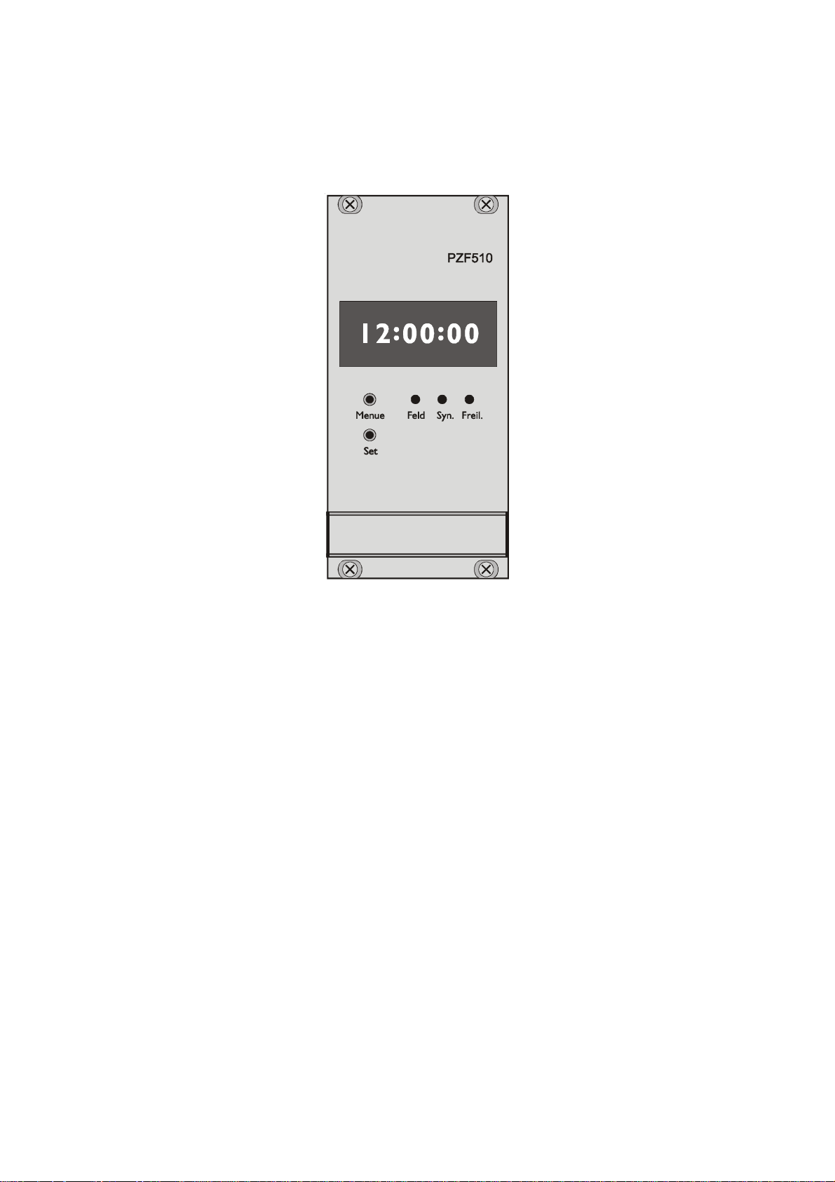
Front panel
Pilot lamps
The 'Feld'-LED is switched on if a DCF-signal with at least minimum field strength
needed for the correlation receiption is detected at the input of the receiver.
The 'Syn.'-LED indicates that the autocorrelation coefficient decreases beyond 52%
and correct receiption is not possible therefore. This happens if a strong interferer
within the bandwidth of the receiver is present or the transmitter is switched of.
If the 'Freil.'-LED is on, it was not possible to synchronize the internal realtime
clock to DCF-time. This condition occures for at most two minutes after switching on
the PZF510, because two DCF-telegrams are checked for plausibility before the data is
taken over. Short disturbance of receiption can cause this state too.
8
Page 9

Display
The eight digit alphanumeric display shows important information concerning status and
time. The setting of system parameters is also done with the help of the display.
Control keys
It is possible to change the displayed information (time, date or status information) by
two keys. The 'Menu'-key selects one of several menus. After presing the 'Set'-button
the belonging information appears on the display. Furthermore, the keys are used to
set user-specific parameters in several submenus.
Menu items
The type of DCF-clock and the software revision are displyed first after power-up.
The following informations are readable before the PZF510 switches to time-display
automatically:
PZF REC.
REV:x.xx
The handling of any queries will be simplified if the software revision is given by
the user.
The following menus are available then:
TIME:
The current time is displayed.
DATE:
The actual date appears on the display.
DAY o.W.
The day of week will be displayed
9
Page 10

PZF STAT
Informations about the decoding of the pseudo-random sequence are available in this
menu. The following texts may be displayed:
GSYNC
The pseudo-random sequence is read into the internal RAM for one second and the
system tries to achieve a coarse synchronisation. This procedure starts after power-up
or worse receiption for more than ten seconds.
K: xx%
If the coarse synchronisation was successfull, the receiver enters the state of finecorrelation. The system tries to lock the received PZF as exact as possible to generate
a precise time frame. The display shows the correlation coefficient at the end of each
second, which can be in the range of 52% to 77%. A high value for the coefficient
should be achieved by choosing a suitable position for the antenna.
The essential part of the tracking is completed five seconds after the appearence of
'K:xx%' and the generation of pulses per minute and per second starts. Tracking steps
of three microseconds are possible each second until the internal realtime clock is
synchronized (two minutes max.). Afterwards, corrections of the time frame are
executed per minute only. The direction of these steps is displayed by the characters '>'
or '<' behind the digits of the correlation coefficient.
FIELD
The digitized value of the field strength is displayed in this menu. There is a logarithmic relation between this value and the field strength. This menu is useful for
mounting the antenna, like described in chapter 'Assembly of antenna'.
SETUP
The user-specific parameters of the PZF510 are set in this menu. To avoid the erroneous
change of these parameters, it is not possible to enter the submenus by a simple pressing
of the 'Set'-key. The first submenu is entered if the 'Set'-button is pressed until the
character '*' is displayed behind the text 'SETUP' and the 'Menu'-key is actuated then.
The following submenus are selectable ('Set'-button and 'Menu'-key used as usual now):
10
Page 11

DIST.o.T
The distance to the transmitter is entered in this menu for compensating the propagation delay of the received pseudo-random code. This setting should be done as exact as
possible because the absolute precision of the time frame is influenced by this value.
After pressing the 'Set'-button a four digit kilometer-value is displayed. By pressing
the 'Set'-key again, the first position is selected (flashing digit). To choose a different
digit, the 'Menu'-key has to be pressed, to increment the current digit the 'Set'-button
must be used. If the value is entered, it will be stored by pressing the 'Menu'-key until
the display returns to the setup submenu. The km-value is stored in the internal
EEPROM of the board.
SYNTH.
The output frequency of the internal synthesizer is selected in this menu. This can be
done in the range of 1/3Hz to 9.999MHz.
After setting the frequency (the buttons are used the same way as for setting the kmvalue) it will be stored in the battery-backed RAM of the PZF510. This value is
available directly after a reset therefore.
SYNTH M.
This menu configueres at which time after power-up the frequency generation of the
synthesizer starts. The following settings are possible:
allways
Frequency-generation immediately after reset.
aft. SYN
The clock has to synchronize first before the frequency-generation starts. Frequencies
less than 10kHz are phase locked to the precise pulse per second at once.
TIME REF
The selection of timezone MEZ/MESZ or UTC can be done in this menu.
PAR.COM0
Framing and baud rate of the serial channel COM0 are set in this submenu. The
following parameters are possible:
Baud rate: 600, 1200, 2400, 4800, 9600 Baud
Framing: 7O2, 7N2, 7E1, 7E2, 8N1, 8N2, 8E1
11
Page 12

PAR. COM1
The parameter values of serial channel COM1 are selected in this submenu.These
settings are totally independant of COM0, the values allowed are the same as before:
Baud rate: 600, 1200, 2400, 4800, 9600 Baud
Framing: 7O2, 7N2, 7E1, 7E2, 8N1, 8N2, 8E1
SER.MODE
The mode of operation of the serial ports is selected in this submenu. After pressing
the 'Set'-buttton this text is displayed:
0 : x 1 : x
The following settings can be made for each COM-port instead of the 'x' behind the
colons:
'S' Time telegram per second
'M' Telegram per minute
'R' Telegram on request (after sending an ASCII '?', 3F hex)
OSZ.ADJ.
The basic model of the PZF510 includes a voltage controlled temperature compensated
oszillator (VCTCXO, VCOCXO optional). Its nominal frequency of 10MHz is adjusted
by using two digital-to-analog converters (DACs). One of them is responsible for the
coarse tuning and the other one for the fine adjustment of the oszillator. The value for the
coarse-DAC is settable in the range of 0 to 4095 in this menu.
This value should only be changed by specialized personnel of company Meinberg and not by the user!
DAC CLR
The value of the fine DAC is displayed in this submenu. If the 'Set'-button is pressed
for approximately two seconds, the DAC is set to its mid-scale value and the difference to its last value is added to the coarse DAC proportional.
This process is released automatically if the value of the fine DAC exceeds its
limits (0...4095). Therefore the setting of the value to mid-scale by hand is
reserved for service purposes only.
SER. No.
The eight digit serial number of the PZF510 is displayed. If there is any malfunction of
the clock this number may be helpful to eliminate possible defects.
12
Page 13

Asynchronous serial interfaces
Two independant serial interfaces (RS232) are available at the rear connector of the
clock PZF510. As set in menu 'Ser. Mode', the serial ports can send the Meinberg
standard time string either per second, per minute or on request. Additional menus are
used to set the framing and baudrate of these interfaces. The time string is build of 32
ASCII characters and inlcudes information about time, date and status. The structure
of the string is described in chapter 'Format of the Meinberg stantard string'.
Pulse outputs
TTL-low and TTL-high active pulses per minute and per second are generated by the
PZF510, which are available at the VG-connector.
Because the internal time frame of the clock has not yet been synchronized with the
pseudo random sequence, no pulses are generated directly after reset. In case of
normal receiption, the receiver needs about 12 seconds for coarse and another 5
seconds for fine synchronization. So, pulses are generated approximately 17 seconds
after reset.
Standard frequencies
The PZF510 delivers six standard frequencies. The outputs 100kHz, 1MHz and 10MHz
are derived from the main oszillator of the clock which is phase locked to the DCFsystem by a digital PLL (phase locked loop). The temperature-dependant drift and the
aging of the oszillator can be compensated by this procedure. Therefore the excellent
short-term stability of the standard frequencies of +/- 5·10
TCXO) is achieved. The value for regulating the digital-to-analog converter of the PLL
is avilable directly after reset because it is stored in the battery-backed RAM of the clock.
If the DCF-transmitter fails, the oszillator is controled by this value also. The accuracy of
the standard frequencies will not be worse than 1·10
-8
therefore.
The outputs 77.5kHz, 155kHz and 310kHz are locked to the receiver-PLL directly.
They are derived from a DDS-circuit (DDS: direct digital synthesis) which causes a
high phase jitter compared to the other standard frequencies. These outputs should
only be used as standard frequencies if the receiver is synchronous with DCF77.
-9
(standard version with
for one hour without receition
13
Page 14

Frequency synthesizer
The synthesizer of the PZF510 generates a frequency in the range of 1/3Hz to
9.999MHz, which can be set in the menu 'SYNTH.'. The synthesizer-output is available with TTL-level, as a sinewave signal or an open drain output at the VG-connector.
The frequency to be generated can be adjusted by giving the four digits of highestorder, lower significant digits are set to zero. Only the fractions xxx.3Hz, xxx.5Hz and
xxx.6Hz are allowed in the Hertz-range. Frequencies of xxx.3Hz or xxx.6Hz lead to a
periodic fraction, that means to correct 1/3Hz or 1/6Hz, often used by ripple control
systems.
Up to a value of 10kHz the synthesizer is phase-locked to the pulse per second. The
accuracy of this frequency reaches the exactness of the standard frequencies therefore.
Higher frequencies than 10kHz have a maximum error of +/- 2,35 mHz.
The behaviour of the synthesizer after power-up is selectable (see menu 'SYNTH.
M'). Frequency generation can start either directly after reset or after synchronization.
DCF77 emulation
The correlation receiver PZF510 generates TTL level time marks (active High) which
are compatible with the time marks spread by the German long wave transmitter
DCF77. This long wave transmitter installed in Mainflingen near Frankfurt/Germany
transmits the reference time of the Federal Republic of Germany: time of day, date of
month and day of week in BCD coded second pulses. Once every minute the complete
time information is transmitted. The PZF510 generates time marks representing always
the DCF-time including announcement of changes in daylight saving and announcement
of leap seconds, changing the timezone in the setup menu has no effect on the generation.
The coding sheme is given below:
M Start of Minute (0)
R RF Transmission via secondary antenna (0)
A1 Announcement of a change in daylight saving
Z1, Z2 Time zone identification
Z1,Z2 = 0,1: Daylight saving disabled
Z1,Z2 = 1,0: Daylight saving enabled
A2 Announcement of a leap second
S Start of time code information (1)
P1, P2, P3 Even parity bits
14
Page 15

Time marks start at the beginning of new second. If a binary "0" is to be transmitted, the
length of the corresponding time mark is 100 msec, if a binary "1" is transmitted, the time
mark has a length of 200 msec. The information on the current date and time as well as
some parity and status bits can be decoded from the time marks of the 15th up to the 58th
second every minute. The absence of any time mark at the 59th second of a minute
signals that a new minute will begin with the next time mark. The DCF emulation output
is enabled immediately after power-up.
Realtime clock
The PZF510 includes a battery-backed realtime clock which runs crystal-precise in case
of power failure. A relativ accurate time is present immediately after power-up this way.
An additional RAM of the realtime clock is used to store important system parameters.
TIME_SYN output
This output is set to TTL-high if the receiver is in synchronous state (LED 'Freil'
switched off). The output level changes to TTL-low if the receiver is in asynchronous
state for more than one hour. The TIME_SYN output is available at the VG-connector
and can be used to release an alarm, for example.
Expansion capabilities
The signals '/RESET in/out', 'SCL out', 'SDA in/out' and 'SCL_EN' at the VGconnector are reserved for future expansions. Like the 'reserved' pins, they should not
be connected to any signal by the user.
15
Page 16

Firmware updates
Whenever the on-board software must be upgraded or modified, the new firmware can
be downloaded to the internal flash memory via the serial port COM0. There is no
need to remove the board to insert a new EPROM.
If the 'Menu' key on the front panel is pressed or the pin '/BOOT' at the bladeconnector strip is held at TTL-low level while the system is powered up, a bootstraploader is actived and waits for instructions from the serial port COM0. The new
firmware can be sent to PZF510 from any standard PC with serial interface. A loader
program will be shipped together with the file containing the image of the new
firmware.
The contents of the program memory will not be modified until the loader program
has sent the command to erase the flash memory. So if the 'Menu' key is pressed
unintentionally while the system is powered up, the firmware will not be changed
accidentially. After the next power-up, the system will be ready to operate again.
Replacing the lithium battery
The life time of the lithium battery on the board is at least 10 years. If the need arises
to replace the battery, the following should be noted:
ATTENTION!
Danger of explosion in case of inadequate replacement of
the lithium battery. Only identical batteries or batteries
recommended by the manufactur er must be used for
replacement. The waste battery must be disposed as pro-
posed by the man ufacturer of the battery.
CE label
This device conforms to the directive 89/336/EWG on the approximation of the laws of the Member States of the European Community relating to electromagnetc compatibility.
16
Page 17

PZF510 with OCXO
The optional deliverable OCXO of the PZF510 operates with a single +5V power
supply. This voltage should be sourced by a stable supply to avoid drifting of the
frequency caused by the power supply. Because of the low heating time of the
oszillator, the OCXO can be regulated to the specified precision approximately 10
seconds after power-up. During operation the OCXO-version behaves like the TCXOtype but with better accuracy.
ACCURACY: +/- 1·10-9 short term stability for standard frequencies and
synthesizer (up to 10kHz)
+/- 2·10
-8
per day without receiption of DCF77
17
Page 18

Technical specifications
RECEIVER: Direct conversion quadrature receiver with automatic gain control
Bandwidth: approx. 20Hz, external ferrite antenna
CONTROL OF
RECEPTION: The DCF-signal is checked for minimum field strength by micro-
processor. The result is indicated by LED.
In addition, the value of the digitized field strength is displayed
in menu 'FIELD'.
BATTERYBACKUP: In case of power failure an internal realtime clock runs crystal-
precise. Important parameters are stored in the system-RAM.
Life time of lithium battery: 10 years minimum
Option: capacitance-backup for about 150 hours
DISPLAY: Eight-digit alphanumeric display shows important time and
status information. Digit-height 5mm.
INTERFACES: Two independant asynchronous serial ports (RS232)
BAUD RATES: 600, 1200, 2400, 4800 oder 9600 Baud
FRAMING: 7O2, 7N2, 7E1, 7E2, 8N1, 8N2 oder 8E1
PULSE
OUTPUTS: Active-high and active-low pulses per minute and per second,
TTL-level, pulse duration 200ms
ACCURACY
OF PULSES: Time delay of two systems PZF510 with a maximum distance of
50km: typ. 20µs, max. 50µs
Time shifting of successive pulses: max. 1.5µs
PROPAGATION-
TIME
COMPENSATION:The signal delay is compensated if the distance of the receiver to
the transmitter is given.
STANDARD
FREQUENCIES: 100 kHz, 1 MHz and 10 MHz are synchronized to DCF by a
digital PLL.
Accuracy in synchronized state: +/- 5·10
Accuracy in unsynchronized state: 1·10
-9
(short term stability)
-8
for one hour
77.5 kHz, 155 kHz und 310 kHz derived from receiver-PLL
Accuracy in synchronous state: +/- 5·10-7 (short term stability)
18
Page 19

SYNTHESIZER: Frequency range: 1/3 Hz...9.999 MHz
Accuracy : up to 10 kHz see standard frequencies
> 10 kHz : +/- 2,35 mHz max.
Phase jitter : max. 60ns
SYNTHESIZEROUTPUTS: F_SYNTH: TTL-level
F_SYNTH_OD: Open Drain
Max. drain-source-voltage: 100 V
Max. drain-current: 100 mA
Dissipation power, 25° C: < 360 mW
F_SYNTH_SIN: Sinewave
Output voltage: 1.5 V eff.
Output impedance: 200 Ohm
TIME_SYN
OUTPUT: TTL-level, logical-high if receiver is synchronous
TERMINAL
CONNECTION: Blade-connector strip VG64, DIN 41612
Sub-miniatur coaxial HF-connector (SMB)
BOARD
DIMENSIONS: Eurocard size 100mm x 160mm, Epoxy 1,5mm
Front panel 12TE (61mm)
ANTENNA: Ferrite antenna in plastic housing
HUMIDITY: Relativ humidity 85% max.
TEMPERATURE
RANGE: 0° - 60° Celsius
POWER
SUPPLY: + 5V, @ 330mA.
the current below is to add when equipped with OCXO option:
< 250mA, heating time
50mA, normal operation (-40°C)
20mA, normal operation (+25°C)
10mA, normal operation (+60°C)
19
Page 20

20
Page 21

Format of the Meinberg Standard Time String
The Meinberg Standard Time String is a sequence of 32 ASCII characters starting with
the STX (start-of-text) character and ending with the ETX (end-of-text) character. The
format is:
<STX>D:dd.mm.yy;T:w;U:hh.mm.ss;uvxy<ETX>
The letters printed in italics are replaced by ASCII numbers whereas the other characters
are part of the time string. The groups of characters as defined below:
<STX> Start-Of-Text (ASCII code 02h)
dd.mm.yy the current date:
dd day of month (01..31)
mm month (01..12)
yy year of the century (00..99)
w the day of the week (1..7, 1 = Monday)
hh.mm.ss the current time:
hh hours (00..23)
mm minutes (00..59)
ss seconds (00..59, or 60 while leap second)
uv clock status characters (depending on clock type):
u: ‘#’ GPS: clock is running free (without exact synchr.)
PZF: time frame not synchronized
DCF77: clock has not synchronized after reset
‘ ‘ (space, 20h)
GPS: clock is synchronous (base accuracy is reached)
PZF: time frame is synchronized
DCF77: clock has synchronized after reset
v: ‘*’ GPS: receiver has not checked its position
PZF/DCF77: clock currently runs on XTAL
‘ ‘ (space, 20h)
GPS: receiver has determined its position
PZF/DCF77: clock is syncronized with transmitter
x time zone indicator:
‘U’ UTC Universal Time Coordinated, formerly GMT
‘ ‘ MEZ European Standard Time, daylight saving disabled
‘S’ MESZ European Summertime, daylight saving enabled
y anouncement of discontinuity of time, enabled during last hour
before discontinuity comes in effect:
‘! ’ announcement of start or end of daylight saving time
‘A’ announcement of leap second insertion
‘ ‘ (space, 20h) nothing announced
<ETX> End-Of-Text (ASCII code 03h)
21
Page 22

Signal description PZF510
Name Pin Function
GND 32a+c Reference potential
VCC in (+5V) 1a+c +5V power supply
VDD in (+12V) 2a+c +12V power supply, reserved
DCF_MARk out 4c DCF77 emulation, TTL, active high
pulse duration: 100ms or 200ms
P_SEC out 6c Pulse per second, TTL-level, active high
/P_SEC out 6a Pulse per second, TTL-level, active low
P_MIN out 8c Pulse per minute, TTL-level, active high
/P_MIN out 8a Pulse per minute, TTL-level, active low
77,5kHz out 10c 77.5kHz frequency output, TTL-level
155kHz out 11c 155kHz frequency output, TTL-level
310kHz out 12c 310kHz frequency output, TTL-level
100 kHz out 10a 100kHz frequency output, TTL-level
1 MHz out 11a 1MHz frequency output, TTL-level
10 MHz out 12a 10MHz frequency output, TTL-level
F_SYNTH out 21c Synthesizer frequency, TTL-level
F_SYNTH_OD out 22c Synthesizer frequency, open-drain
F_SYNTH_SIN out 23c Synthesizer frequency, sinewave
COM0 TxD out 26c COM0 RS-232 output
COM0 RxD in 30c COM0 RS-232 input
COM1 TxD out 24c COM1 RS-232 output
COM1 RxD in 29c COM1 RS-232 input
/BOOT in 4a Input for activating the bootstrap-loader
TIME_SYN out 19c Status output, TTL-level, high if synchronous
/RESET in/out 9c RESET-pin, reserved for expansions
Do not connect
SDA, SCL, SCL_EN Serial bus for expansions, do not connect
Reserved Reserved for future expansions, do not connect
22
Page 23

Pin assignment PZF510
1)V5+(niCCV)V5+(niCCV
2)V21+(niDDV)V21+(niDDV
3
4niTOOB/tuoKRAM_FCD
5devreser
6tuoCES_P/tuoCES_P
7
8tuoNIM_P/tuoNIM_P
9tuo/niTESER/
01tuozHk001tuozHk5,77
11tuozHM1tuozHk551
ac
21tuozHM01tuozHk013
31LCS
41NE_LCS
51ADS
61
71devreser
81
91tuoNYS_EMIT
02
12tuoHTNYS_F
22tuoDO_HTNYS_F
32tuoNIS_HTNYS_F
42tuoDxT1MOC
52
62tuoDxT0MOC
72devreser
82devreser
92niDxR1MOC
03niDxR0MOC
13
23DNGDNG
23
Page 24

24
Page 25

Structure of menus PZF510
SET
MENU
SET MENU
25
Page 26

PZF510- PZF510- E- 13. 0 1. 05
 Loading...