

Page 1

FUNKUHREN
Technical Information
Operating Instructions
NUC80E
Page 2

Impressum
Werner Meinberg
Auf der Landwehr 22
D-31812 Bad Pyrmont
Telefon: 0 52 81 / 9309-0
Telefax: 0 52 81 / 9309-30
Internet: http://www.meinberg.de
Email: info@meinberg.de
März 19, 2004
Page 3

Table of Contents
Impressum ............................................................................................ 2
Slave Line Booster NUC80E ............................................................... 5
NUC80E Features ................................................................................ 6
Installation............................................................................................ 6
Keys......................................................................................................6
The Menus in Detail............................................................................. 7
"Uhr"........................................................................................... 7
"Uhr SET"...................................................................................7
"Minuten"....................................................................................7
"Hauptuhr" .................................................................................. 7
Alarm Menus........................................................................................ 7
Technical Specifications ...................................................................... 8
CE Label ..................................................................................... 8
Schematic Line Booster............................................................ 11
Schematic Microprocessor and Display ................................... 13
Component Layout ................................................................... 15
Component Layout Display...................................................... 17
Rear Connector Pin Assignment...............................................19
Page 4

Page 5
Slave Line Booster NUC80E
NUC80E is a module to control and drive slave clocks. It needs the serial timestring of
a preconnected radio clock via the serial interface. The outputs are able to drive a line
of up to 80 slave clocks with bipolar minute and second pulses. It is possible to
cascade several NUC80E to get a number of slave lines.
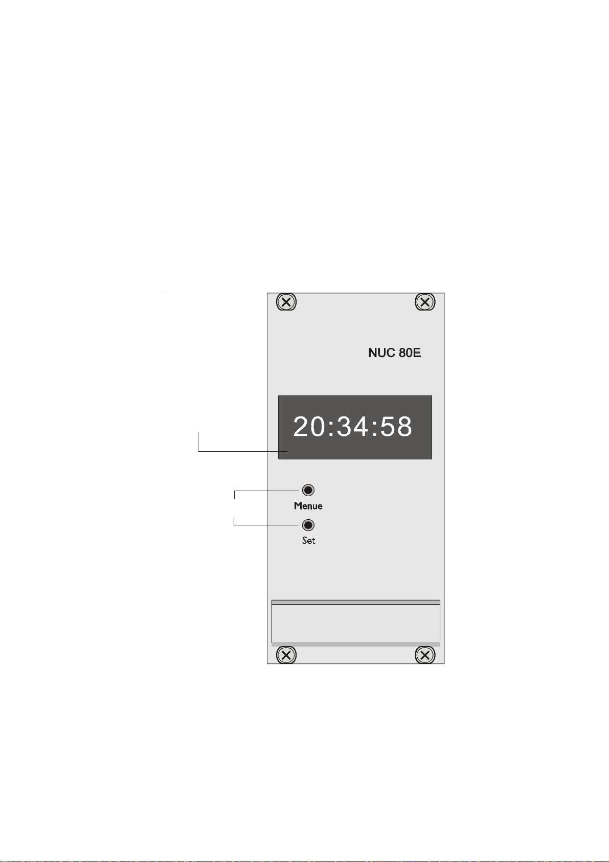
An alphanumeric LED display is used to show the time and the state of operation.
Two keys are used to control and configure the unit. The actual slave clock time is
stored secondly in a buffered RAM so that the slave clocks are able to catch up the
time after a power-fail.
alphanumeric Display
Keys
Front Panel
5
Page 6

NUC80E Features
* microprocessor system for display, setting and output-check
* 8-digit alphanumeric display
* menu-driven configuration
* short circuit proofed line booster for minute and second lines
* integrated power supply, also for preconnected radio clock (+5V)
* buffered RAM
* optocoupler for line-control
* serial current loop interface
Installation
The passive serial current loop input of the NUC80E has to be connected to an active
serial output of a radio clock. This radio clock must send the "Meinberg Standard
Time String" once per second. NUC80E compares the time string from the serial port
with the time of the slave clocks and generates the necessary pulses on the slave clock
lines. If the slave time is behind the master time it will be catched up by generating
additional pulses on the minute line every two seconds. If the slave time is ahead the
NUC80E stops generating pulses until the master time has reached the slave time. The
fetched out pulses are checked on the board. If one of the lines is shorten, the lost
pulses are generated later after the failure has been removed.
Keys
Information on time and configuration can be retrieved by the two keys in the front
panel.The Menue key lets the user choose between several menus. Pressing Set lets
the user enter the corresponding menu.
6
Page 7

The Menus in Detail
"Uhr"
This menu when selected displays the time of the slave line. After power on this menu
is shown as default.
"Uhr SET"
This menu lets the user set the internal slave clock time to the time shown on the
connected slave clocks.
When pressing SET the first time the slave line time appears on the display with the
first digit of the hours blinking. Pressing SET once more causes the slave line time to
stop. Keeping the SET key pressed for a longer time the blinking digit is incremented.
Pressing SET briefly causes the next digit to blink. Leaving this menu lets the
NUC80E start the slave line.
"Minuten"
This menu is given for testing the minute slave line. Minutes and hours are displayed.
Pressing SET lets the user switch on or off the slave line. This state is indicated with a
"H" (hold) or a "R" (run) shown in the display.
"Hauptuhr"
This menu displays the time received from the preconnected radio clock.
Alarm Menus
"UHRALARM" (blinking) indicates an invalid slave clock time. This alarm is
possible only after power up (when the buffered RAM is cleared because of empty or
defect buffer capacitor).
"MIN-FEHL" or "SEK_FEHL" (blinking) indicates a short circuit at the corresponding slave line.
"SER_FEHL" (blinking) indicates a missing or faulty serial string.
Each of this cases causes a relay to become active 90 seconds after the alarm has been
established.
7
Page 8

Technical Specifications
Display: 8-digit dot matrix display (5mm)
Interface: 20mA current loop input (passive)
Baudrate: 9600 baud
Framing: 7E2
Pulse Outputs: shorted slave line detection and autotracking of the slave clocks
potential separation between power and control parts
pulse voltage: 24V
pulse current: 0.6A max.
pulse width: 1s (minute slave line), 0.5s (second slave line)
pulse outputs short circuit proof
Alarm Output: Active when slave line is shortened or in case of driving failure
Connector: Male connector, mixed F/H, DIN 41612
Type F: 24 poles, type H: 7 poles
Power
Requirements: Input: 230V/50Hz
Output: +5V/350mA (power supply for fhe radio clock)
Physical
Dimensions: Eurocard, 100mm x 160mm, 1.5mm Epoxy
Front Panel: Anodized aluminium, 60 mm wide
Ambient
Temperature: 0 ... 50°C
Humidity: max. 85 %
CE Label
This device conforms to the directi ve 89/336/EWG on the
approximation of the laws of the Member States of the European
Community relating to electromagnetc compatibility .
8
Page 9

The wiring is explained in the following drawing. The connection of the slave clocks
occurs via the rear VG connector. The correct polarity of the connected slave clocks
can be checked by comparing the NUC80E slave line time with the time displayed on
the slave clocks. If the slave clocks are one second/minute past or ahead the corresponding line must be connected to the NUC80E with reverse polarity.
9
Page 10

10
Page 11

Schematic Line Booster
11
Page 12

12
Page 13

Schematic Microprocessor and Display
13
Page 14

14
Page 15

Component Layout
15
Page 16

16
Page 17

Component Layout Display
17
Page 18

18
Page 19

Rear Connector Pin Assignment
zbd
2)V5+(niCCV)V5+(niCCV)V5+(niCCV
4tuoneve.niMtuoddo.niM
6tuoneve.ceStuoddo.ceS
8
01
21mralAniAm02-niAm02+
41DNGDNGDNG
61
02
22
42
62
82)1L(CAV032
03 )N(CAV032
23EP
Male connector, mixed F/H, DIN 41612
Type F: 24 poles, type H: 7 poles
19
Page 20

 Loading...