

Page 1

FUNKUHREN
Technical Information
Operating Instructions
HSC509
Page 2

Impressum
Werner Meinberg
Auf der Landwehr 22
D-31812 Bad Pyrmont
Phone: ++49 52 81 - 9309-0
Fax: ++49 52 81 - 9309-30
Internet: http://www.meinberg.de
Email: info@meinberg.de
June 25, 2004
Page 3

Table of Contents
Impressum ............................................................................................ 2
General Information about DCF77 ...................................................... 7
HSC509 ................................................................................................ 8
HSC509 Features ................................................................................. 8
LF Receiver ................................................................................ 9
Microprocessor System .............................................................. 9
LC Display.................................................................................. 9
Buffered Real Time Clock.......................................................... 9
Slave Clocck Pulses.................................................................... 9
Relay Outputs ........................................................................... 10
Serial Interfaces ........................................................................ 10
Outputs ............................................................................ 10
Inputs............................................................................... 10
Installation.......................................................................................... 11
Power Supply............................................................................ 11
Mounting the Antenna .............................................................. 11
Powering Up the System ..........................................................11
Operation............................................................................................ 12
MENU Key............................................................................... 12
CLR/ACK Key ......................................................................... 12
NEXT Key................................................................................ 12
INC Key.................................................................................... 12
INC Key together with CLR/ACK Key ................................... 12
Page 4

The Menus in Detail........................................................................... 13
Root Menu ................................................................................ 13
Menu Day Plan ......................................................................... 14
Programming a Plan .................................................................14
Select a Plan..............................................................................14
Select a Switching Program......................................................15
Editing Holydays................................................................................17
Cyclic Pulses ...................................................................................... 18
Table of possible Pulse Periods ................................................ 18
Configuration............................................................................ 19
Clear Data .......................................................................................... 20
Clear RAM................................................................................20
Clear Plan ................................................................................. 20
Setting the Clock Manually................................................................21
Configuration Time Zone .................................................................. 21
Slave Clock Operation .......................................................................22
Display Slave Line Time .......................................................... 22
Set Slave Line Time/Slave Clocks ...........................................23
Setup Relay State ...............................................................................23
Firmware Updates .............................................................................. 24
Inquiring Serial Number and Software Revision............................... 24
Technical Specifications HSC509 ..................................................... 25
Rear Panel Connectors..............................................................25
CE Label ................................................................................... 25
Pin Assignment of the Phoenix MCD Connector.....................26
Page 5

Technical Specifications ....................................................................27
Format of the Meinberg Standard Time String ........................ 29
Component Layout Main Board ............................................... 31
Component Layout Display Board ........................................... 33
Menu Quick Reference ...................................................................... 35
Page 6

Page 7

General Information about DCF77
The radio remote clocks made by Meinberg receive the signal from the long wave
transmitter DCF77. This long wave transmitter installed in Mainflingen near Frankfurt/Germany transmits the reference time of the Federal Republic of Germany. This
time reference is either the Central European Time (Mitteleuropäische Zeit, MEZ) or
the Central European Summer Time (Mitteleuropäische Sommerzeit, MESZ). The
transmitter is controlled by the atomic clock plant at the Federal Physical Technical
Institute (PTB) in Braunschweig/Germany and transmits the current time of day, date
of month and day of week in coded second pulses. Once every minute the complete
time information is available.
At the beginning of every second the amplitude of the high precision 77.5 kHz
carrier frequency is lowered by 75% for a period of 0.1 or 0.2 sec. The length of these
time marks represent a binary coding scheme using the short time mark for logical
zeroes and the long time mark for logical ones. The information on the current date
and time as well as some parity and status bits can be decoded from the time marks of
the 15th up to the 58th second every minute. The absence of any time mark at the 59th
second of a minute signals that a new minute will begin with the next time mark.
Our radio remote clocks decode the highly accurate information on date and time
within a wide range around Germany. So some of our clocks are installed in Bilbao/
Spain as well as in the city of Umeå in northern Sweden - fully satisfying the
requirements of the users. The radio remote clocks automatically switch to summertime and back. The reception of the time information is free of charge and does not need
to be registered.
Generally it is important to position the antenna in an optimal way. It should be
mounted at least 30 centimeters away from the clock unit and from solid steel. The
antenna should be aligned at a right angle to the direction of the transmitter (Frankfurt).
Figure: Decoding Scheme
P
8
3
M
4
Year of the Century
Month of Year
Day of Week
Day of Month
0
0
2
0
1
0
8
4
2
1
1
0
50
8
4
2
1
4
2
1
40
0
2
0
1
8
4
2
1
0
30
2
0
P
2
0
1
Hour
P
8
1
1
4
2
(reserved)
10
R
A
1
Z
1
Z
2
20
A
2
S
1
2
4
8
1
0
2
4
0
Minute
0
M Start of Minute (0.1 s)
R RF T ransmission via secon dary antenna
A1 Announcement of a ch ange in dayligh t saving
Z1, Z2 Time zone identification
Z1, Z2 = 0, 1: Daylight saving disabled
Z1, Z2 = 1, 0: Daylight saving enabled
A2 Announcement of a lea p second
S Start of time code information
P1, P2, P3 Even parity bits
7
Page 8
HSC509
The radio remote clock HSC509 has been designed for applications where two
independent serial interfaces and up to four free programmable relay outputs are
needed. The clock also offers the possibility to control slave clocks via the integrated
slave clock drivers. The clock is equipped with an internal power supply.
HSC509
NETZ
MOD.
FLED
FREIL.
CLR/ACK NEXT INCMENU
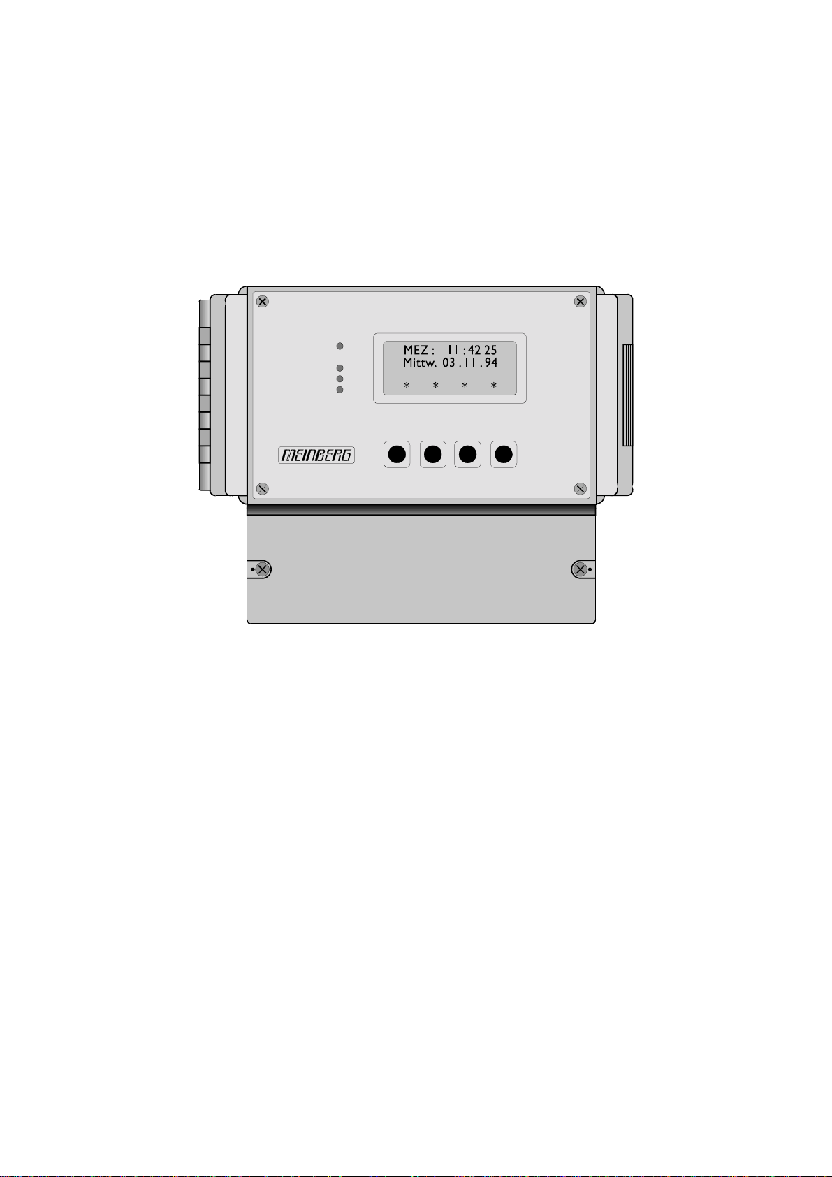
Frontview HSC509
HSC509 F eatures
The radio clock HSC509 offers a number of functions and is mounted in a plastic
housing for wall-mounting. It provides four free programmable relay outputs, a slave
clock master with two slave lines and two independent serial interfaces. The 100mm x
160mm wide frontpanel includes a 4 x 16 character LC display, four control LEDs and
four keys. The external ferrite antenna is connected to the receiver via a 50 ohm
coaxial cable. If the distance between antenna and receiver exceeds 100m an amplifier
may be necessary.
The HSC509 contains a new flash EPROM with bootstrap loader that allows the
user to upload a new firmware via the serial interface without opening the housing of
the clock.
8
Page 9

LF Receiver
An external ferrit antenna is used to receive the signal from DCF77 and supplies it to the
on-board direct conversion quadrature receiver with automatic gain control. The demodulated time marks are fed t
o the clock´s microprocessor.
Microprocessor System
The time marks from the receiver circuit are filtered and decoded by the microprocessor system. Parity and consistency checks over a period of two minutes take care for
detecting errors in the received time telegram. The checked and decoded time is
written to the on-board real time clock and spread by the interfaces. A software
watchdog lets the microprocessor recover from malfunction. A power-fail comparator
resets the microprocessor if the supply voltage drops below a specified threshold. A
flash EPROM is used as program memory which can be loaded with the firmware by
the serial interface COM0.
LC Display
The 4 x 16 character LC display is used to show the receiver´s status and let the user
edit parameters. The keys described below let the user select the desired menu. The
next chapter lists all available menus in detail. A quick reference of the available
menus and submenus can be found at the end of this document.
Buffered Real Time Clock and RAM
In case of supply voltage failure the on-board real time clock keeps the time powered
by a backup capacitor for at least 100 hours. This capacitor does not need any
maintenance. The content of the RAM is buffered also. Alternatively, the clock can be
ordered with a lithium battery which has a live time of at least 10 years guaranteed.
Slave Clocck Pulses
The radio clock generates bipolar pulses to drive slave clocks. These DC isolated
pulses are generated on a second line and on a minute line. The drivers are shortcircuit protected. A short-circuit detection ensures generating the lost pulses after the
fault has been eliminated. So the slave clocks catch up the time automatically.
9
Page 10

Relay Outputs
The HSC509 provides four relay outputs that can be applied to switching times or cyclic
pulses. Eight different plans assigned to the weekdays, sundays or holidays can be edited
by the 4 keys in the frontpanel. A plan consists of up to 64 switch-on times and 64
switch-off times. Only one plan per day can be executed.
Alternative to the switching times cyclic pulses with a settable pulse length can be
programmed. A table of possible pulses and pulse lengths is given in chapter "Cyclic
Pulses". The maximum load to be applied to the relays is 50W.
Serial Interfaces
Two independent asynchronous serial ports can be used to transmit information on
date and time to other devices. Both interfaces can be configured either as a RS232
port or as a current loop port. Baudrate, framing and mode of operation can be
configured separately for COM0 and COM1. Additionally, a time zone can be assigned to each port: The drivers can be configured individually to transmit either
standard time (MEZ/MESZ=CET/CEST), standard time with suppression of daylight
saving (always MEZ=CET), or UTC. Both serial ports can send a time string once per
second, per minute or only on request The format of the time string is described in the
section "Technical Specifications".
Outputs
Both the RS232 and the current loop output of one interface (e.g. COM0) provides the
same time string and can be connected simultaneously.
When using the port in the 20mA current loop mode the additional supply voltage
of -15V is not essential either when using only the passive outputs or a lower
interference immunity is tolerated. In the second case the negative output lines have to
be connected to GND.
Inputs
Only when using the output mode "on request" the RS232 input or the 20mA current
loop input has to be connected. It is not possible to connect both inputs.
The 20mA current loop input can be driven passive or active (see "Connector Pin
Assignment"). It is possible to drive the active input without the -15V supply voltage
by connecting the "OUT-" pin to GND.
10
Page 11

Installation
P ower Supply
The system requires an operating voltage of 230V/50Hz witch is applied via the power
supply cord at the bottom of the housing.
Mounting the Antenna
Generally it is important to position the antenna in an optimal way. The antenna
should be aligned at a right angle to the direction of the transmitter (Frankfurt). It
should be mounted at least 30 centimeters away from the clock unit and from solid
steel. A distance of several meters is recommended to all TVs or computer monitors.
The scope of supply includes an active ferrite antenna for indoor mounting (AI01)
and 5m of RG174 coaxial cable. When mounting the antenna outdoor the weather
proof Antenna AW02 is to use.
P owering Up the System
After connecting the power supply and the antenna the system is ready to operate.
Time, date and the relay conditions are displayed on the LC display (the timebase
choosen for COM0 is displayed).
The brighness of the “Feld” LED in the front panel depends on the signal strength of
the DCF77 carrier. In order to get the maximum signal, the antenna should be aligned
in two steps. First it should be turned slowly until the “Feld” LED is mostly dimmed.
Finally the antenna must be turned by 90° from this position to obtain maximum
signal. If the antenna is installed properly and the signal from DCF77 can be received
without strong distortions, the "Mod." LED starts blinking exactly once per second,
corresponding to the time marks from DCF77. If this LED flashes intermediately,
there is some electrical noise around which prevents the microprocessor from decoding the time message. So a better location for the antenna must be found. In case of
correct reception it takes up to three minutes after power-up until the clock is
synchronized and the "Freil." LED is turned off. It is turned on again to indicate the
loss of or an error in reception. Without RF signal the clock runs on XTAL with an
accuracy of 10-6. The "Freil." LED indicates three different alarm conditions by
blinking:
1. If the clock has lost reception for more than 12 hours the "Freil." LED starts blinking.
2. Short-circuit on the second-line; alarm message is displayed
3. Short-circuit on the minute-line; alarm message is displayed
The serial outputs are enabled immediately after power up. Baudrate, framing,
output mode and time zone can be configured separately by two DIL switches.
11
Page 12

Operation
HSC509
NETZ
MOD.
FLED
FREIL.
CLR/ACK NEXT INCMENU
Frontpanel HSC509
MENU Key
This key lets the user step through several display menus showing specific data.
CLR/ACK Key
This key has to be used when parameters are to be modified. When this key is pressed
the parameters that have been edited are saved in the battery buffered memory. If the
menu is left without pressing CLR/ACK all changes are discarded. If the current menu
just displays data (cursor not visible) pressing this key switches to a submenu (if
available).
NEXT Key
When editing parameters (LCD cursor is visible) this key moves the cursor to the next
digit rsp. to the next parameter to be edited.
INC Key
When editing parameters this key increments the digit or letter at the cursor position.
INC Key together with CLR/ACK Key
When pressing CLR/ACK while INC is beeing pressed the currently displayed data is
cleared and the cursor jumps to the first position.
12
Page 13

The Menus in Detail
Root Menu
The root menu is shown when the receiver has completed initialization after powerup. The first two lines of the display show the time zone (as defined in the setup
menu), the actual time and the date. The third line shows the user if one of the relay
output is applied with an impulse (I). The last line shows if an output is currently
active (*) or not (-).
* means relay on
- means relay off
I means relay applied with cyclic pulse
If the INC key is pressed from the root menu a submenu is displayed showing the
receiver´s software revision:
Pic. 2.2: Submenu 1
Pressing MENU or INC again lets the menu return to the root menu.
13
Page 14

Menu Day Plan
This menu lets the user assign a plan to a corresponding day of week. The cursor starts at
"Mo" (monday) and can be stepped to the next day by pressing NEXT.
Pic. 2.3: Menu 2
Pressing INC increases the no. of the plan (01 ... 08) while CLR/ACK saves the
edited plan to the RAM. Pressing INC and CLR/ACK clears the plan of the currently
active day.
Progr amming a Plan
A Plan is a programmed sequence of several switching times. A plan consists of up
to 64 switching programs (PRG). A switching program is a set of a switch-on time
(EIN), a switch-off time (AUS) and the corresponding relay (Rel.). Up to eight plans
can be configured and assigned to any day of the week or holyday.
To program the plans and switching programms the MENU key is to press in order
to enter menu 3. The following is displayed:
Pic. 2.4: Menu 3
Select a Plan
The no. of the plan to edit (01 ... 08) can be choosen by pressing INC while the
cursor appears at the corresponding position (PLAN).
14
Page 15

Select a Switching Program
The no. of the switching program to edit (01 ... 64) can be choosen by pressing INC
while the cursor appears at the corresponding position (PRG).
When pressing INC while CLR/ACK is already pressed the program no. is set back
to 01. After the switching program no. is selected the corresponding relay and the
switching times can be edited in the same way.
After this inputs have been done, it is important to save the switching program by
pressing CLR/ACK before the next switching program is selected. Otherwise the
edited modifikations are lost.
ATTENTION
Because the calculation of the plans is based on greater/less compa-
rations of the switching times it is necessary to sort the switching
programs of one relay in a chronological order, but not all successive
switching programs have to be programmed.
15
Page 16

1. Example: correct programming
PRG: 01 REL.:1 EIN: 08:00:00 AUS: 08:00:03
PRG: 02 REL.:1 EIN: 08:40:00 AUS: 09:45:00
PRG: 03 REL.:1 EIN: — :— :— AUS: —:— :—
.
.
PRG: 09 REL.:1 EIN: — :— :— AUS: —:— :—
PRG: 11 REL.:1 EIN: 23:12:00 AUS: 23:54:00
2. Example: correct programming
PRG: 01 REL.:1 EIN: 08:00:00 AUS: 08:00:03
PRG: 02 REL.:3 EIN: 06:40:00 AUS: 20:45:00
PRG: 03 REL.:1 EIN: 12:30:00 AUS: 12:30:03
.
.
PRG: 09 REL.:2 EIN: 11:55:00 AUS: 11:57:00
PRG: 11 REL.:4 EIN: 23:12:00 AUS: 23:54:00
PRG: 12 REL.:2 EIN: 12:00:00 AUS: —:—:—
3. Example: incorrect programming
PRG: 01 REL.:1 EIN: 08:00:00 AUS: 08:00:03
PRG: 02 REL.:3 EIN: 06:40:00 AUS: 20:45:00
PRG: 03 REL.:1 EIN: 17:30:00 AUS: 18:00:00
.
.
PRG: 09 REL.:2 EIN: 11:55:00 AUS: —:—:—
PRG: 11 REL.:4 EIN: 23:12:00 AUS: 23:54:00
PRG: 12 REL.:1 EIN: 09:30:00 AUS: 09:30:03
In the third example the execution of the program 03 should switch on the relay
no. 1 at 17:30:00. However, the following program no. 12 causes the relay to keep
switched off because the actual time is past the switch-off time (09:30:03). The
program no. 03 is never executed.
16
Page 17

Editing Holydays
It is possible to program up to 99 holydays with higher priority than a weekday. The
MENU key lets the user enter the following menu:
Pic. 2.6: Menu 4
Each of the holydays are assigned to a specified date and a plan. The date can be
entered in two different ways:
1. Variable Holydays:
Day, month and year are to be entered
e.g.: DATUM: 16.03.90
In this case the plan is executed only at the 16. of march in 1990.
2. Fixed Holydays:
Day and month are to be entered
e.g.: DATUM: 01.05.—
In this case the plan is executed at the 1. of may every year.
17
Page 18

Cyclic Pulses
Instead of switching times it is possible to assign cyclic pulses to a relay. The pulse
period is to be configured by setting a two-digit value and the unit, either seconds
(sek.), minutes (min.) or hours (std.). The allowed values for the pulse period are
given in the following table. The pulse duration can be choosen from 0.1s to 9.9s in
steps of 100ms. A pulse has always a higher priority than a switching time that is
programmed for the same relay.
Pic. 2.8: Menu 5
When choosing this menu by pressing CLR/ACK the following appears on the
display:
REL.: 1
Imp.-p.: -Impl. : --
Pic. 2.9: Menu 5
- - sek.
Example:
A cyclic pulse with a period of 3 seconds and a duration of 200ms is to program. The
relay no. 1 is to select with the keys NEXT and INC. After this is done the pulse
period is to set in the same manner: Press NEXT and then INC until the value 03
appears. Then press NEXT and then INC again until sek. appears. After that the
pulse duration is to set to 0.2 sek. in the same way. If this is done the modifikations
are to save by pressing CLR/ACK. After that the pulse output is active.
Table of possible Pulse Periods
18
Page 19

Configuration
This menu lets the user configure the serial outputs:
Pic. 3.0: Menu 6
Baudrate
The baudrate is settable for COM0 and for COM1 in the following steps: 600, 1200,
2400, 4800, 9600, 19200, 38400 and 57600. The framing is settable as follows: 7E1,
7E2, 7O2, 7N2, 8E1, 8N1 or 8N2.
Output Mode
Both of the serial ports send a time string in three different output modes. Either on
request only ("auf Anfr."; sending a '?' -ASCII-Code 3Fh- to the clock), once per
second ("sekuendl.") or once per minute ("minuetlich").
19
Page 20

Clear Data
It is possible to to clear each of the plans separate as well as the whole RAM. Press
MENU as often until the following appears in the display:
Pic. 3.1: Menu ‘Löschen’
With the NEXT key the user can change between the two options (indicated by >>)
while the CLR/ACK key is used to select one of the options.
Clear RAM
After selecting "RAM löschen" with the CLR/ACK key the user is asked to confirm
the process again by pressing CLR/ACK. ATTENTION: All plans, switching programs, cyclic pulses and other configurations will be cleared. Pressing NEXT instead
of CLR/ACK lets the clock return to the menu "Löschen" without clearing the RAM.
Clear Plan
The user can enter the menu to clear plans by pressing CLR/ACK while "Plan
löschen" is marked with >>.
Pic. 3.2: Menu ‘Löschen’
With the INC key the user can enter the concerning plan to be cleared (01-08). To
abort press MENU. To confirm press CLR/ACK, the entered plan is cleared now.
Pic. 3.3: Menu ‘Löschen Plan’
20
Page 21

Setting the Clock Manually
Setting the clock manually can be done in the menu ‘Uhr stellen’:
Pic. 3.4: Menü ‘Uhr Stellen’
After the time, date and day of week have been set the modifikation has to be
confirmed by pressing CLR/ACK. Leave the menu by pressing MENU.
Configuration Time Zone
Each of the two serial interfaces can be assigned to a time zone. The user can select
one of the following options for each interface: MEZ/MESZ, UTC or MEZ). The
front panel display always shows the time zone assigned to COM0. To confirm
modifications press CLR/ACK.
21
Page 22

Slave Clock Operation
The HSC509 generates slave clock pulses that are able to control slave clocks. These
bipolar pulses have a level of 24V.
In case of power supply failure the time is saved in a buffered memory. After restart
of the system the lost pulses are generated automatically so that the slave clocks will
be set correctly. The extra minute pulses are added every two seconds. The pulse
duration of the minute pulses is 1s, the duration of the second pulses is 0.5s.
The master clock has no feedback from the slave clocks to find out what time they
show. So if the system is turned on for the first time or slave clocks are added, the
slave clocks must be initially set to a well defined state. This can be done in the menu
‘Nebenuhr setzen’.
Pic. 3.5 Pic. 3.6
Pic. 3.5: The menu ‘SETUP Nebenuhr’ lets the user enter the submenu ‘Nebenuhrenzeit’ by pressing CLR/ACK.
Pic. 3.6: In this submenu the user can choose eiter to see the slave line time
displayed (>>anzeigen) or to set the slave line time/the slave clocks (>>setzen). The
choice is done by pressing NEXT and confirm with the CLR/ACK key.
Display Slave Line Time
The actual slave line time is displayed. There are three modes:
1.) normal mode: slave line time is synchronous with the clock's time
2.) hold mode line time > clock time; line time waits for clock time
3.) follow mode line time < clock time; line time catches up clock time
22
Page 23

Set Slave Line Time/Slave Clocks
When the menu ‘>>setzen’ is selected the slave line is stopped and no pulses are
generated until the menu is leaved.
Pic. 3.7
In the second line the user can edit the slave line time. Here the current time of the
slave clocks should be entered. After confirming with CLR/ACK the time is saved in
the RAM and the HSC509 starts generating pulses on the slave lines. The slave line
time is displayed either waiting for the clock time or trying to catch up the clock time.
It is possible to pulse the minute and the second line manually by changing ‘stop’ into
‘run’ behind the according line MIN. or SEK.. In this mode the internal slave line time
is also incremented, so it is necessary to check it again before the menu is confirmed
with the CLR/ACK key. The displayed slave line time must match exactly with the
slave clocks time. Otherwise the slave line time is to set again.
In the set-manually mode it is easy to check the right polarity of the bipolar minute
and second line pulses:
If an odd value for the slave line minute or the slave line second is displayed, the
corresponding hand of the slave clocks must move to an odd count. The even values
must behave correspondingly. If one of the slave clocks behaves contrary, it must be
connected to the master clock with reverse polarity.
Setup Relay State
In the menu ‘SETUP Schaltzustände’ it is possible to set or to clear the relays
manually regardless of the switching programs. The display shows the four relays with
the corresponding state. Using NEXT and INC lets the user switch on or off each of
the relays.
With the MENU key the user leaves this menu. The relays return to the state they
have had before entering the setup relay state menu.
23
Page 24

Firmware Updates
Whenever the on-board software must be upgraded or modified, the new firmware can
be downloaded to the internal flash memory via the serial port COM0.
If the MENU key is pressed while the system is powered up, a bootstrap-loader is
actived and waits for instructions from the serial port COM0. The new firmware can
be sent to the HSC509 from any standard PC with serial interface. A loader program
will be shipped together with the file containing the image of the new firmware.
The contents of the program memory will not be modified until the loader program
has sent the command to erase the flash memory. So if the MENU key is pressed
unintentionally while the system is powered up, the firmware will not be changed
accidentially. After the next power-up, the system will be ready to operate again.
Inquiring Serial Number and Softwar e Revision
The serial number and the revision of the loaded software can be red out by sending
the three characters "SN!" via COM0 to the clock that starts sending the following
string:
SN:HSC509 9041260 REV:01.00/01
The software revision is updated automatically with every update of the firmware. The
serial number is fixed in an I2C bus EEPROM and can not be changed.
24
Page 25

Technical Specifications HSC509
HOUSING: plastic housing for wall mounting, Bopla RegloCard-Plus 1700
Front panel aluminium (100mm high, 160mm wide)
PROTECTION
RATING: IP43
PHYSICAL
DIMENSIONS: 193mm wide x 160mm high x 131mm deep
Rear Panel Connectors
Name Type Signal Cable
ST1 32pin Phoenix MCD unshielded
Antenna BNC 77.5 kHz shielded coaxial cable
Power supply power cord receptacle 230V/50Hz power supply cord
CE Label
This device conforms to the directi ve 89/336/EWG on the
approximation of the laws of the Member States of the European
Community relating to electromagnetc compatibility .
25
Page 26

Pin Assignment of the Phoenix MCD Connector
116
Netz
230V
Fuse
T200mA Antenne
17 32
oben
unten
1 P_SEK gerade 17 TxD (COM0)
2 P_SEK ungerade 18 RxD (COM0)
3 P_MIN ge rade 19 GND
4 P_MIN ungerade 20 OUT- (COM0)
5 REL1 on 21 OUT+ (COM0)
6 REL1 off 22 VCC
7REL1 com 23IN+ (COM0)
8 REL2 on 24 IN- (COM0)
9 REL2 off 25 TxD (COM1)
10 REL2 com 26 RxD (COM1)
11 REL3 on 27 GND
12 REL3 off 28 OUT- (COM1)
13 REL3 com 29 OUT+ (COM1)
14 REL4 on 30 VCC
15 REL4 off 31 IN+ (COM1)
16 REL4 com 32 IN- (C OM1)
26
Page 27

Technical Specifications
RECEIVER: Direct conversion quadrature receiver with automatic gain control
Bandwidth: approx. 20Hz
DISPLAY: LC-Display, 4 x 16 characters
Power (Netz), modulation (Mod.), field strength (Feld) and
running on XTAL (Freil.) indicated by LEDs
TIMECODE
CHECK: multiple software check of the incoming timecode
parity and consistency check over a period of two minutes
RUNNING
ON XTAL: without RF signal the clock runs on XTAL
with an accuracy of 10
BUFFERING: In case of supply voltage failure the on-board RTC keeps the
time based on XTAL and the content of the RAM for more than
100 hours (buffer capacitor)
optional lithium backup battery (life time: 10 years)
-6
RELIABILITY
OF OPERATION: A software watchdog lets the microprocessor recover from
malfunction. A power-fail comparator resets the microprocessor if the supply voltage drops below a specified threshold.
SLAVE LINE
OUTPUTS: bipolar slave clock pulses (minute and second), DC isolated,
short circuit proofed
pulse voltage: 24V
pulse current: 0.6A max.
pulse width: 1s (minute slave line)
0.5s (second slave line)
OUTPUTS: 4 relay outputs (changeover contact); max. 50W load each
27
Page 28

INTERFACES: 2 independent interfaces (COM0 and COM1)
baudrate, framing, output mode and time zone are configurable
for each interface
COM0: 1 RS232 output, 1 RS232 input
1 active/passive current loop output
1 active/passive current loop input
COM1: 1 RS232 output, 1 RS232 input
1 active/passive current loop output
1 active/passive current loop input
TRANSMISSION
SPEED: configurable by menu
600, 1200, 2400, 4800, 9600, 19200, 38400 or 57600 baud
FRAMING: configurable by menu
7E1, 7E2, 7N2, 7O2, 8E1, 8N1 or 8N2
OUTPUT MODE : configurable by menu
once per second, once per minute, only on request ("?")
TIME ZONE: configurable by menu
MEZ/MESZ=CET/CEST, MEZ=CET, UTC
OUTPUT STRING:refer to: "Format of the Meinberg Standard Time String"
CONNECTORS: Phoenix MCD 1,5/16-G1-3,81 (32pin connector)
coaxial RF connector (BNC type)
ANTENNA: active external ferrite antenna in a plastic case
Length of the cable: up to 100m or more without amplifier
POWER
REQUIREMENTS: 230V AC, 50Hz, @100mA
HOUSING: Bopla RegloCard-Plus 1700
193mm wide x 160mm high x 131mm deep
protection rating: IP43
AMBIENT
TEMPERATURE: 0 ... 50°C
HUMIDITY: max. 85 %
OPTIONS: Hardware and software modifications accordding to customer
specification
28
Page 29

Format of the Meinberg Standard Time String
The Meinberg Standard Time String is a sequence of 32 ASCII characters starting
with the STX (start-of-text) character and ending with the ETX (end-of-text) character. The format is:
<STX>D:dd.mm.yy;T:w;U:hh.mm.ss;uvxy<ETX>
The letters printed in italics are replaced by ASCII numbers whereas the other
characters are part of the time string. The groups of characters as defined below:
<STX> Start-Of-Text (ASCII code 02h)
dd.mm.yy the current date:
dd day of month (01..31)
mm month (01..12)
yy year of the century (00..99)
w the day of the week (1..7, 1 = Monday)
hh.mm.ss the current time:
hh hours (00..23)
mm minutes (00..59)
ss seconds (00..59, or 60 while leap second)
uv clock status characters:
u: ‘#’ clock has not synchronized after reset
‘ ‘ (space, 20h) clock has synchronized after reset
v: ‘*’ DCF77 clock currently runs on XTAL
‘ ‘ (space, 20h) DCF77 clock is sync'd with transmitter
x time zone indicator:
‘U’ UTC Universal Time Coordinated, formerly GMT
‘ ‘ MEZ European Standard Time, daylight saving disabled
‘S’ MESZ European Summertime, daylight saving enabled
y anouncement of discontinuity of time, enabled during last hour
before discontinuity comes in effect:
‘!’ announcement of start or end of daylight saving time
‘A’ announcement of leap second insertion
‘ ‘ (space, 20h) nothing announced
<ETX> End-Of-Text (ASCII code 03h)
29
Page 30

30
Page 31

Component Layout Main Board
31
Page 32

32
Page 33

Component Layout Display Board
33
Page 34

34
Page 35

Menu Quick Reference
35
Page 36

 Loading...