

Page 1

Technical Information
Operating Instructions
GPS169PCI
with IRIG-Generator
Page 2

Impressum
Meinberg Funkuhren GmbH & Co. KG
Auf der Landwehr 22
D-31812 Bad Pyrmont
Phone: ++49 52 81 - 9309-0
Fax: ++49 52 81 - 9309-30
Internet: http://www.meinberg.de
Email: info@meinberg.de
February 20, 2006
Page 3

Table of Contents
Impressum ............................................................................................ 2
Driver Diskette ..................................................................................... 4
Content of the diskette .......................................................................... 5
General information .............................................................................. 6
Block diagram GPS169PCI .................................................................. 7
GPS169PCI features ............................................................................. 8
Time zone and daylight saving .................................................... 8
Asynchronous serial ports ........................................................... 9
Time capture inputs ..................................................................... 9
Pulse and frequency outputs ........................................................ 9
DCF77 emulation ...................................................................... 10
Connectors and LEDs in the rear slot cover ....................................... 11
Installing the radio clock ..................................................................... 12
Configuring the 9 pin connector ................................................ 12
Mounting the board ................................................................... 12
Mounting the antenna ................................................................ 13
Powering up the system............................................................. 13
Firmware updates ............................................................................... 14
Replacing the lithium battery .............................................................. 15
CE label .............................................................................................. 15
Timecodes .......................................................................................... 16
The timecode generator ............................................................. 16
IRIG standard format................................................................. 17
AFNOR-standard format........................................................... 18
Assignment of CF Segment in IEEE1344 mode ....................... 19
Generated timecodes ................................................................. 20
Selection of timecode ....................................................... 20
Page 4

Table of Contents (continued)
Technical Specifications GPS169PCI ................................................ 21
Assignment of the 5 pin jumper block ....................................... 23
Technical specifications of antenna ........................................... 24
Assembly with CN-UB/E (CN-UB-280DC) ............................ 25
Time strings ............................................................................... 26
Format of the Meinberg Standard time string ................... 26
Format of the Meinberg Capture String ........................... 27
Format of the SAT-time string ......................................... 28
Format of the NMEA 0183 string (RMC) ....................... 29
Format of the Uni Erlangen string (NTP) ........................ 30
Format of the ABB SPA time string ................................ 32
Driver Diskette
4
Page 5

Content of the diskette
The diskette contains a driver program that keeps the computer´s system time synchronous to the board time. If the present delivered diskette doesn’t include a driver
program for the operating system used, it can be downloaded from:
http://www.meinberg.de/english/sw/
On the diskette there is a file called „readme.txt“, which helps installing the driver
correctly. The content of this file is as follows:
Installation Instructions
-------------------------
Execute Setup.exe and choose the installation directory.
By default, the installation directory is:
C:\Program Files\Meinberg\MbgMon
Then shut down the computer, install the Meinberg radio
clock plug-in board into a free slot and reboot.
Now you are asked to install a driver. The driver file
MEINBERG.INF can be found in the subdirectory Driver\PnP
of the installation directory.
After the installation is complete, start the monitor
program MbgMon. Start the time service, control the state
of the reference clock and configure the device(s).
Copyright (C) Meinberg Funkuhren, Bad Pyrmont, Germany
5
Page 6

General information
The satellite clocks made by Meinberg have been designed to provide extremly
precise time to their users. The clocks have been developed for applications where
conventional radio clocks can´t meet the growing requirements in precision. High
precision available 24 hours a day around the whole world is the main feature of the
new system which receives its information from the satellites of the Global Positioning System.
The Global Positioning System (GPS) is a satellite-based radio-positioning, navigation, and time-transfer system. It was installed by the United States Departement
of Defense and provides two levels of accuracy: The Standard Positioning Service
(SPS) and the Precise Positioning Service (PPS). While PPS is encrypted and only
available for authorized (military) users, SPS has been made available to the general
public.
GPS is based on accurately measuring the propagation time of signals transmitted
from satellites to the user´s receiver. A nominal constellation of 24 satellites together
with some active spares in six orbital planes 20000 km over ground provides a
minimum of four satellites to be in view 24 hours a day at every point of the globe.
Four satellites need to be received simultaneously if both receiver position (x, y, z)
and receiver clock offset from GPS system time must be computed. All the satellites
are monitored by control stations which determine the exact orbit parameters as well
as the clock offset of the satellites´ on-board atomic clocks. These parameters are
uploaded to the satellites and become part of a navigation message which is retransmitted by the satellites in order to pass that information to the user´s receiver.
The high precision orbit parameters of a satellite are called ephemeris parameters
whereas a reduced precision subset of the ephemeris parameters is called a satellite´s
almanac. While ephemeris parameters must be evaluated to compute the receiver´s
position and clock offset, almanac parameters are used to check which satellites are
in view from a given receiver position at a given time. Each satellite transmits its
own set of ephemeris parameters and almanac parameters of all existing satellites.
6
Page 7
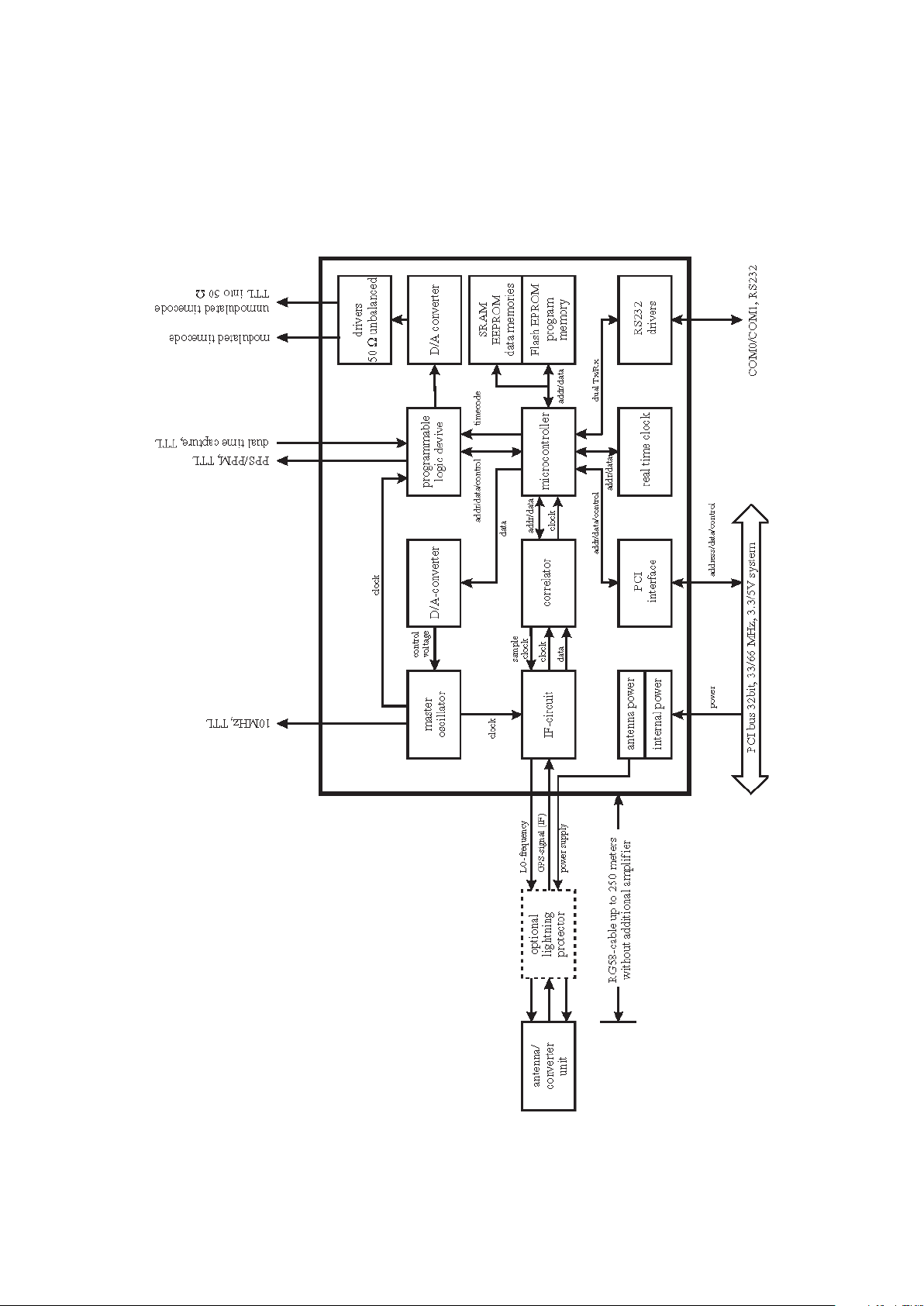
Block diagram GPS169PCI
7
Page 8

GPS169PCI features
The satellite controlled clock GPS169PCI is a plug-in board designed for computers
with 3.3V or 5V PCI bus running with clock frequencies of 33MHz or 66 MHz. The
rear slot cover integrates the antenna connector, the modulated timecode, two status
LEDs, and a 9 pin sub-D male connector.
The antenna/converter unit is connected to the receiver by a 50 Ω coaxial cable with
length up to 250m. Power is supplied to the unit DC insulated across the antenna cable.
Optionally, an overvoltage protection and an antenna distributor are available. The
antenna distributor can be used to operate up to 4 Meinberg GPS receivers using a
single antenna/converter unit.
The navigation message coming in from the satellites is decoded by satellite clock's
microprocessor in order to track the GPS system time with an accuracy of better than
250nsec. Compensation of the RF signal´s propagation delay is done by automatical
determination of the receiver´s position on the globe. A correction value computed
from the satellites´ navigation messages increases the accuracy of the board´s temperature compensated master oscillator (TCXO) to ±5•10
the TCXO´s aging. The last recent value is restored from the non-volatile memory at
power-up. Optionally, the clock is also available with a higher precision time base.
-9
and automatically compensates
A monitoring software shipped with the board can be used to check the clock's status
and configure some operational parameters.
Time zone and daylight saving
GPS system time differs from the universal time scale (UTC) by the number of leap
seconds which have been inserted into the UTC time scale after GPS has been initiated
in 1980. The current number of leap seconds is part of the navigation message supplied
by the satellites, so the satellite clock´s internal real time is based on UTC. Conversion
to local time including handling of daylight saving year by year can be done by the
receiver´s microprocessor. For Germany, the local time zone is UTC + 3600 sec for
standard time and UTC + 7200 sec if daylight saving is in effect.
The clock's microprocessor determines the times for start and end of daylight saving
time by a simple algorithm e. g. for Germany:
Start of DST is on the first Sunday after March, 25th, at 2 o'clock standard time.
End of DST is on the first Sunday after October, 25th, at 3 o'clock daylight time.
The monitoring software shipped with the board can be used to configure the time zone
and daylight savings parameters easily. Switching to daylight saving time is inhibited
if for both start and end of daylight saving the parameters are exactly the same.
The timecode (IRIG, AFNOR, IEEE) generated by GPS169PCI is available with
these settings or with UTC as reference. This can be set by the monitor program.
8
Page 9

Asynchronous serial ports
Two asynchronous serial interfaces (RS232) called COM0 and COM1 are available
to the user. Only COM0 is available at the rear panel slot cover, COM1 must use
another submin-D connector which can optionally be connected to the 5 pin jumper
block on the board. The monitoring program can be used to configure the outputs. In
the default mode of operation, the serial outputs are disabled until the receiver has
synchronized after power-up. However, they can be configured to be enabled immediately after power-up. Transmission speed, framing and mode of operation can be
configured individually for each port. Both of the ports can be configured to transmit
either time strings (once per second, once per minute, or on request with ASCII ´?´
only), or to transmit capture strings (automatically when available, or on request).
The format of the output strings is ASCII, see the technical specifications at the end
of this document for details.
Time capture inputs
The board provides two time capture inputs called User Capture 0 and 1 (CAP0 and
CAP1) which can be mapped to pins at the 9 pin connector at the rear panel. These
inputs can be used to measure asynchronous time events. A falling TTL slope at one of
these inputs lets the microprocessor save the current real time in its capture buffer.
From the buffer, an ASCII string per capture event can be transmitted via COM1 or
displayed using the monitoring program. The capture buffer can hold more than 500
events, so either a burst of events with intervals down to less than 1.5 msec can be
recorded or a continuous stream of events at a lower rate depending on the transmission speed of COM1 can be measured. The format of the output string is described in the
technical specifications at the end of this document. If the capture buffer is full a
message "** capture buffer full" is transmitted, if the interval between two captures is
too short the warning "** capture overrun" is being sent via COM1.
Pulse and frequency outputs
The satellite clock's pulse generator outputs TTL level pulses once per second
(P_SEC) and once per minute (P_MIN). A DIL switch on the board can be set up to
map one or both of the pulses to pins at the 9-pin connector at the rear slot cover.
A TTL level master frequency of 10 MHz is derived from the TCXO. By default,
this frequency is available only at the 5 pin jumper block on the board.
In the default mode of operation, the pulse outputs are disabled until the receiver has
synchronized after power-up. However, the monitoring program can be used to enable
these outputs immediately after power-up.
9
Page 10
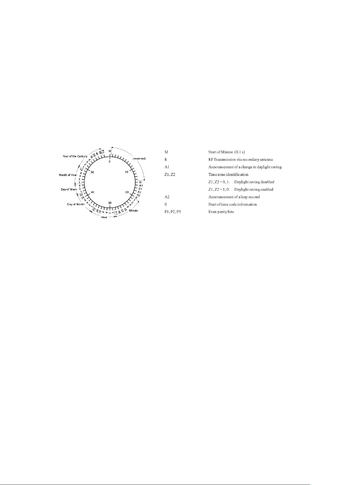
DCF77 emulation
The GPS169PCI satellite clock generates TTL level time marks (active HIGH) which
are compatible with the time marks spread by the German long wave transmitter
DCF77. This long wave transmitter installed in Mainflingen near Frankfurt/Germany
transmits the reference time of the Federal Republic of Germany: time of day, date of
month and day of week in BCD coded second pulses. Once every minute the complete
time information is transmitted. However, the clock generates time marks representing
its local time as configured by the user, including announcement of changes in daylight
saving and announcement of leap seconds. The coding sheme is given below:
Time marks start at the beginning of a new second. If a binary "0" is to be transmitted,
the length of the corresponding time mark is 100 msec, if a binary "1" is transmitted,
the time mark has a length of 200 msec. The information on the current date and time
as well as some parity and status bits can be decoded from the time marks of the 15th
up to the 58th second every minute. The absence of any time mark at the 59th second of
a minute signals that a new minute will begin with the next time mark. The DCF
emulation output is enabled immediately after power-up.
10
Page 11
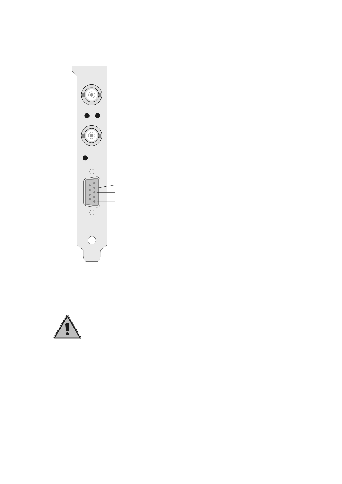
Connectors and LEDs in the rear slot cover
The coaxial antenna connector, two status
LEDs and a 9 pin sub D connector can be
found in the rear slot cover. (see figure). The
GPS
antenna
LOCK FAIL
modulated
timecode
BSL key
upper, green LED (LOCK) is turned on when
after power-up the receiver has acquired at
least four satellites and has computed its position. In normal operation the receiver position
is updated continuously as long as at least four
satellites can be received.
The lower, red LED (FAIL) is turned on
after power-up until the receiver has synchronized or if a severe error occurs during operation.
RxD
TxD
GND
A DIL switch on the board can be used to wire some TTL inputs
or outputs (0..5V) to some connector pins. In this case, absolute
care must be taken if another device is connected to the port,
because voltage levels of -12V through +12V (as commonly used
with RS-232 ports) at TTL inputs or outputs may damage the
radio clock.
The 9 pin sub D connector is wired to the
GPS169PCI's serial port COM0. Pin assignment can be seen from the figure beside. This
port can not be used as serial port for the computer. Instead, it can be uses to send out Meinberg's
standard time string to an external device.
Behind the little hole in the slot cover there is a push button (BSL) which is needed
if the clock's firmware shall be updated. See the chapture about firmware updates for
details.
11
Page 12

Installing the radio clock
Every PCI board is a plug&play board. After power-up, the computer's BIOS assigns
ressources like I/O ports and interrupt lines to the board, the user does not need to take
care of the assignments. The programs shipped with the board retrieve the settings from
the BIOS.
Configuring the 9 pin connector
By default only the signals needed for the serial port COM0 are mapped to the pins of the
connector. Whenever one of the additional signals shall be used, the signal must be
mapped to a pin by putting the appropriate lever of the DIL switch in the ON position.
The table below shows the pin assignments for the connector and the DIL switch lever
assigned to each of the signals. Care must be taken when mapping a signal to Pin 1, Pin
4 or Pin 7of the connector, because one of two different signals can be mapped to these
Pins. Only one switch may be put in the ON position in this case:
Pin 1: DIL 1 or DIL 8 ON
Pin 4: DIL 5 or DIL 10 ON
Pin 7: DIL 3 or DIL 7 ON
Those signals which do not have a lever of the DIL switch assigned are always available
at the connector:
niP-BUS-DniP-BUS-D
niP-BUS-DniP-BUS-DlangiSlangiS
niP-BUS-D
1tuoCCVV5+1
1tuoSPP232SR8
2niDxR232SR-
3tuoDxT2
4tuoMPPLTT5
4tuozHM01LTT01
5DNG--
6ni0PACLTT2
7ni1PACLTT3
7tuoCDGIRI05otniLTT Ω 7
8tuoSPPLTT4
9tuoFCDLTT6
langiSlangiSlevellangiSlevellangiS
langiS
levellangiSlevellangiShctiws-LIDhctiws-LID
levellangiS
32SR-
hctiws-LIDhctiws-LID
hctiws-LID
Mounting the board
The computer has to be turned off and its case must be opened. The satellite clock can be
installed in any PCI slot not used yet. The rear plane must be removed before the board
can be carefully plugged in. The computer´s case should be closed again and the antenna
can be connected to the coaxial plug at the clock's rear slot cover. After the computer has
been restarted, the monitor software can be run in order to check the clock's configuration.
12
Page 13

Mounting the antenna
The GPS satellites are not stationary but circle round the globe in a period of about 12
hours. They can only be received if no building is in the line-of-sight from the antenna to
the satellite, so the antenna/converter unit must be installed in a location from which as
much of the sky as possible can be seen. The best reception is given when the antenna
has a free view of 8° angular elevation above horizon. If this is not possible the antenna
should be installed with a mostly free view to the equator because of the satellite courses
which are located between latitudes of 55° North and 55° South.
If even this is not possible problems occure especially when at least four sattelites for
positioning have to be found.
The unit can be mounted using a pole with a diameter up to 60 mm. A standard coaxial
cable with 50 Ω impedance (e.g. RG58C) should be used to connect the antenna/
converter unit to the receiver. Cable thinner than RG58 should be avoided due to its
higher DC resistance and RF attenuation. When using the optional antenna diplexer the
total length of one antenna line between antenna, diplexer and receiver must not be
longer than 250 m. If a cable with less attenuation is used its length may be increased
accordingly (e.g. 500 m with RG213).
If the antenna cable was canned by the user: before powering up
the system, make sure that there is no short-circuit between the
inner and outer conductor of the antenna cable, because this
could cause a fault of GPS169PCI.
Powering up the system
After the board has been mounted and the antenna has been connected, the system is
ready to operate. About 10 seconds after power-up the receiver´s TCXO operates with
the required accuracy. If the receiver finds valid almanac and ephemeris data in its battery
buffered memory and the receiver´s position has not changed significantly since its last
operation the receiver can find out which satellites are in view now. Only a single
satellite needs to be received to synchronize and generate output pulses, so synchronization can be achieved at least one minute after power-up. After 20 minutes of operation
the TCXO has achieved its final accuracy and the generated frequencies are within the
spezified tolerances.
If the receiver position has changed by some hundred kilometers since last operation, the satellites´ real elevation and doppler might not match those values expected
by the receiver thus forcing the receiver to start scanning for satellites. This mode is
called Warm Boot because the receiver can obtain ID numbers of existing satellites
from the valid almanac. When the receiver has found four satellites in view it can
update its new position and switch to normal operation. If the almanac has been lost
because the battery had been disconnected the receiver has to scan for a satellite and
read in the current almanacs. This mode is called Cold Boot. It takes 12 minutes until
13
Page 14

the new almanac is complete and the system switches to Warm Boot mode scanning
for other satellites.
In the default mode of operation, neither pulse outputs nor the serial ports will be
enabled after power-up until synchronization has been achieved. However, it is possible
to configure some or all of those outputs to be enabled immediately after power-up. If the
system starts up in a new environment (e. g. receiver position has changed or new power
supply) it can take some minutes until the TCXO´s output frequency has been adjusted.
Up to that time accuracy of frequency drops to 10-8 reducing the accuracy of pulses to
±2µs.
Firmware updates
Whenever the on-board software must be upgraded or modified, the new firmware can
be downloaded to the internal flash memory via the radio clock's serial port COM0.
There is no need to open the computer case and insert a new EPROM.
If the button behind a hole in the rear slot cover is pressed for approximately 2
seconds, a bootstrap loader is activated and waits for instructions from the serial port
COM0. A loader program shipped together with the file containing the image of the
new firmware sends the new firmware from one of the computer's serial ports to the
clock's serial port COM0. The bootstrap loader does not depend on the contents of the
flash memory, so if the update procedure is interrupted, it can easily be repeated.
The contents of the program memory will not be modified until the loader program
has sent the command to erase the flash memory. So if the button has been pressed
accidentally, the system will be ready to operate again after the computer has been
turned off an the on again.
14
Page 15

Replacing the lithium battery
The life time of the lithium battery on the board is at least 10 years. If the need arises
to replace the battery, the following should be noted:
ATTENTION!
Danger of explosion in case of inadequate replacement of
the lithium battery. Only identical batteries or batteries
recommended by the manufacturer must be used for
replacement. The waste battery must be disposed as
proposed by the manufacturer of the battery.
CE label
15
Page 16

Timecodes
The transmission of coded timing signals began to take on widespread importance
in the early 1950´s. Especially the US missile and space programs were the forces
behind the development of these time codes, which were used for the correlation of
data. The definition of time code formats was completely arbitrary and left to the
individual ideas of each design engineer. Hundreds of different time codes were
formed, some of which were standardized by the „Inter Range Instrumantation
Group“ (IRIG) in the early 60´s.
Except these „IRIG Time Codes“ other formats, like NASA36, XR3 or 2137, are
still in use. The board GPS169PCI however generates the IRIG-B, AFNOR NFS 87500 code as well as IEEE1344 code which is an IRIG-B123 coded extended by
information for time zone, leap second and date. If desired other formats are
available.
The timecode generator
The board GPS169PCI generates modulated and unmodulated timecodes. Modulated signals are transmitting the information by varying the amplitude of a sinewave
carrier, unmodulated timecodes are transmitted by pulse duration modulation of a
DC-signal (TTL in case of GPS169PCI), see chapter „IRIG standard format“ for
details.
The sinewave carrier needed for modulated signals is generated in a digital way by
a programmable logic device on the board. The frequency of this signal is derived
from the main oscillator of GPS169PCI, which is disciplined by the GPS-system.
This leads to a sinewave carrier with high accuracy. Transmission of date is synchronized by the PPS (pulse per second) derived from the GPS-system.
The modulated timecode has an amplitude of 3Vpp (MARK) and 1Vpp (SPACE)
into 50 Ω. The number of MARK-amplitudes within ten periods of the carrier defines
the coding:
a) binary „0“ : 2 MARK-amplitudes, 8 SPACE-amplitudes
b) binary „1“ : 5 MARK-amplitudes, 5 SPACE-amplitudes
c) position-identifier : 8 MARK-amplitudes, 2 SPACE-amplitudes
The DC-signal has the following pulse durations accordingly:
a) binary „0“ : 2 msec
b) binary „1“ : 5 msec
c) position-identifier : 8 msec
16
Page 17

IRIG standard format
17
Page 18

AFNOR-standard format
18
Page 19

Assignment of CF Segment in IEEE1344 mode
.oNtiB.oNtiB
.oNtiB.oNtiBnoitangiseDnoitangiseD
.oNtiB
noitangiseDnoitangiseDnoitpircseDnoitpircseD
noitangiseD
noitpircseDnoitpircseD
n
oitpircseD
94
051dedocneDCBraeY
152dedocneDCBraeY
254dedocneDCBraeY
358dedocneDCBraeY
45orezsyawla,
5501dedocneDCBraeY
6502dedocneDCBraeY
7504dedocneDCBraeY
8508dedocneDCBraeY
956
06gnidnePdnoceSpaeL-PSLnoitresniSLerofebs95otputes
16dnoceSpaeL-SL
26gnidnePgnivaSthgilyaD-PSD
36emiTgnivaSthgilyaD-TSDemitgnivasthg
ytpme
5PreifitnedInoitisoP
PreifitnedInoitisoP
).1
revoegnahc
raeydedocneDCBfoelbbinwol
raeydedocneDCBfoelbbinhgih
nocespaeldda=0
ilyadgnirudtes
dnocespaeleteled=1,d
gnivasthgilyaderofebs95otputes
46ngiStesffOenozemiT'-'=1,'+'=0tesffoZTfongis
561dedocneyranibtesffOZT
662dedocneyranibtesffOZT
764dedocneyranibtesffOZT
8
68dedocneyranibtesffOZT
967PreifitnedInoitisoP
07ruoh5.0tesffOZTtesfforuohflahlanoitiddafites
17tiremfoerugif
27tiremfoerugifemiTMOFT
37tiremfoerugifemiTMOFT
47tiremfoerugifemiTMOFT
57YT
).1
).2
emiTMOFT
IRAP emitB-GIRI.lcnistibgnidecerpllanoytirap
sdnocespaelfonoiteledtroppustonseoderawmriftnerruc
ftesffO
!semitllataCTU
).2
.rorrekcolc
dekcolkcolc=00x0
deliafkcolc=F0x0
.purewopretfatsrifdezinorhcnyssikcolcnehw,deraelcsiMOFT
.emitCTUotemitGIRImor
slauqetesffOZTsulpemitGIRIdedocnE
detamixorppastneserpertiremfoerugifemit
edocemitdetarenegfonoitceleSretpahcees
19
Page 20

Generated timecodes
The board GPS169PCI generates modulated unmodulated (TTL into 50 Ω) timecodes, so that six different signals are available:
a) B002: 100pps, DC-signal, no carrier
BCD time of year
b) B122: 100pps, AM-sinewave signal, 1 kHz
BCD time of year
c) B003: 100pps, DC-signal, no carrier
BCD time of year, SBS time of day
d) B123: 100pps, AM-sinewave signal, 1 kHz
BCD time of year, SBS time of day
e) AFNOR: Code according to NFS-87500, 100pps, AM-sinewave signal, 1kHz
BCD time of year, complete date, SBS-Time of Day
f) IEEE1344: Code. according to IEEE1344-1995, 100pps, AM-sinewave signal, 1kHz
BCD time of year, SBS time of day,
IEEE1344 expansion for date, timezone, daylight saving and leap second
in Control Funktions Segment (CF)
see table „Assignment of CF Segment in IEEE1344 mode“
Modulated and unmodulated signals with the same coding (B002/B122 and B003/
B123) are always available simultaneously via the BNC- and the D-SUB-connector.
Selection of timecode
The selection of timecode is done by the monitor software.
The unmodulated timecode can be delivered as an active-high or active-low signal by
setting a jumper on the board GPS169PCI into the appropriate position:
20
Page 21

Technical Specifications GPS169PCI
RECEIVER: Six channel C/A code receiver with external antenna/converter
unit
ANTENNA: Antenna/converter unit with remote power supply
refer to chapter "Technical specifications of antenna"
ANTENNA
INPUT: Antenna circuit dc-insulated; dielectric strength: 1000V
Length of cable: refer to chapter "Mounting the Antenna"
TIME TO SYNCHRONIZATION: one minute with known receiver position and valid almanac
12 minutes if invalid battery buffered memory
PULSE
OUTPUTS: change of second (PPS, TTL level, valid on rising edge)
change of minute (PPM, TTL level, valid on rising edge)
ACCURACY OF
PULSES: better than ±250 nsec after synchronization and 20 minutes of
operation
better than ±2 µsec during the first 20 minutes of operation
TIME CAPTURE
INPUTS: triggered on falling TTL slope
Interval of events: 1.5msec min.
Resolution: 100ns
FREQUENCY
OUTPUTS: 10 MHz (TTL level)
STANDARD
ACCURACY OF
FREQUENCY: ±5.10
-9
21
Page 22

ACCURACY OF
FREQUENCY
OPTION OCXO: after sync. and 20 min of operation ±1
during first 20 minutes of operation ±2.10
Accuracy of quartz
one day, free-running ±2.10
one year, free-running ±5.10
Short term stability
<= 10 sec, GPS controlled ±1.10
<= 10 sec, free running ±3.10
Temperature drift
free running ±2.10
SSB phase noise
1 Hz besides carrier: -60 dBc/Hz
10 Hz besides carrier: -90 dBc/Hz
100 besides carrier: -120 dBc/Hz
1 kHz besides carrier: -130 dBc/Hz
.
10
-9
-8
-8
-7
-9
-9
-7
SYSTEM BUS
INTERFACE: universal board for 3.3V and 5V systems
32 bit, 33MHz or 66MHz PCI bus
compatible to PCI and PCI-X specifications
DATA FORMAT: Binary, byte serial
IRIG-OUTPUTS: Unbalanced AM-sinewave signal:
3Vpp (MARK), 1Vpp (SPACE) into 50 Ω
PWM-DC-signal:
TTL into 50 Ω, active-high or -low, selected by jumper
SERIAL PORTS: 2 asynchronous serial ports (RS-232)
Baud Rate: 300 up to 19200
Framing: 7N2, 7E1, 7E2, 8N1, 8N2, 8E1
default setting:
COM0: 19200, 8N1
Meinberg Standard time string, per second
COM1: 9600, 8N1
Capture string, automatically
22
Page 23

POWER
REQUIREMENTS: 5V ± 5%, @250mA
12V ± 5%, @190mA
-12V ± 5%, @10mA
delivered by PCI bus
RF CONNECTOR: female coaxial BNC-connectors for antenna and modulated
timecode
AMBIENT
TEMPERATURE: 0 ... 60°C
HUMIDITY: 85% max.
Assignment of the 5 pin jumper block
The jumper block can be used to access the 10 MHz frequency output and the serial port
COM1. Pin 5 is located near the board's bus connector:
Pin Signal
1 10 MHz out
2 GND
3 RxD1 in
4 TxD1 out
5 GND
23
Page 24

Technical specifications of antenna
ANTENNA: dielectrical patch antenna, 25 x 25mm
receive frequency: 1575.42 MHz
bandwidth: 9 MHz
CONVERTER: local oscillator to converter frequency: 10 MHz
first IF frequency: 35.4 MHz
POWER
REQUIREMENTS: 12V ... 18V, @ 100mA (provided via antenna cable)
CONNECTOR: coax type N, female
AMBIENT
TEMPERATURE: -40 ... +65°C
HOUSING: ABS plastic case for outdoor installation (IP56)
PHYSICAL
DIMENSION:
24
Page 25

Assembly with CN-UB/E (CN-UB-280DC)
25
Page 26

Time strings
Format of the Meinberg Standard time string
The Meinberg Standard time string is a sequence of 32 ASCII characters starting
with the STX (start-of-text) character and ending with the ETX (end-of-text) character. The format is:
<STX>D:dd.mm.yy;T:w;U:hh.mm.ss;uvxy<ETX>
The letters printed in italics are replaced by ASCII numbers whereas the other characters are part of the time string. The groups of characters as defined below:
<STX> Start-Of-Text (ASCII code 02h)
dd.mm.yy the current date:
dd day of month (01..31)
mm month (01..12)
yy year of the century (00..99)
w the day of the week (1..7, 1 = Monday)
hh.mm.ss the current time:
hh hours (00..23)
mm minutes (00..59)
ss seconds (00..59, or 60 while leap second)
uv clock status characters:
u: ‘#’ clock has not synchronized after reset
‘ ‘ (space, 20h) clock has synchronized after reset
v: different for DCF77 or GPS receivers:
‘*’ DCF77 clock currently runs on XTAL
GPS receiver has not checked its position
‘ ‘ (space, 20h) DCF77 clock is sync'd with transmitter
GPS receiver has determined its position
x time zone indicator:
‘U’ UTC Universal Time Coordinated, formerly GMT
‘ ‘ MEZ European Standard Time, daylight saving disabled
‘S’ MESZ European Summertime, daylight saving enabled
y anouncement of discontinuity of time, enabled during last hour
before discontinuity comes in effect:
‘!’ announcement of start or end of daylight saving time
‘A’ announcement of leap second insertion
‘ ‘ (space, 20h) nothing announced
<ETX> End-Of-Text (ASCII code 03h)
26
Page 27

Format of the Meinberg Capture String
The Meinberg Capture string is a sequence of 31 ASCII characters terminated by a
CR/LF (Carriage Return/Line Feed) combination. The format is:
CHx_tt.mm.jj_hh:mm:ss.fffffff<CR><LF>
The letters printed in italics are replaced by ASCII numbers whereas the other characters are part of the time string. The groups of characters as defined below:
x 0 or 1 corresponding on the number of the capture input
_ ASCII space 20h
dd.mm.yy the capture date:
dd day of month (01..31)
mm month (01..12)
yy year of the century (00..99)
hh:mm:ss.fffffff the capture time:
hh hours (00..23)
mm minutes (00..59)
ss seconds (00..59, or 60 while leap second)
fffffff fractions of second, 7 digits
<CR> Carriage Return, ASCII code 0Dh
<LF> Line Feed, ASCII code 0Ah
27
Page 28

Format of the SAT-time string
The SAT-time string is a sequence of 29 ASCII characters starting with the STX
(start-of-text) character and ending with the ETX (end-of-text) character. The format
is:
<STX>dd.mm.yy/w/hh.mm.ssxxxxuv<ETX>
The letters printed in italics are replaced by ASCII numbers whereas the other characters are part of the time string. The groups of characters as defined below:
<STX> Start-Of-Text (ASCII code 02h)
dd.mm.yy the current date:
dd day of month (01..31)
mm month (01..12)
yy year of the century (00..99)
w the day of the week (1..7, 1 = Monday)
hh.mm.ss the current time:
hh hours (00..23)
mm minutes (00..59)
ss seconds (00..59, or 60 while leap second)
xxxx time zone indicator:
‘UTC‘ Universal Time Coordinated, formerly GMT
‘MEZ‘ European Standard Time, daylight saving disabled
‘MESZ’ European Summertime, daylight saving enabled
u clock status characters:
‘#’ clock has not synchronized after reset
‘ ‘ (space, 20h) clock has synchronized after reset
v anouncement of discontinuity of time, enabled during last hour
before discontinuity comes in effect:
‘!’ announcement of start or end of daylight saving time
‘ ‘ (space, 20h) nothing announced
<CR> Carriage-return (ASCII code 0Dh)
<LF> Line-feed (ASCII code 0Ah)
<ETX> End-Of-Text (ASCII code 03h)
28
Page 29

Format of the NMEA 0183 string (RMC)
The NMEA string is a sequence of 65 ASCII characters starting with the ‘$’ character
and ending with the characters CR (carriage return) and LF (line-feed). The format is:
$GPRMC,hhmmss.ss,A,bbbb.bb,n,lllll.ll,e,0.0,0.0,ddmmyy,0.0,a*hh<CR><LF>
The letters printed in italics are replaced by ASCII numbers or letters whereas the other
characters are part of the time string. The groups of characters as defined below:
$ start character (ASCII-Code 24h)
hhmmss.ss the current time:
hh hours (00..23)
mm minutes (00..59)
ss seconds (00..59, or 60 while leap second)
ss fractions of seconds (1/10 ; 1/100)
A Status (A = time data valid)
(V = time data not valid)
bbbb.bb latitude of receiver position in degrees
leading signs are replaced by a space character (20h)
n latitude, the following characters are possible:
‘N’ north of equator
‘S’ south d. equator
lllll.ll longitude of receiver position in degrees
leading signs are replaced by a space character (20h)
e longitude, the following characters are possible:
‘E’ east of Greenwich
‘W’ west of Greenwich
ddmmyy the current date:
dd day of month (01..31)
mm month (01..12)
yy year of the century (00..99)
a magnetic variation
hh checksum (EXOR over all characters except ‘$’ and ‘*’)
<CR> carriage-return; ASCII-Code 0Dh
<LF> line-feed; ASCII-Code 0Ah
29
Page 30

Format of the Uni Erlangen string (NTP)
The time string Uni Erlangen (NTP) of a GPS-clock is a sequence of 68 ASCII
characters starting with the STX (start-of-text) character and ending with the ETX
(end-of-text) character. The format is:
<STX>tt.mm.jj; w; hh:mm:ss; voo:oo; acdfg i; bbb.bbbbn llll.lllle hhhhm<ETX>
The letters printed in italics are replaced by ASCII numbers whereas the other characters are part of the time string. The groups of characters as defined below:
<STX> Start-Of-Text (ASCII code 02h)
dd.mm.yy the current date:
dd day of month (01..31)
mm month (01..12)
yy year of the century (00..99)
w the day of the week (1..7, 1 = Monday)
hh.mm.ss the current time:
hh hours (00..23)
mm minutes (00..59)
ss seconds (00..59, or 60 while leap second)
v sign of the offset of local timezone related to UTC
oo:oo offset of local timezone related to UTC in hours and minutes
ac clock status characters:
a: ‘#’ clock has not synchronized after reset
‘ ‘ (space, 20h) clock has synchronized after reset
c: ‘*’ GPS receiver has not checked its position
‘ ‘ (space, 20h) GPS receiver has determined its position
d time zone indicator:
‘S’ MESZ European Summertime, daylight saving enabled
‘ ‘ MEZ European Standard Time, daylight saving disabled
f anouncement of discontinuity of time, enabled during last hour
before discontinuity comes in effect:
‘!’ announcement of start or end of daylight saving time
‘ ‘ (space, 20h) nothing announced
g anouncement of discontinuity of time, enabled during last hour
before discontinuity comes in effect:
‘A’ announcement of leap second insertion
‘ ‘ (space, 20h) nothing announced
30
Page 31

i leap second insertion
‘L’ leap second is actually inserted
(active only in 60th sec.)
‘ ‘ (space, 20h) no leap second is inserted
bbb.bbbb latitude of receiver position in degrees
leading signs are replaced by a space character (20h)
n latitude, the following characters are possible:
‘N’ north of equator
‘S’ south d. equator
llll.llll longitude of receiver position in degrees
leading signs are replaced by a space character (20h)
e longitude, the following characters are possible:
‘E’ east of Greenwich
‘W’ west of Greenwich
hhhh altitude above sea level in meters
leading signs are replaced by a space character (20h)
<ETX> End-Of-Text (ASCII-Code 03h)
31
Page 32

Format of the ABB SPA time string
The ABB SPA time string is a sequence of 32 ASCII characters starting with the
characters ">900WD" and ending with the <CR> (Carriage Return) character. The
format is:
>900WD:yy-mm-tt_hh.mm;ss.fff:cc<CR>
The letters printed in italics are replaced by ASCII numbers whereas the other characters are part of the time string. The groups of characters as defined below:
yy-mm-tt the current date:
yy year of the century (00..99)
mm month (01..12)
dd day of month (01..31)
_ Space (ASCII code 20h)
hh.mm;ss.fff the current time:
hh hours (00..23)
mm minutes (00..59)
ss seconds (00..59, or 60 while leap second)
fff milliseconds (000..999)
cc Check sum. EXCLUSIVE-OR result of the previous characters,
displayed as a HEX byte (2 ASCII characters 0..9 or A..F)
<CR> Carriage Return (ASCII code 0Dh)
32
Page 33

33
Page 34

 Loading...