

Page 1

FUNKUHREN
Technical Information
Operating Instructions
GPS167PC
Page 2

Impressum
Werner Meinberg
Auf der Landwehr 22
D-31812 Bad Pyrmont
Phone: ++49 52 81 - 9309-0
Fax: ++49 52 81 - 9309-30
Internet: http://www.meinberg.de
Email: info@meinberg.de
October 30, 2001
Page 3

Table of Contents
Impressum ............................................................................................ 2
Driver Diskette for DOS/Windows ...................................................... 4
General Information ............................................................................. 5
GPS167PC Features ............................................................................. 6
Time Zone and Daylight Saving................................................. 6
Asynchronous Serial Ports.......................................................... 7
Time Capture Inputs ................................................................... 7
Pulse and Frequency Outputs ..................................................... 7
DCF77 Emulation ....................................................................... 8
Connectors and LEDs in the Rear Slot Cover ..................................... 9
Installing the Radio Clock.................................................................... 9
Setting The Port Base Address ................................................... 9
Configuring the 9 pin Connector .............................................. 11
Mounting the Board .................................................................. 11
Mounting the Antenna .............................................................. 11
Powering Up the System .......................................................... 12
Files on the Diskette shipped with the Board .................................... 13
Support for other Operating Systems................................................. 13
Copying the distributed Software to the Hard Disk ........................... 13
Using PCPSINFO.EXE...................................................................... 14
The resident driver for DOS/Windows .............................................. 17
Controlling the Resident Driver ............................................... 18
Firmware Updates .............................................................................. 18
Replacing the Lithium Battery ........................................................... 19
CE Label ............................................................................................ 19
Page 4

Table of Contents (continued)
Technical Specifications GPS167PC ................................................. 21
Technical Specifications of Antenna ........................................ 23
Assembly with CN-UB/E (CN-UB-280DC) ............................ 24
Format of the Meinberg Standard Time String ........................ 25
Format of the Meinberg Capture String ................................... 26
Assignment of the 5 Pin Jumper Block .................................... 26
Component Layout GPS167PC ................................................ 27
Driver Diskette for DOS/Windows
4
Page 5

General Information
The satellite clocks made by Meinberg have been designed to provide extremly
precise time to their users. The clocks have been developed for applications where
conventional radio clocks can´t meet the growing requirements in precision. High
precision available 24 hours a day around the whole world is the main feature of the
new system which receives its information from the satellites of the Global Positioning System.
The Global Positioning System (GPS) is a satellite-based radio-positioning, navigation, and time-transfer system. It was installed by the United States Departement of
Defense and provides two levels of accuracy: The Standard Positioning Service (SPS)
and the Precise Positioning Service (PPS). While PPS is encrypted and only available
for authorized (military) users, SPS has been made available to the general public.
GPS is based on accurately measuring the propagation time of signals transmitted
from satellites to the user´s receiver. A nominal constellation of 24 satellites together
with some active spares in six orbital planes 20000 km over ground provides a
minimum of four satellites to be in view 24 hours a day at every point of the globe.
Four satellites need to be received simultaneously if both receiver position (x, y, z)
and receiver clock offset from GPS system time must be computed. All the satellites
are monitored by control stations which determine the exact orbit parameters as well
as the clock offset of the satellites´ on-board atomic clocks. These parameters are
uploaded to the satellites and become part of a navigation message which is retransmitted by the satellites in order to pass that information to the user´s receiver.
The high precision orbit parameters of a satellite are called ephemeris parameters
whereas a reduced precision subset of the ephemeris parameters is called a satellite´s
almanac. While ephemeris parameters must be evaluated to compute the receiver´s
position and clock offset, almanac parameters are used to check which satellites are in
view from a given receiver position at a given time. Each satellite transmits its own set
of ephemeris parameters and almanac parameters of all existing satellites.
5
Page 6

GPS167PC Features
The hardware of GPS167PC is a plug-in board designed for computers with standard
ISA bus architecture. The rear slot cover integrates the antenna connector, two status
LEDs, and a 9 pin sub-D female connector.
The antenna/converter unit is connected to the receiver by a 50 ohm coaxial cable
with length up to 200m. Power is supplied to the unit DC insulated across the antenna
cable. Optionally, an overvoltage protection and an antenna distributor are available.
The antenna distributor can be used to operate up to 4 Meinberg GPS receivers using a
single antenna/converter unit.
The navigation message coming in from the satellites is decoded by satellite clock´s
microprocessor in order to track the GPS system time with an accuracy of better than
250nsec. Compensation of the RF signal´s propagation delay is done by automatical
determination of the receiver´s position on the globe. A correction value computed
from the satellites´ navigation messages increases the accuracy of the board´s temperature compensated master oscillator (TCXO) to ±5•10
tes the TCXO´s aging. The last recent value is restored from the non-volatile memory
at power-up. Optionally, the clock is also available with a higher precision time base.
-9
and automatically compensa-
A monitoring software shipped with the board can be used to check the clock's
status and configure some operational parameters.
Time Zone and Daylight Saving
GPS system time differs from the universal time scale (UTC) by the number of leap
seconds which have been inserted into the UTC time scale after GPS has been initiated
in 1980. The current number of leap seconds is part of the navigation message
supplied by the satellites, so the satellite clock's internal real time is based on UTC.
Conversion to local time including handling of daylight saving year by year can be
done by the receiver´s microprocessor. For Germany, the local time zone is UTC +
3600 sec for standard time and UTC + 7200 sec if daylight saving is in effect.
The clock's microprocessor determines the times for start and end of daylight saving
time by a simple algorithm e. g. for Germany:
Start of DST is on the first Sunday after March, 25th, at 2 o'clock standard time.
End of DST is on the first Sunday after October, 25th, at 3 o'clock daylight time.
The monitoring software shipped with the board can be used to configure the time
zone and daylight savings parameters easily. Switching to daylight saving time is
inhibited if for both start and end of daylight saving the parameters are exactly the
same.
6
Page 7

Asynchronous Serial Ports
Two asynchronous serial interfaces (RS232) called COM0 and COM1 are available to
the user. Only COM0 is available at the rear panel slot cover, COM1 must use another
submin-D connector which can optionally be connected to the 5 pin jumper block on
the board. The monitoring program can be used to configure the outputs. In the default
mode of operation, the serial outputs are disabled until the receiver has synchronized
after power-up. However, they can be configured to be enabled immediately after
power-up. Transmission speed, framing and mode of operation can be configured
individually for each port. Both of the ports can be configured to transmit either the
Meinberg standard time string (once per second, once per minute, or on request with
ASCII ´?´ only), or to transmit capture strings (automatically when available, or on
request). The format of the output strings is ASCII, see the technical specifications at
the end of this document for details.
Time Capture Inputs
The board provides two time capture inputs called User Capture 0 and 1 (CAP0 and
CAP1) which can be mapped to pins at the 9 pin connector at the rear panel. These
inputs can be used to measure asynchronous time events. A falling TTL slope at one of
these inputs lets the microprocessor save the current real time in its capture buffer.
From the buffer, an ASCII string per capture event can be transmitted via COM1 or
displayed using the monitoring program. The capture buffer can hold more than 500
events, so either a burst of events with intervals down to less than 1.5 msec can be
recorded or a continuous stream of events at a lower rate depending on the transmission speed of COM1 can be measured. The format of the output string is described in the
technical specifications at the end of this document. If the capture buffer is full a
message "** capture buffer full" is transmitted, if the interval between two captures is
too short the warning "** capture overrun" is being sent via COM1.
Pulse and Frequency Outputs
The pulse generator of GPS167PC generates TTL level pulses once per second
(P_SEC) and once per minute (P_MIN). A DIL switch on the board can be set up to
map one or both of the pulses to pins at the 9-pin connector at the rear slot cover.
A TTL level master frequency of 10 MHz is derived from the TCXO. By default,
this frequency is available only at the 5 pin jumper block on the board.
In the default mode of operation, the pulse outputs are disabled until the receiver has
synchronized after power-up. However, the monitoring program can be used to enable
these outputs immediately after power-up.
7
Page 8
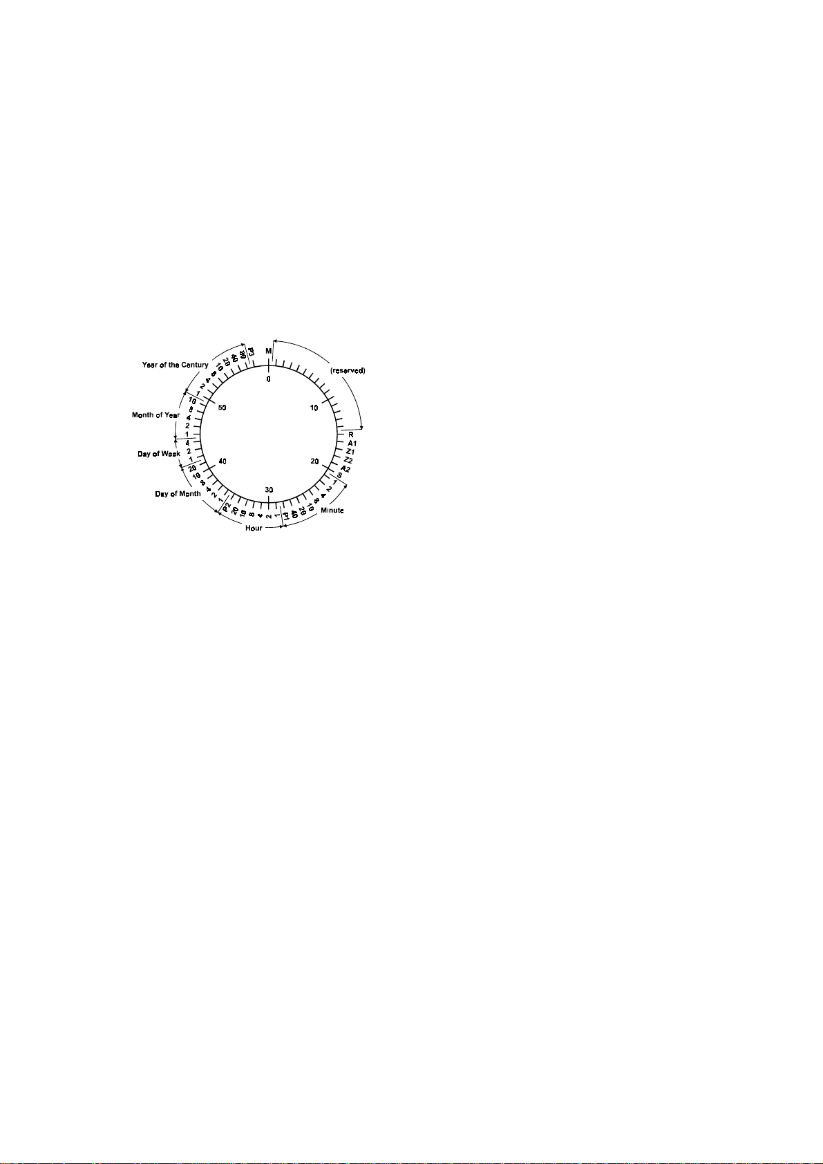
DCF77 Emulation
The GPS167PC satellite controlled clock generates TTL level time marks (active
HIGH) which are compatible with the time marks spread by the German long wave
transmitter DCF77. This long wave transmitter installed in Mainflingen near Frankfurt/Germany transmits the reference time of the Federal Republic of Germany: time
of day, date of month and day of week in BCD coded second pulses. Once every
minute the complete time information is transmitted. However, the clock generates
time marks representing its local time as configured by the user, including announcement of changes in daylight saving and announcement of leap seconds. The coding
sheme is given below:
M Start of Minute (0)
R RF Transmission via secondary antenna (0)
A1 Announcement of a change in daylight saving
Z1, Z2 Time zone identification
Z1,Z2 = 0,1: Daylight saving disabled
Z1,Z2 = 1,0: Daylight saving enabled
A2 Announcement of a leap second
S Start of time code information (1)
P1, P2, P3 Even parity bits
Time marks start at the beginning of a new second. If a binary "0" is to be transmitted,
the length of the corresponding time mark is 100 msec, if a binary "1" is transmitted,
the time mark has a length of 200 msec. The information on the current date and time
as well as some parity and status bits can be decoded from the time marks of the 15th
up to the 58th second every minute. The absence of any time mark at the 59th second
of a minute signals that a new minute will begin with the next time mark. The DCF
emulation output is enabled immediately after power-up.
8
Page 9
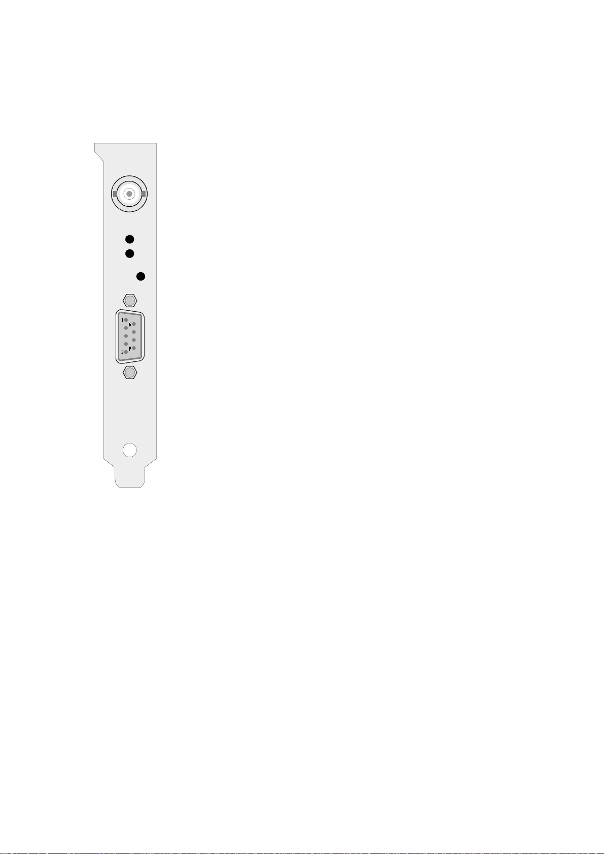
Connectors and LEDs in the Rear Slot Cover
The coaxial antenna connector, two status LEDs and a 9 pin sub
D connector can be found in the rear slot cover. (see figure).
The upper, green LED (LOCK) is turned on when after powerup the receiver has acquired at least four satellites and has
computed its position. In normal operation the receiver position
is updated continuously as long as at least four satellites can be
received.
The lower, red LED (FAIL) is turned on after power-up until
the receiver has synchronized or if a severe error occurs during
operation.
The 9 pin sub D connector is wired to the GPS167PC's serial
port COM0. Pin assignment can be seen from the figure beside.
This port can not be used as serial port for the computer.
Instead, it can be uses to send out Meinberg's standard time
string to an external device. A DIL switch on the board can be
used to wire some TTL inputs or outputs (0..5V) to some
connector pins. In this case, absolute care must be taken if
another device is connected to the port, because voltage
levels of -12V through +12V (as commonly used with RS232 ports) at TTL inputs or outputs may damage the radio
clock.
Behind the little hole in the slot cover there is a push button
which is needed if the clock's firmware shall be updated. See the
chapture about firmware updates for details.
Installing the Radio Clock
Before the clock can be installed in the computer, some configuration may be required
if the desired settings differ from the default settings.
Setting The Port Base Address
Programs can read data from or write data to the board using 2 I/O ports from a block
of four addresses. The base I/O address can be set up in a wide range using the DIL
switch on the board. When being shipped, the board´s address is set to 300h corresponding to the default address used by the utility software. If one of the levers 8, 9, or
9
Page 10

10 of the DIL switch is set to the ON position, the radio clock GPS167PC can generate
cyclic hardware interrupts on the PC's corresponding interrupt line. However, if the
clock is operated using the software shipped with the board, all of the interrupt
switches should remain in the OFF position because the software shipped with the
board does not use any hardware interrupt.
In most cases the board can be installed without modifications. If another board uses I/
O in the range 300h to 303h (e. g. networks boards are often configured with this
address), the clock´s base address must be changed. Lever 1 of the DIL switch is
assigned to the PC's address line A2, lever 7 is assigned to A8, A9 is hard wired to
logical "1". Any switch in the ON position ties the corresponding address line to
logical "0". Some common port base addresses and the corresponding DIL switch
settings are shown in the table below:
Use the table shown below to see the DIL switch settings and corresponding I/O
addresses.
PortSW1234567 PortSW1234567
200 xxxxxxx 32C - -x -xx 204 -xxxxxx 330 xx - -xx 208 x -xxxxx 334 -x - -xx 20C - -xxxxx 338 x - - -xx 210 xx -xxxx 33C - - - -xx 214 - x - x x x x 340 x x x x - x 218 x - - x x x x 344 - x x x - x 21C - - - x x x x 348 x - x x - x 300 xxxxxx - 34C - -xx -x 304 -xxxxx - 350 xx -x -x 308 x -xxxx - 354 -x -x -x 30C - -xxxx - 358 x - -x -x 310 xx -xxx - 35C - - -x -x 314 - x - x x x - 360 x x x - - x 318 x - - x x x - 364 - x x - - x 31C ---xxx- 368 x-x--x320 xxx-xx- 36C --x--x324 - x x - x x - 370 x x - - - x 328 x - x - x x - 374 - x - - - x -
'-' —> switch in pos. ON '-' —> switch in pos. OFF
10
Page 11

Configuring the 9 pin Connector
By default only the signals needed for the serial port COM0 are mapped to the pins of
the connector. Whenever one of the additional signals shall be used, the signal must be
mapped to a pin by putting the appropriate lever of switch DIL2 in the ON position.
The table below shows the pin assignments for the connector and the DIL switch lever
assigned to each of the signals. Care must be taken when mapping a signal to Pin 4 of
the connector. Only one of the switch levers 5 or 10 may be put in the ON position to
connect the pulse per minute or the 10MHz standard frequency to the jack. Those
signals which do not have a lever of the DIL switch assigned are always available at
the connector:
Mounting the Board
The computer has to be turned off and its case must be opened. The radio clock can be
installed in any ISA slot not used yet. The rear slot cover must be removed before the
board can be carefully plugged in. The computer´s case should be closed again and the
antenna can be connected to the coaxial plug at the clock's rear slot cover. After the
computer has been restarted, the monitor software can be run in order to check the
clock's configuration.
Mounting the Antenna
The GPS satellites are not stationary but circle round the globe in a period of about 12
hours. They can only be received if no building is in the line-of-sight from the antenna
to the satellite, so the antenna/converter unit must be installed in a location from which
as much of the sky as possible can be seen. The unit can be mounted using a pole with
a diameter up to 60 mm. A standard coaxial cable with 50 ohms impedance (e.g.
RG58) should be used to connect the antenna/converter unit to the receiver. Cable
thinner than RG58 should be avoided due to its higher DC resistance and RF attenuation. When using the optional antenna diplexer the total length of one antenna line
11
Page 12

between antenna, diplexer and receiver must not be longer than 200m. If a cable with
less attenuation is used its length may be increased accordingly.
Powering Up the System
After the board has been mounted and the antenna has been connected, the system is
ready to operate. About 10 seconds after power-up the receiver´s TCXO operates with
the required accuracy. If the receiver finds valid almanac and ephemeris data in its
battery buffered memory and the receiver´s position has not changed significantly
since its last operation the receiver can find out which satellites are in view now. Only
a single satellite needs to be received to synchronize and generate output pulses, so
synchronization can be achieved at least one minute after power-up. After 20 minutes
of operation the TCXO has achieved its final accuracy and the generated frequencies
are within the spezified tolerances.
If the receiver position has changed by some hundred kilometers since last operation, the satellites´ real elevation and doppler might not match those values expected by
the receiver thus forcing the receiver to start scanning for satellites. This mode is
called Warm Boot because the receiver can obtain ID numbers of existing satellites
from the valid almanac. When the receiver has found four satellites in view it can
update its new position and switch to normal operation. If the almanac has been lost
because the battery had been disconnected the receiver has to scan for a satellite and
read in the current almanacs. This mode is called Cold Boot. It takes 12 minutes until
the new almanac is complete and the system switches to Warm Boot mode scanning
for other satellites.
In the default mode of operation, neither pulse outputs nor the serial ports will be
enabled after power-up until synchronization has been achieved. However, it is
possible to configure some or all of those outputs to be enabled immediately after
power-up. If the system starts up in a new environment (e. g. receiver position has
changed or new power supply) it can take some minutes until the TCXO´s output
frequency has been adjusted. Up to that time accuracy of frequency drops to 10
reducing the accuracy of pulses to ±2µs.
-8
12
Page 13

Files on the Diskette shipped with the Board
DATEIEN.TXT this list of files in German language
LIESMICH.TXT last changes/modifications in German language
FILES.TXT this list of files in English
README.TXT llast changes/modifications in English
@6AAC.ADF Adapter Description File (required for PS31 only)
PCPSINFO.EXE shows continuously the board´s status
PCPSDRV.COM resident driver, keeps computer time synchronized with board time
DRV.EXE temporarily disables the resident driver
DISP.EXE enables or disables the permanent date/time window
POSXY.EXE positions the permanent date/time window on the screen
COLOR.EXE sets the screen attribute of the permanent date/time window
Support for other Operating Systems
Drivers for the operating systems listed below are optionally available:
IBM OS/2 v2.1 and above
Novell NetWare v3.11 and above
Microsoft Windows NT v3.51 and above
Copying the distributed Software to the Hard Disk
When the computer has come up after power on the utility programs should be copied
from the shipped diskette to a subdirectory on the hard disk. Assume the current drive
is C: and the new subdirectory is to be created on the current drive, create that
subdirectory (e.g. called MEINBERG) using the command
MD \MEINBERG
from the DOS command line. Make the new subdirectory the current one using the
command
CD \MEINBERG
13
Page 14

If the utility diskette is inserted in drive A: use the following command to copy the
files and subdirectories from the diskette to the hard disk:
XCOPY A:*.* /S
Using PCPSINFO.EXE
After the board has been installed in the computer the program PCPSINFO.EXE
should be run in order to see if the board has been properly installed. This program can
display its messages in English or in German language and the date and time in
formats used in the USA, the UK, or Germany. The default language and formats used
are derived from the DOS country code at startup. If automatic language detection
does not yield the desired result, you can force a language and date/time format using
a command line parameter or by pressing a function key when the program is running.
The command syntax is shown below:
PCPSINFO [P:xxx] [C:xx] [MONO] [?]
Usage of the command line parameters is described below:
P:xxx This parameter is only needed for clocks with ISA bus, if the I/O port base address
does not match the default I/O add ress (300 hex). If a clock with PCI bus or Microchannel bus is installed then the program will automatically retrieve the I/O address
from the computer's BIOS.
C:xx Country code override. The default country code to be used is derived from the COUN-
TRY=.... entry in the CONFIG.SYS file.
xx may be set to 49 (Germany, 24h clock, dd.mm.yy), 44 (U.K, 12h clock, dd/mm/yy)
or 1 (USA, 12h clock, mm-dd-yy).
MONO Force monochrome display even if color display installed. May increase the readability
on LC displays often used with laptops.
? Displays a message how to setup port address and how to use the program. Output can
be redirected to printer ( append ">LPT1" to the command line) or file (append ">file-
name").
All the command line parameters are optional. In most cases the program is started
simply by entering PCPSINFO. If the board can installed successfully, the screen
displays information similar to figure shown below:
14
Page 15

The upper part of the screen shows information about the resident driver (if the driver
has been installed). These information include the ID string of the resident driver
with the driver revision number, the number of the software interrupt used to
control the resident driver and the last recent date/time the driver has read from the
board. The number of the user interrupt is determined automatically when the resident
driver is installed. It is not affected by the hardware interrupt configured by jumpers.
The BUSY flag controls the driver´s right to access the board. If the flag is set to
OFF the driver is allowed to access the board, if it is ON, access is inhibited. This flag
can be changed from the command line using the utility DRV.EXE or by pressing the
key B in PCPSINFO. The flag DISP affects the resident driver´s feature displaying
the permanent date/time window on the screen (upper right corner in the screenshot
above). It can be altered using the utility DISP.EXE from the command line or by
pressing the key D. The flag Set RTC direct enables the driver to write directly to the
computer´s real time clock. This feature is required in some special environments
only; see the description of PCPSDRV.COM below. The Tick Counter counts the
times the driver has been activated by the computer´s periodic timer tick interrupt. If
this counter is down to zero, the computer´s system time is set and the counter is
reloaded to the Tick Reload value. The tick reload is derived from the update cycle
parameter given in the command line when PCPSDRV.COM is installed. The system
timer generates 18.2 interrupt per second, so the reload value in the figure above (182)
corresponds to an update cycle of 10 seconds.
The lower part of the screen gives information about the radio clock installed in the
computer: The Eprom´s ID string rsp. the type of the board, and the clock's serial
number and port base address, and the settings of the clock's serial ports. The serial
parameters can be set up by menu if the key F4 is being hit.
The field labeled Date/Time: displays the board´s current date and time. If the key
F3 is pressed the user can modify the board´s date and time, should the need arise. The
line Last Sync: shows the time last synchronization with the GPS satellites has been
15
Page 16

achieved. The field labeled Capture: show the time of the last trigger pulse at one of
the clock's capture inputs, if available.
The clock´s current status is shown in the field Status:. The first line shows the
mode of operation and the number of satellites which can be used. By default, the
mode should read Normal Operation. The indicator (8/9 SVs) says that currently 8
out of 9 satellites in view can be received. The next lines display whether time
synchronization has been achieved, whether the receiver position has been computed,
and whether daylight saving is currently in effect or not.
Time zone and daylight saving parameters can be viewed or modified by a dialog
window which comes up if the key F5 is pressed. The example below shows the
settings used in Germany:
The German standard time (MEZ) is computed by adding 1 hour (3600 sec) to UTC.
While daylight saving is active, two hours (7200 sec) must be added to UTC to get
German daylight time (MESZ). Every year, daylight saving starts at the first Sunday
after March, 25, at 2 o'clock, it ends at the first Sunday after October, 25, at 3 o'clock.
The parameters shown in the dialog are saved on the radio clock board if the ENTER
key is pressed to close the dialog.
Pressing both the keys Alt and X simultanously lets this program terminate.
16
Page 17

The resident driver for DOS/Windows
The resident driver PCPSDRV.COM runs with DOS version 2.11 or greater, Windows 3.x, or Windows 9x. It uses only about 1500 bytes of memory and periodically
synchronizes the computer´s system time to the board time. Additionally, the driver is
able to display the board´s time continuously in a window on the text screen. This
feature can be enabled and controlled by some of the utility programs (see next
chapter).
In order to avoid conflicts accessing the board the driver should not be installed or
be temporarily disabled using the utility DRV.EXE if user-written software accesses
the board.
If the driver has to be installed every boot time, it should be called from the
AUTOEXEC.BAT which should reside in the root directory of the boot drive. Assuming the driver file can be found in the directory MEINBERG on drive C:, a
command line like that shown below should be added to the AUTOEXEC.BAT using
any text editor:
C:\MEINBERG\PCPSDRV [port] [U:xxxx] [I] [R]
The parameter port is only needed for clocks with ISA bus, if the I/O port base
address does not match the default I/O address (300 hex). If a clock with PCI bus or
Microchannel bus is installed then the program will automatically retrieve the I/O
address from the computer's BIOS.
The optional parameter U:xxxx can be used to set the time span to be used for the
periodical update of the system time. Valid numbers for xxxx are 1 to 3600 (seconds).
If this parameter is omitted the time span defaults to 1800 seconds (= 30 minutes).
By default the driver will adjust the computer´s system time only if the clock has
synchronized at least once after power-up (Status: Synchronized after last Reset). If
the clock is installed in an environment where the RF signal can not be received
properly the parameter I may be given on the command line to let the driver ignore
that status flag and adjust system time even if the clock has not synchronized after
power-up.
The last parameter R tells the resident driver to set the real time clock in AT
compatible computers directly. This is only required if the DOS/BIOS interrupts
which modify the computer´s time are redirected by other applications as on Novell
Netware 2.xx file servers. In the default case this parameter should not be used in
order to minimize the execution time of the resident driver.
17
Page 18

Controlling the Resident Driver
If the resident driver PCPSDRV.COM has been installed, some of the utility programs can be used to control the way it works. The programs described below show a
few help lines when they are called without command line parameters.
DRV.EXE temporarily disables the resident driver´s access to the board.
Command: DRV ON or DRV OFF
Default: enabled
DISP.EXE enables or disables the date/time window on the screen.
Command: DISP ON or DISP OFF
Default: disabled
COLOR.EXE sets up the screen attribute of the date/time window
Command: COLOR fg bg
with fg and bg the color numbers of the foreground/background
Default: white characters on black
POSXY.EXE sets up the screen position of the date/time window.
Command: POSXY column row
Default: upper right corner of the screen
Using these utilities, you can enable or disable the date/time window only when
special applications are run.
Firmware Updates
Whenever the on-board software must be upgraded or modified, the new firmware can
be downloaded to the internal flash memory via the radio clock's serial port COM0.
There is no need to open the computer case and insert a new EPROM.
If the button behind a hole in the rear slot cover is pressed for approximately 2
seconds, a bootstrap loader is activated and waits for instructions from the serial port
COM0. A loader program shipped together with the file containing the image of the
new firmware sends the new firmware from one of the computer's serial ports to the
clock's serial port COM0. The bootstrap loader does not depend on the contents of the
flash memory, so if the update procedure is interrupted, it can easily be repeated.
The contents of the program memory will not be modified until the loader program
has sent the command to erase the flash memory. So if the button has been pressed
accidentally, the system will be ready to operate again after the computer has been
turned off an the on again.
18
Page 19

Replacing the Lithium Battery
The life time of the lithium battery on the board is at least 10 years. If the need arises
to replace the battery, the following should be noted:
ATTENTION!
Danger of explosion in case of inadequate replacement of
the lithium battery. Only identical batteries or batteries
recommended by the manufacturer must be used for
replacement. The waste battery must be disposed as pro-
posed by the manufacturer of the battery.
CE Label
This device conforms to the directive 89/336/EWG on the approximation of the laws of the Member States of the European Community
relating to electromagnetc compatibility.
19
Page 20

20
Page 21

Technical Specifications GPS167PC
RECEIVER: Five channel C/A code receiver with external antenna/converter
unit
ANTENNA: Antenna/converter unit with remote power supply
refer to chapter "Technical Specifications of Antenna"
ANTENNA
INPUT: Antenna circuit dc-insulated; dielectric strength: 1000V
Length of cable: refer to chapter "Mounting the Antenna"
TIME TO SYNCHRONIZATION: one minute with known receiver position and valid almanac
12 minutes if invalid battery buffered memory
PULSE
OUTPUTS: change of second (P_SEC, TTL level)
change of minute (P_MIN, TTL level)
ACCURACY OF
PULSES: better than ±250 nsec after synchronization and 20 minutes of
operation
better than ±2 µsec during the first 20 minutes of operation
TIME CAPTURE
INPUTS: triggered on falling TTL slope
Interval of events: 1.5msec min.
Resolution: 100ns
FREQUENCY
OUTPUTS: 10 MHz (TTL level)
STANDARD
ACCURACY OF
FREQUENCY: ±5.10
-9
21
Page 22

ACCURACY OF
FREQUENCY
OPTION OCXO: after sync. and 20 min of operation ±1
during first 20 minutes of operation ±2.10
Accuracy of quartz
one day, free-running ±2.10
one year, free-running ±5.10
Short term stability
<= 10 sec, GPS controlled ±1.10
<= 10 sec, free running ±3.10
Temperature drift
free running ±2.10
SSB phase noise
10 kHz beside carrier -101 dB/Hz
1 kHz beside carrier -76 dB/Hz
100 Hz beside carrier -60 dB/Hz
.
10
-9
-8
-8
-7
-9
-9
-7
SERIAL PORTS: 2 asynchronous serial ports (RS-232)
Baud Rate: 300 up to 19200
Framing: 7N2, 7E1, 7E2, 8N1, 8N2, 8E1
default setting: COM0: 19200, 8N1
COM1: 9600, 8N1
POWER
REQUIREMENTS: 5V ± 5%, @280mA
12V ± 5%, @180mA
RF CONNECTOR: coaxial BNC
AMBIENT
TEMPERATURE: 0 ... 60°C
HUMIDITY: 85% max.
22
Page 23

Technical Specifications of Antenna
ANTENNA: dielectrical patch antenna, 25 x 25mm
receive frequency: 1575.42 MHz
bandwidth: 9 MHz
CONVERTER: local oscillator to converter frequency: 10 MHz
first IF frequency: 35.4 MHz
POWER
REQUIREMENTS: 12V ... 18V, @ 100mA (provided via antenna cable)
CONNECTOR: coax type N, female
AMBIENT
TEMPERATURE: -25 ... +65°C
HOUSING: ABS plastic case for outdoor installation (IP56)
PHYSICAL
DIMENSION:
23
Page 24

Assembly with CN-UB/E (CN-UB-280DC)
GPS167
Antenna
Type N
male
As short as possible!
1.5m max.
Type N
male
Type N
male
CN-UB/E
Type N / BNC
male
Meinberg
GPS
24
Page 25

Format of the Meinberg Standard Time String
The Meinberg Standard Time String is a sequence of 32 ASCII characters starting
with the STX (start-of-text) character and ending with the ETX (end-of-text) character. The format is:
<STX>D:dd.mm.yy;T:w;U:hh.mm.ss;uvxy<ETX>
The letters printed in italics are replaced by ASCII numbers whereas the other
characters are part of the time string. The groups of characters as defined below:
<STX> Start-Of-Text (ASCII code 02h)
dd.mm.yy the current date:
dd day of month (01..31)
mm month (01..12)
yy year of the century (00..99)
w the day of the week (1..7, 1 = Monday)
hh.mm.ss the current time:
hh hours (00..23)
mm minutes (00..59)
ss seconds (00..59, or 60 while leap second)
uv clock status characters:
u: ‘#’ clock has not synchronized after reset
‘ ‘ (space, 20h) clock has synchronized after reset
v: different for DCF77 or GPS receivers:
‘*’ DCF77 clock currently runs on XTAL
GPS receiver has not checked its position
‘ ‘ (space, 20h) DCF77 clock is sync'd with transmitter
GPS receiver has determined its position
x time zone indicator:
‘U’ UTC Universal Time Coordinated, formerly GMT
‘ ‘ MEZ European Standard Time, daylight saving disabled
‘S’ MESZ European Summertime, daylight saving enabled
y anouncement of discontinuity of time, enabled during last hour
before discontinuity comes in effect:
‘!’ announcement of start or end of daylight saving time
‘A’ announcement of leap second insertion
‘ ‘ (space, 20h) nothing announced
<ETX> End-Of-Text (ASCII code 03h)
25
Page 26

Format of the Meinberg Capture String
The Meinberg Capture String is a sequence of 31 ASCII characters terminated by a
CR/LF (Carriage Return/Line Feed) combination. The format is:
CHx_tt.mm.jj_hh:mm:ss.fffffff<CR><LF>
The letters printed in italics are replaced by ASCII numbers whereas the other
characters are part of the time string. The groups of characters as defined below:
x 0 or 1 corresponding on the number of the capture input
_ ASCII space 20h
dd.mm.yy the capture date:
dd day of month (01..31)
mm month (01..12)
yy year of the century (00..99)
hh:mm:ss.fffffff the capture time:
hh hours (00..23)
mm minutes (00..59)
ss seconds (00..59, or 60 while leap second)
fffffff fractions of second, 7 digits
<CR> Carriage Return, ASCII code 0Dh
<LF> Line Feed, ASCII code 0Ah
Assignment of the 5 Pin Jumper Block
The jumper block can be used to access the 10 MHz frequency output and the serial
port COM1. Pin 5 is located near the board's bus connector:
26
Page 27

Component Layout GPS167PC
27
Page 28

 Loading...