

Page 1

GPS167
Technical Information
Operating Instructions
Page 2

Impressum
Meinberg Funkuhren GmbH & Co. KG
Auf der Landwehr 22
D-31812 Bad Pyrmont
Phone: +49 (0) 52 81 / 9309-0
Fax: +49 (0) 52 81 / 9309-30
April 25, 2006
Page 3

Table of Contents
Impressum ............................................................................................ 2
General Information ............................................................................. 6
GPS167 Features .................................................................................. 7
Time Zone and Daylight Saving................................................. 8
Pulse and Frequency Outputs ..................................................... 8
Time Capture Inputs ................................................................... 9
Asynchronous Serial Ports (optional 4x COM).......................... 9
DCF77 Emulation ..................................................................... 10
Programmable pulse (optional) ................................................ 11
Timecode outputs (optional)..................................................... 11
Abstract ........................................................................... 11
Installation .......................................................................................... 12
Power Supply ............................................................................ 12
Mounting the Antenna .............................................................. 12
Antenna Short-Circuit .............................................................. 13
Assembly with CN-UB/E (optional) ........................................ 14
Powering Up the System .......................................................... 15
The Front Panel Layout ..................................................................... 16
FAIL LED ................................................................................ 16
LOCK LED .............................................................................. 16
LC Display ................................................................................ 16
MENU Key ............................................................................... 16
CLR/ACK Key ......................................................................... 16
NEXT Key ................................................................................ 17
INC Key .................................................................................... 17
Page 4

The Menus in Detail ........................................................................... 17
Root Menu ................................................................................ 17
Menu RECEIVER POS. ........................................................... 19
Menu SV CONSTELLATION ................................................. 19
Menu SV POSITION ............................................................... 20
Menu USER CAPTURE .......................................................... 20
Menu SETUP............................................................................ 20
SETUP FREQUENCY OUTPUT................................... 21
SETUP ENABLE OUTPUTS ........................................ 21
SETUP TIME ZONE ...................................................... 22
SETUP DAYLIGHT SAV ON/OFF .............................. 22
SETUP SERIAL PORT PARM ...................................... 23
SETUP SERIAL STRING TYPE ................................... 24
SETUP SERIAL STRING MODE ................................. 24
SETUP POUT X (optional) ............................................ 25
Mode ...................................................................... 25
Timer mode............................................................ 25
Single Pulse ........................................................... 26
Cyclic mode ........................................................... 26
PPS, PPM, PPH Modes ......................................... 26
Menu Quick Reference for progr. Pulse ................ 27
SETUP IRIG SETTINGS (optional) .............................. 28
SETUP INITIAL POSITION ......................................... 28
SETUP INITIAL TIME .................................................. 29
INIT USER PARMS ....................................................... 29
INIT GPS PARMS .......................................................... 29
FORCE BOOT MODE ................................................... 30
ANTENNA CABLE ....................................................... 30
Resetting Factory Defaults ................................................................. 31
Page 5

Firmware Updates .............................................................................. 31
Skilled/Service-Personnel only: Replacing the Lithium Battery ....... 32
CE Label ............................................................................................ 32
Technical Specifications GPS167 ...................................................... 33
Oscillator specifications............................................................ 35
Technical Specifications GPS167 Antenna .............................. 36
Time Strings ............................................................................. 37
Format of the Meinberg Standard Time String ............... 37
Format of the Meinberg Capture String .......................... 38
Format of the SAT Time String ...................................... 39
Format of the Uni Erlangen String (NTP) ...................... 40
Format of the NMEA 0183 String (RMC) ...................... 42
Format of the ABB SPA Time String ............................. 43
Format of the Computime Time String........................... 44
Timecode (optional) ................................................................. 45
Principle of Operation ..................................................... 45
Block Diagram Timecode ............................................... 45
IRIG Standard Format ..................................................... 46
AFNOR Standard Format ............................................... 47
Assignment of CF Segment in IEEE1344 mode............. 48
Generated Timecodes ...................................................... 49
Selection of Generated Time Code ........................ 50
Outputs ............................................................................ 50
AM Sine Wave Output ........................................... 50
PWM DC Outputs .................................................. 50
Technical Data ................................................................ 51
Signal Description GPS167 V7.x ............................................. 52
Rear Connector Pin Assignments GPS167 V7.x ...................... 53
Menu Quick Reference ...................................................................... 55
Page 6

6
General Information
The satellite receiver clock GPS167 has been designed to provide extremly precise
time to its user. The clock has been developed for applications where conventional
radio controlled clocks can´t meet the growing requirements in precision. High
precision available 24 hours a day around the whole world is the main feature of the
new system which receives its information from the satellites of the Global Positioning System.
The Global Positioning System (GPS) is a satellite-based radio-positioning, navigation, and time-transfer system. It was installed by the United States Departement of
Defense and provides two levels of accuracy: The Standard Positioning Service (SPS)
and the Precise Positioning Service (PPS). While PPS is encrypted and only available
for authorized (military) users, SPS has been made available to the general public.
GPS is based on accurately measuring the propagation time of signals transmitted
from satellites to the user´s receiver. A nominal constellation of 21 satellites together
with several active spares in six orbital planes 20000 km over ground provides a
minimum of four satellites to be in view 24 hours a day at every point of the globe.
Four satellites need to be received simultaneously if both receiver position (x, y, z)
and receiver clock offset from GPS system time must be computed. All the satellites
are monitored by control stations which determine the exact orbit parameters as well
as the clock offset of the satellites´ on-board atomic clocks. These parameters are
uploaded to the satellites and become part of a navigation message which is retransmitted by the satellites in order to pass that information to the user´s receiver.
The high precision orbit parameters of a satellite are called ephemeris parameters
whereas a reduced precision subset of the ephemeris parameters is called a satellite´s
almanac. While ephemeris parameters must be evaluated to compute the receiver´s
position and clock offset, almanac parameters are used to check which satellites are in
view from a given receiver position at a given time. Each satellite transmits its own set
of ephemeris parameters and almanac parameters of all existing satellites.
6
Page 7

7
GPS167 Features
The hardware of GPS167 is a 100mm x 160mm microprocessor board. The 105mm
wide front panel integrates a 4 x 16 character LC display, two LED indicators and 4
push buttons. The receiver is connected to the antenna/converter unit by a 50 ohm
coaxial cable (refer to "Mounting the Antenna"). Feeding the antenna/converter occurs DC insulated via the antenna cable. Optional an antenna splitter for up to four
receivers connected to one antenna is available.
GPS167 is using the "Standard Positioning Service" SPS. The navigation message
coming in from the satellites is decoded by GPS167´s microprocessor in order to track
the GPS system time. Compensation of the RF signal´s propagation delay is done by
automatical determination of the receiver´s position on the globe. A correction value
computed from the satellites´ navigation messages increases the accuracy of the
board´s oven controlled master oscillator (OCXO) and automatically compensates the
OCXO´s aging. The last recent value is restored from the battery buffered memory at
power-up.
The GPS167 provides different optional outputs, i.e. three progammable pulse
outputs, modulated/unmodulated timecode output, and up to a total of four RS232
COM ports. Additionally, you can order the GPS167 with different OCXOs (e.g.
OCXO-LQ / MQ / HQ or an external Rubidium) to match the required accuracy.
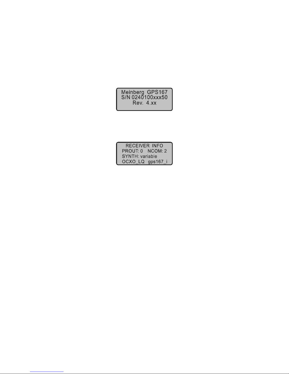
The hard- and software configuration of the clock is dis-
played if the NEXT key is pressed two times from the root
menu.
Page 8

8
Time Zone and Daylight Saving
GPS system time differs from the universal time scale UTC (Universal Time Coordi-
nated) by the number of leap seconds which have been inserted into the UTC time
scale after GPS has been initiated in 1980. The current number of leap seconds is part
of the navigation message supplied by the satellites, so GPS167´s internal real time is
based on UTC. Conversion to local time including handling of daylight saving year by
year can be done by the receiver´s microprocessor if the corresponding parameters are
set up by the user.
Pulse and Frequency Outputs
The pulse generator of GPS167 generates pulses once per second (P_SEC) and once
per minute (P_MIN). Additionally, master frequencies of 10 MHz, 1 MHz and 100
kHz are derived from the OCXO. All the pulses are available with TTL level at the
rear connector. The included synthesizer generates a frequency from 1/8 Hz up to 10
MHz synchronous to the internal timing frame. The phase of this output can be shifted
from -360° to +360° for frequencies less than 10 kHz. Both frequency and phase can
be setup from the front panel or using the serial port COM0. Synthesizer output is
available at the rear connector as sine-wave output (F_SYNTH_SIN), with TTL level
(F_SYNTH) and via an open drain output (F_SYNTH_OD). The open drain output
can be used to drive an optocoupler when a low frequency is generated.
In the default mode of operation, pulse outputs and the synthesizer output are
disabled until the receiver has synchronized after power-up. However, the system can
be configured to enable those outputs immediately after power-up. An additional TTL
output (TIME_SYN) reflects the state of synchronization. This output switches to
TTL HIGH level when synchronization has been achieved and returns to TTL LOW
level if not a single satellite can be received or the receiver is forced to another mode
of operation by the user.
Page 9

9
Time Capture Inputs
Two time capture inputs called User Capture 0 and 1 are provided at the rear connector
(CAP0 and CAP1) to measure asynchronous time events. A falling TTL slope at one
of these inputs lets the microprocessor save the current real time in its capture buffer.
From the buffer, capture events are transmitted via COM0 or COM1 and displayed on
LCD. The capture buffer can hold more than 500 events, so either a burst of events
with intervals down to less than 1.5 msec can be recorded or a continuous stream of
events at a lower rate depending on the transmission speed of COM0 or COM1 can be
measured. The format of the output string is ASCII, see the technical specifications at
the end of this document for details. If the capture buffer is full a message "** capture
buffer full" is transmitted, if the interval between two captures is too short the warning
"** capture overrun" is being sent.
Asynchronous Serial Ports (optional 4x COM)
Four asynchronous serial RS232 interfaces (COM0 ... COM3) are available to the
user. In the default mode of operation, the serial outputs are disabled until the receiver
has synchronized after power-up. However, the system can be configured to enable
those outputs immediately after power-up. Transmission speeds, framings and mode
of operation can be configured separately using the setup menu. COM0 is compatible
with other radio remote clocks made by Meinberg. It sends the time string either once
per second, once per minute or on request with ASCII ´?´ only. Also the interfaces can
be configured to transmit capture data either automatically when available or on
request. The format of the output strings is ASCII, see the technical specifications at
the end of this document for details. A separate document with programming instructions can be requested defining a binary data format which can be used to exchange
parameters with GPS167 via COM0.
Page 10

10
DCF77 Emulation
The GPS167 satellite controlled clock generates TTL level time marks (active HIGH)
which are compatible with the time marks spread by the German long wave transmitter DCF77. This long wave transmitter installed in Mainflingen near Frankfurt/
Germany transmits the reference time of the Federal Republic of Germany: time of
day, date of month and day of week in BCD coded second pulses. Once every minute
the complete time information is transmitted. However, GPS167 generates time marks
representing its local time as configured by the user, including announcement of
changes in daylight saving and announcement of leap seconds. The coding sheme is
given below:
M Start of Minute (0.1 s)
R RF Transmission via secondary antenna
A1 Announcement of a change in daylight saving
Z1, Z2 Time zone identif ication
Z1, Z2 = 0, 1: Daylight saving disabled
Z1, Z2 = 1, 0: Daylight saving enabled
A2 Announcement of a leap second
S Start of time code in formation
P1, P2, P3 Even parity bits
0
10
20
30
40
50
R
M
1
4
2
1
2
0
1
0
8
4
2
1
P
2
2
0
1
0
8
4
2
1
2
4
8
1
0
1
2
4
8
1
0
2
0
4
0
8
0
P
3
A
1
Z
1
Z
2
A
2
S
1
2
4
8
1
0
2
0
4
0
P
1
Minute
(reserved)
Hour
Day of Month
Day of Week
Year of the Century
Month of Year
Time marks start at the beginning of new second. If a binary "0" is to be transmitted,
the length of the corresponding time mark is 100 msec, if a binary "1" is transmitted,
the time mark has a length of 200 msec. The information on the current date and time
as well as some parity and status bits can be decoded from the time marks of the 15th
up to the 58th second every minute. The absence of any time mark at the 59th second
of a minute signals that a new minute will begin with the next time mark. The DCF
emulation output is enabled immediately after power-up.
Page 11

11
Programmable pulse (optional)
At the male connector Typ VG64 there are three programmable TTL outputs (Prog
Pulse 0-2), which are arbitrarily programmable.
Other technical details are described at the end of this manual.
Timecode outputs (optional)
Abstract
The transmission of coded timing signals began to take on widespread importance
in the early 1950´s. Especially the US missile and space programs were the forces
behind the development of these time codes, which were used for the correlation of
data. The definition of time code formats was completely arbitrary and left to the
individual ideas of each design engineer. Hundreds of different time codes were
formed, some of which were standardized by the "Inter Range Instrumentation Group"
(IRIG) in the early 60´s.
Except these "IRIG Time Codes", other formats like NASA36, XR3 or 2137 are still
in use. The board GPS167 however generates the IRIG-B, AFNOR NFS 87-500 code
as well as IEEE1344 code which is an IRIG-B123 coded extended by information for
time zone, leap second and date. Other formats may be available on request.
At the male connector Typ VG64 there are also IRIG-B modulated (3Vpp into 50
Ohm) and IRIG-B unmodulated DC level shift.
Page 12
12
Installation
Power Supply
The power supply used with GPS167 has to provide only one output of +5V. The
output voltage should be well regulated because drifting supply voltages reduce the
short time accuracy of the generated frequencies and timing pulses. The power supply
lines should have low resistance and be connected using both pins a and c of the rear
connector.
Mounting the Antenna
The GPS satellites are not stationary but circle round the globe in a period of about 12
hours. They can only be received if no building is in the line-of-sight from the antenna
to the satellite, so the antenna/converter unit must be installed in a location from which
as much of the sky as possible can be seen. The best reception is given when the
antenna has a free view of 8° angular elevation above horizon. If this is not possible
the antenna should be installed with a mostly free view to the equator because of the
satellite courses which are located between latitudes of 55° North and 55° South. If
even this is not possible problems occure especially when at least four sattelites for
positioning have to be found.
The antenna/converter unit can be mounted on a pole with a diameter up to 60 mm
or at a wall. A 50cm plastic tube, two holders for wall-mounting and clamps for polemounting are added to every GPS167. A standard coaxial cable with 50 ohms
impedance should be used to connect the antenna/converter unit to the receiver. The
maximum lenght of cable between antenna and receiver depends on the attenuation
factor of the used coaxial cable.
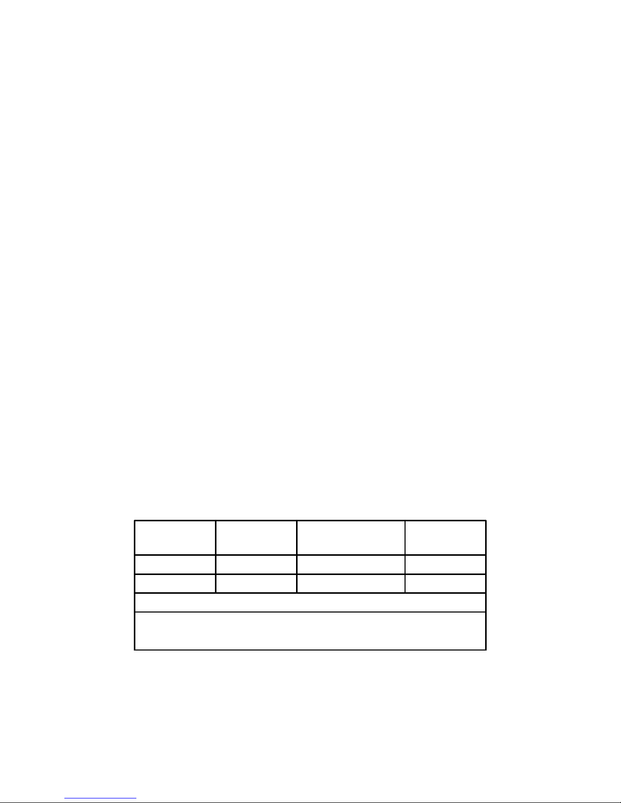
Example:
Type of cable diameter
Ø [mm]
Attenuation at 100MHz
[dB]/100m
max. lenght
[m]
RG58/CU 5mm 15.9 300
1
RG213 10.5mm 6.9 700
1
1)This specifications are made for antenna/converter units produced after January, 2005
The values are typically ones; the exact ones are to find out from the data sheet of the
used cable.
Up to four GPS167 receivers can be run with one antenna/converter unit by using the
optional antenna diplexer. The total length of one antenna line between antenna,
diplexer and receiver must not be longer than the max. lenght shown in the table
above. The position of the diplexer in the antenna line does not matter.
Page 13
13
When installing the high voltage protector CN-UB/E (CN-UB-280DC) be aware to set
it directly after reaching indoor. The CN-UB/E is not for outdoor usage.
Antenna Short-Circuit
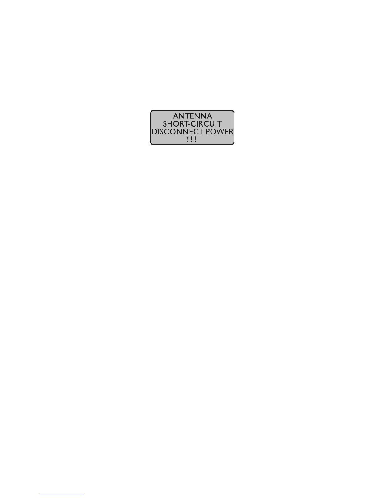
In case of an antenna line short-circuit the following message appears in the display:
If this message appears the clock has to be disconnected from the mains and the defect
is to eliminate. After that the clock can be powered-up again. The antenna supply
voltage must be in a range of 18.5VDC (free) and 16V
DC
(connected GPS antenna).
Page 14
14
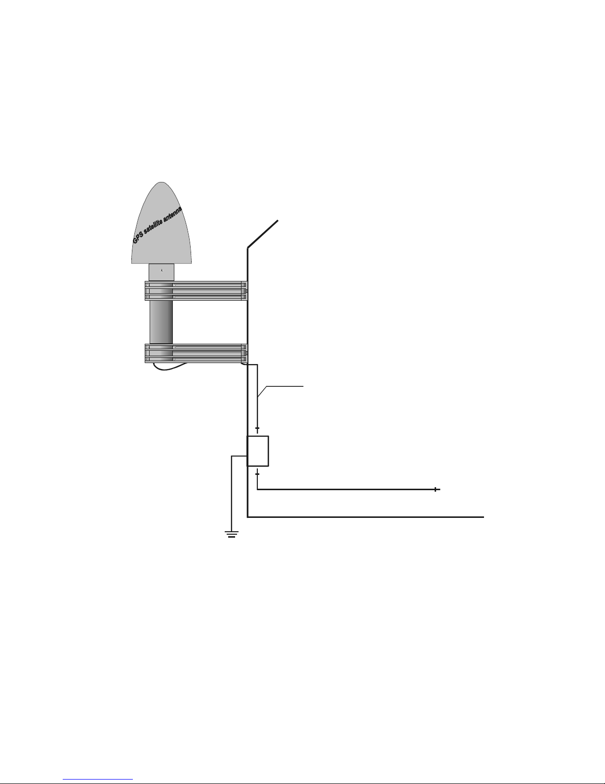
Assembly with CN-UB/E (optional)
Optional the overvoltage protector CN-UB/E is available. Standard you connect the
antenna converter directly with the antenna cable to the system.
N-Norm/BNC
Stecker
N-Norm
Stecker
N-Norm
Stecker
CN-UB/E
max. 1.5m
N-Norm
Stecker
GPS167
Antenne
Meinberg
GPS
möglichst kurz!
Page 15

15
Powering Up the System
If both the antenna and the power supply have been connected the system is ready to
operate. About 10 seconds after power-up the receiver´s (OCXO-LQ) until 3 minutes
(OCXO-MQ / HQ) has warmed up and operates with the required accuracy. If the
receiver finds valid almanac and ephemeris data in its battery buffered memory and
the receiver´s position has not changed significantly since its last operation the
receiver can find out which satellites are in view now. Only a single satellite needs to
be received to synchronize and generate output pulses, so synchronization can be
achieved maximally one minute after power-up (OCXO-LQ) until 10 minutes
(OCXO-MQ / HQ) . After 20 minutes of operation the OCXO is full adjusted and the
generated frequencies are within the spezified tolerances.
If the receiver position has changed by some hundred kilometers since last operation, the satellites´ real elevation and doppler might not match those values expected by
the receiver thus forcing the receiver to start scanning for satellites. This mode is
called Warm Boot because the receiver can obtain ID numbers of existing satellites
from the valid almanac. When the receiver has found four satellites in view it can
update its new position and switch to Normal Operation. If the almanac has been lost
because the battery had been disconnected the receiver has to scan for a satellite and
read in the current almanacs. This mode is called Cold Boot. It takes 12 minutes until
the new almanac is complete and the system switches to Warm Boot mode scanning
for other satellites.
In the default mode of operation, neither pulse and synthesizer outputs nor the serial
ports will be enabled after power-up until synchronization has been achieved. However, it is possible to configure some or all of those outputs to be enabled immediately
after power-up. If the system starts up in a new environment (e. g. receiver position
has changed or new power supply) it can take some minutes until the OCXO´s output
frequency has been adjusted. Up to that time accuracy of frequency drops to 10
-8
reducing the accuracy of pulses to ±5µs.
Page 16

16
The Front Panel Layout
FAIL LED
The FAIL LED is turned on whenever the
TIME_SYN output is low (receiver is not synchronized).
LOCK LED
The LOCK LED is turned on when after powerup the receiver has acquired at least four satellites and has computed its position. In normal
operation the receiver position is updated continuously as long as at least four satellites can be
received.
LC Display
The 4 x 16 character LC display is used to show the receiver´s status and let the user
edit parameters. The keys described below let the user select the desired menu. The
next chapter lists all available menus in detail. A quick reference of the available
menus and submenus can be found at the end of this document.
MENU Key
This key lets the user step through several display menus showing specific data.
CLR/ACK Key
This key has to be used when parameters are to be modified. When this key is pressed
the parameters that have been edited are saved in the battery buffered memory. If the
menu is left without pressing CLR/ACK all changes are discarded.
NEXT INC
CLR
ACK
MENU
FAIL LOC K
Page 17
17
NEXT Key
When editing parameters (LCD cursor is visible) this key moves the cursor to the next
digit rsp. to the next parameter to be edited. If the current menu just displays data
(cursor not visible) pressing this key switches to a submenu (if available).
INC Key
When editing parameters this key increments the digit or letter at the cursor position.
The Menus in Detail
Root Menu
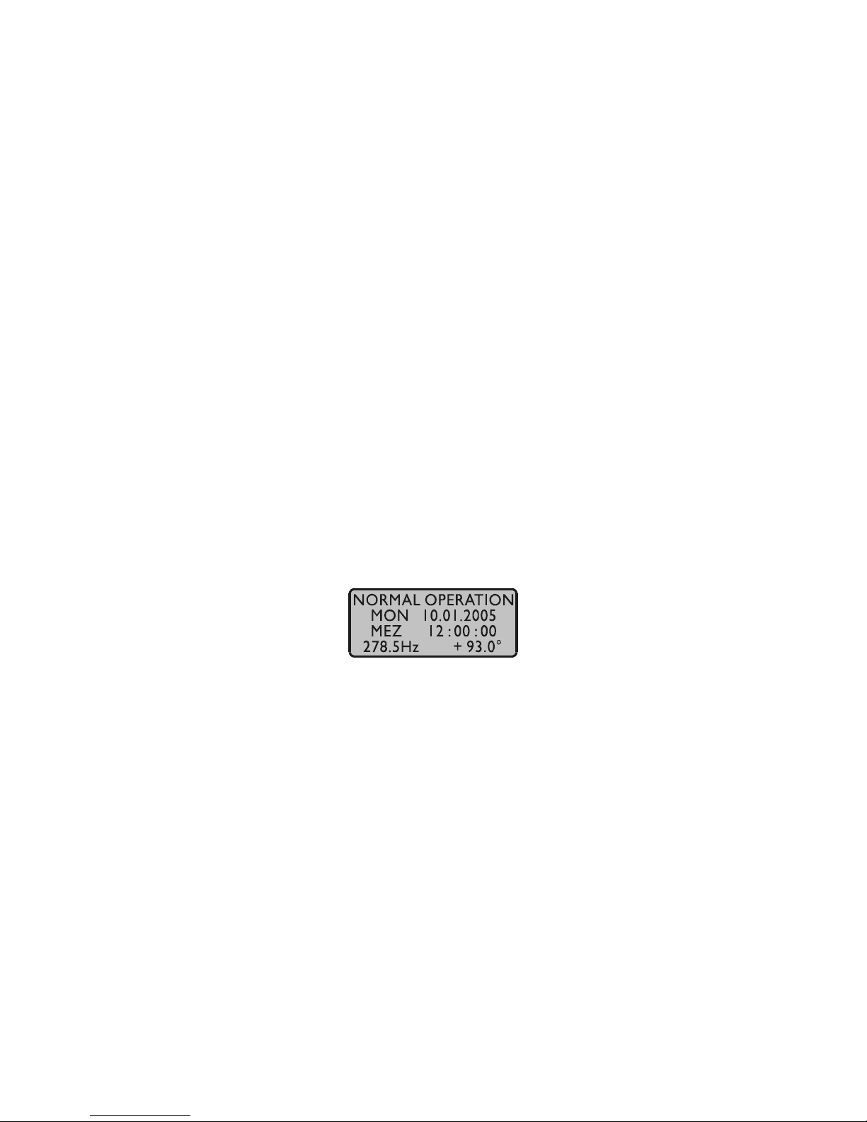
The root menu is shown when the receiver has completed initialization after powerup. The first line of the display shows the receiver´s mode of operation as described
above. The text "NORMAL OPERATION" might be replaced by "COLD BOOT",
"WARM BOOT", "UPDATE ALMANAC". If the antenna is disconnected or not
working properly, the text "ANTENNA FAULTY" is displayed instead.
The next two lines display the current date, the name of the time zone (as defined in
the setup menu) and local time. The last line shows the state of the synthesizer. It
might look like following:
"Synth disabled" Synthesizer is disabled (frequency setted on 0.000)
"F.synth inhibited" GPS167 is not synchronized jet, but the synthesizer will be en-
abled after synchronisation.
"..............(free)" The frequency is generated, but the phase is not synchronous
to the pulse output P_SEC, either because the synthesizer is
enabled although GPS167 has not synchronosized jet or be
cause the frequency is setted to more than 10kHz.
Page 18
18
"..............(drft)" The frequency is generated and the phase was already syn-
chronous to the pulse output P_SEC, but in the moment the
phase can´t be controlled or adjusted because no satellite is
received now.
If the NEXT key is pressed one time from the root menu a submenu is displayed
showing the receiver´s software revision:
If the NEXT key is pressed for second time a submenu is displayed showing other
receiver´s infos
Meaning of the abbreviations and adjusted standard value:
"PROUT: 0" programmable pulse
standard: 0 (not available)
optional: 3 (until three prog. pulse)
"NCOM: 2" serial interface
standard: 2 (COM0 and COM1)
optional: 4 (COM0 - 3)
"SYNTH: variable" frequency synthesizer
standard: available
optional: N/A (only TCXO)
"OCXO_LQ" used oscillator (see Oscillatorspecifikations)
"GPS167_i" EPLD Version
Page 19
19
Menu RECEIVER POS.
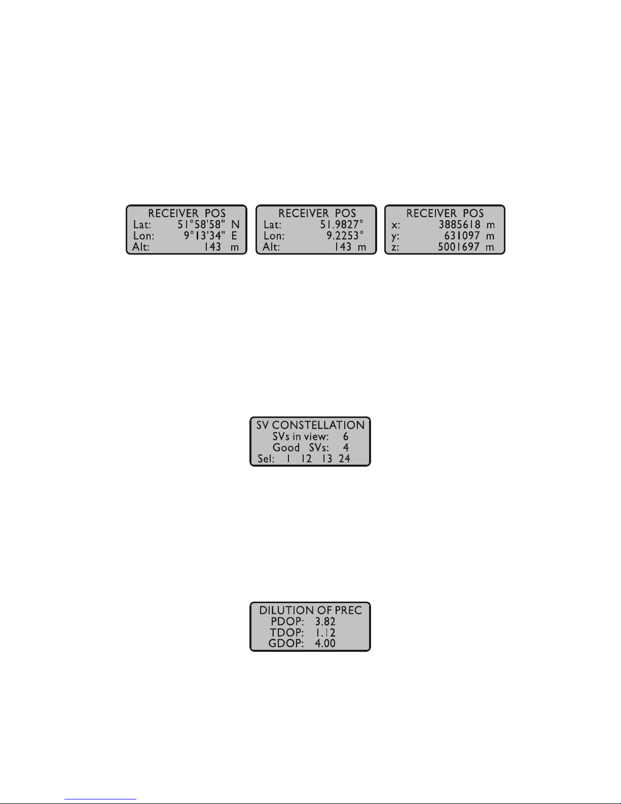
This menu shows the current receiver position. The NEXT key lets the user select one
of three formats. The default format is geographic latitude, longitude and altitude with
latitude and longitude displayed in degrees, minutes and seconds. The next format is
geographic, too, with latitude and longitude displayed in degrees with fractions of
degrees. The third format displays the receiver position in earth centered, earth fixed
coordinates (ECEF coordinates). The three formats are shown below:
Menu SV CONSTELLATION
The SV constellation menu gives an overview of the current satellites (SVs) in view.
The second line of the display shows the number of satellites with an elevation of 5° or
more. The third line gives the number of satellites that can be used for navigation
whereas the last line shows the selected set of satellites which are used to update the
receiver position.
The precision of the computed receiver position and time is affected by the geometric
constellation of the four satellites beeing used. A set of values called dilutions of
precision (DOP) can be computed from the geometric constellation. Those values can
be displayed in a submenu of the SV constellation menu. PDOP is the position dilution
of precision, TDOP is the time dilution of precision, and GDOP, computed from the
others above, is the general dilution of precision. Lower DOP values mean more
precision.
Page 20
20
Menu SV POSITION
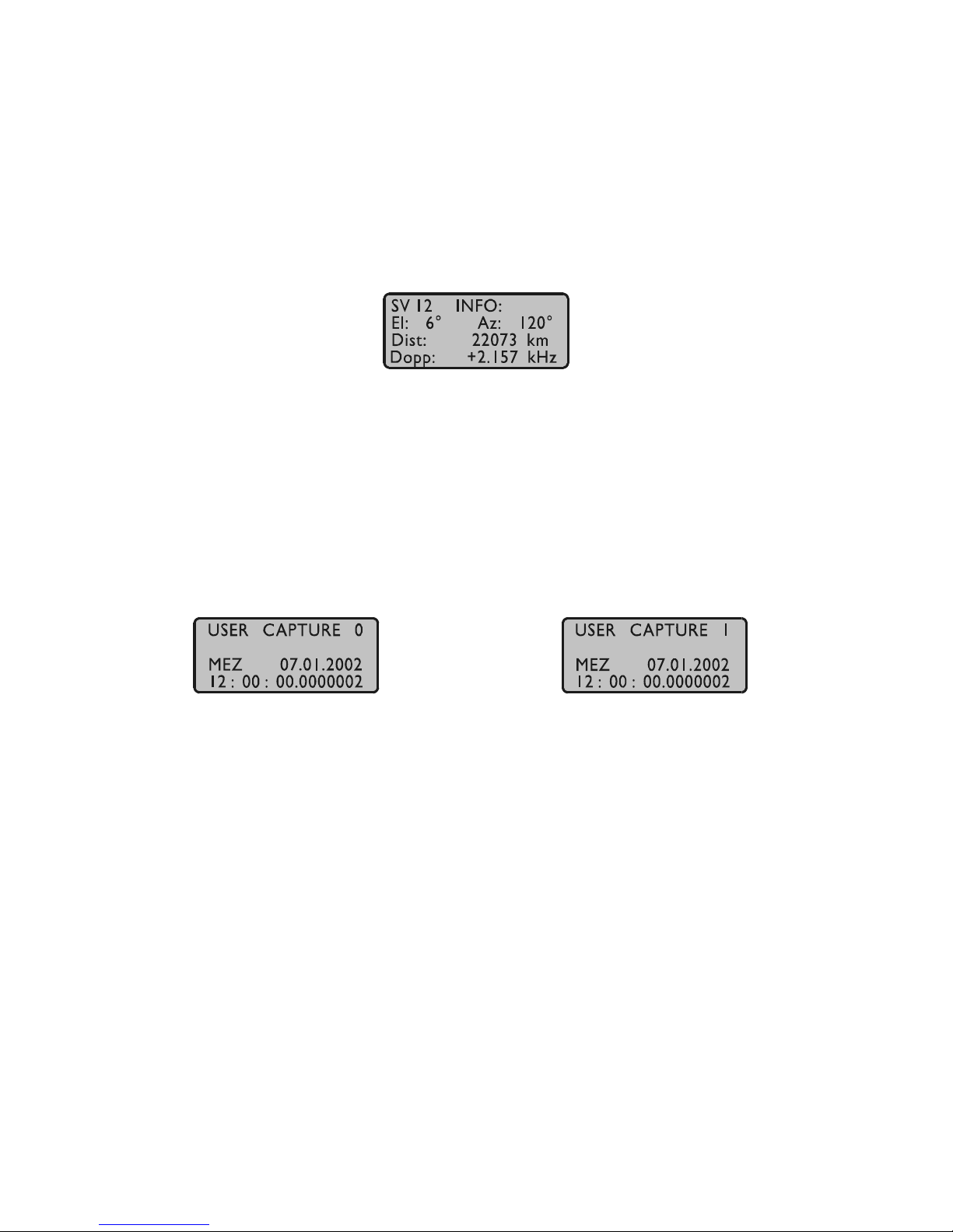
This menu gives information on the currently selected satellite (SV). The satellite´s ID
number, its elevation, azimuth and distance from the receiver position reflect the
satellite´s position in the sky whereas the doppler shows whether the satellite is
coming up from the horizon (doppler positive) or going down to the horizon (doppler
negative). All satellites in view can be monitored by using the NEXT key.
Menu USER CAPTURE
The time of the last recent capture event is displayed in this menu. The time zone
depends on the parameters entered in the setup menu (see below). The NEXT key lets
the display toggle between the two capture channels. If an error message ("Cap.
Overrun" or "Cap. Buffer Full") is displayed in the second line it can be acknowledged
pressing the CLR/ACK key.
Menu SETUP
From this menu, several topics can be selected which let the user edit parameters or
force special modes of operation. A specific topic can be selected using the NEXT
key. Depending on the current topic, pressing the CLR/ACK key either enters edit
mode with the selected set of parameters or switches to the selected mode of operation
(after the user has acknowledged his decision). Once edit mode has been entered, the
NEXT key lets the cursor move to the digit or letter to be edited whereas the INC key
increments the digit or letter under the cursor. If changes have been made, the CLR/
ACK key must be pressed in order to save those changes in the battery buffered
memory, otherwise all changes are discarded when the user presses the MENU key in
order to return to the SETUP display.
Page 21
21
SETUP FREQUENCY OUTPUT
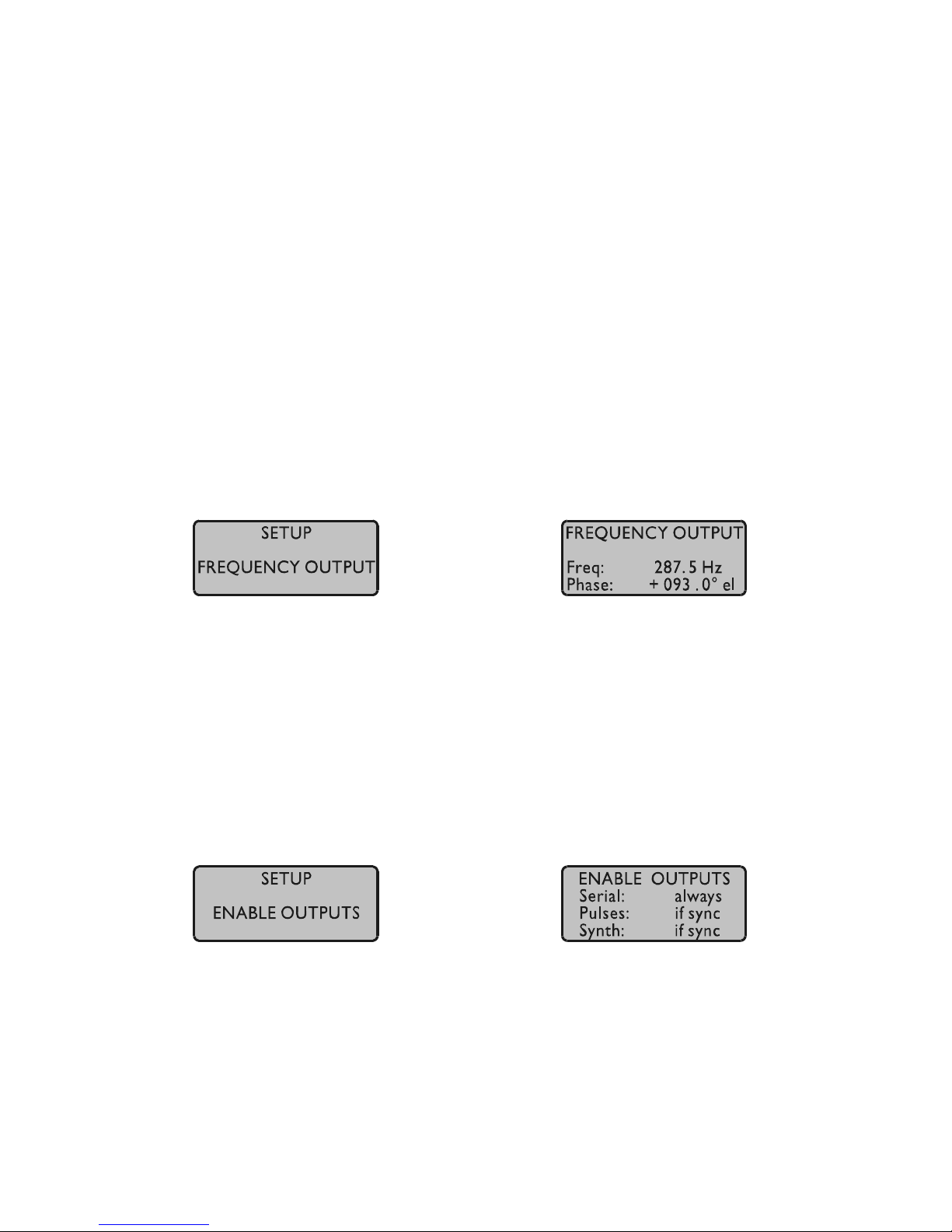
This setup menu lets the user edit the frequency and phase to be generated by the onboard synthesizer. Frequencies from 1/3Hz up to 10MHz can be entered using four
digits and a range. The range can be selected if the INC key is pressed while the cursor
is positioned on the frequency´s units string. If the least significant range has been
selected valid fractions of the frequency are .0, .1 (displayed as 1/8), .2 (displayed as
1/4), .3 (displayed as 1/3), .5 and .6 (displayed as 2/3). Selection of 1/3 or 2/3 means
real 1/3 or 2/3 Hz, not 0.33 or 0.66. If other fractions than those listed above are
entered, an error message "(inval. frac.)" is displayed. In the upper ranges any fraction
can be entered. If frequency is set to 0 the synthesizer is disabled.
The last line of the display lets the user enter the phase of the generated frequency
from -360° to +360° with a resolution of 0.1°. Increasing the phase lets the signal
come out later. Phase affects frequencies less than 10.00 kHz only, if a higher
frequency is selected a message "(phase ignored)" informs the user that the phase
value is ignored. The synthesizer is re-initialized with the parameters on the display if
the CLR/ACK key is pressed.
SETUP ENABLE OUTPUTS
This menu lets the user configure at which time after power up the serial ports, pulse
outputs, and frequency synthesizer output are to be enabled. Outputs which are shown
to be enabled always will be enabled immediately after power-up. Outputs which are
shown to be enabled if sync will be enabled after the receiver has decoded the signals
from the satellites and has checked or corrected its on-board clock. The default setting
for all outputs is if sync.
Page 22
22
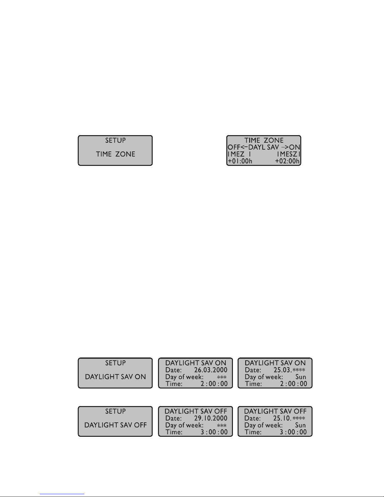
SETUP TIME ZONE
This menu lets the user enter the names of the local time zone with daylight saving
disabled and enabled, together with the zones´ time offsets from UTC. The left part of
the display shows the zone and offset if daylight saving is off whereas the right part
shows name and offset if daylight saving is on. These parameters are used to convert
UTC to local time, e.g. MEZ = UTC + 1h and MESZ = UTC + 2h for central europe.
The range of date daylight saving comes in effect can be entered using the next two
topics of the setup menu.
SETUP DAYLIGHT SAV ON/OFF
The two topics let the user enter the range of date for daylight saving to be in effect.
Concerning parameter input both topics are handled identically, so they are described
together in this chapter. Beginning and ending of daylight saving may either be
defined by exact dates for a single year or using an algorithm which allows the
receiver to recompute the effective dates year by year. The figures below show how to
enter parameters in both cases. If the number of the year is displayed as wildcards
(´*´), a day-of-week must be specified. Then, starting from the configured date,
daylight saving changes the first day which matches the configured day-of-week. In
the figure below March 25, 2000 is a Saturday, so the next Sunday is March 26, 2000.
All changeover rules for the daylight saving like "the first/the second/the second to
last/the last Sunday/Monday etc. in the x-th month," can be described by the used
format "first specified day-of-week after a defined date".
If the number of the year is not displayed as wildcards the complete date exactly
determines the day daylight saving has to change (March 28, 1999 in the figures
below), so the day-of-week doesn´t need to be specified and therefore is displayed as
wildcards.
changeover date for changeover the last
a single year Sunday in March/October
each year
Page 23
23
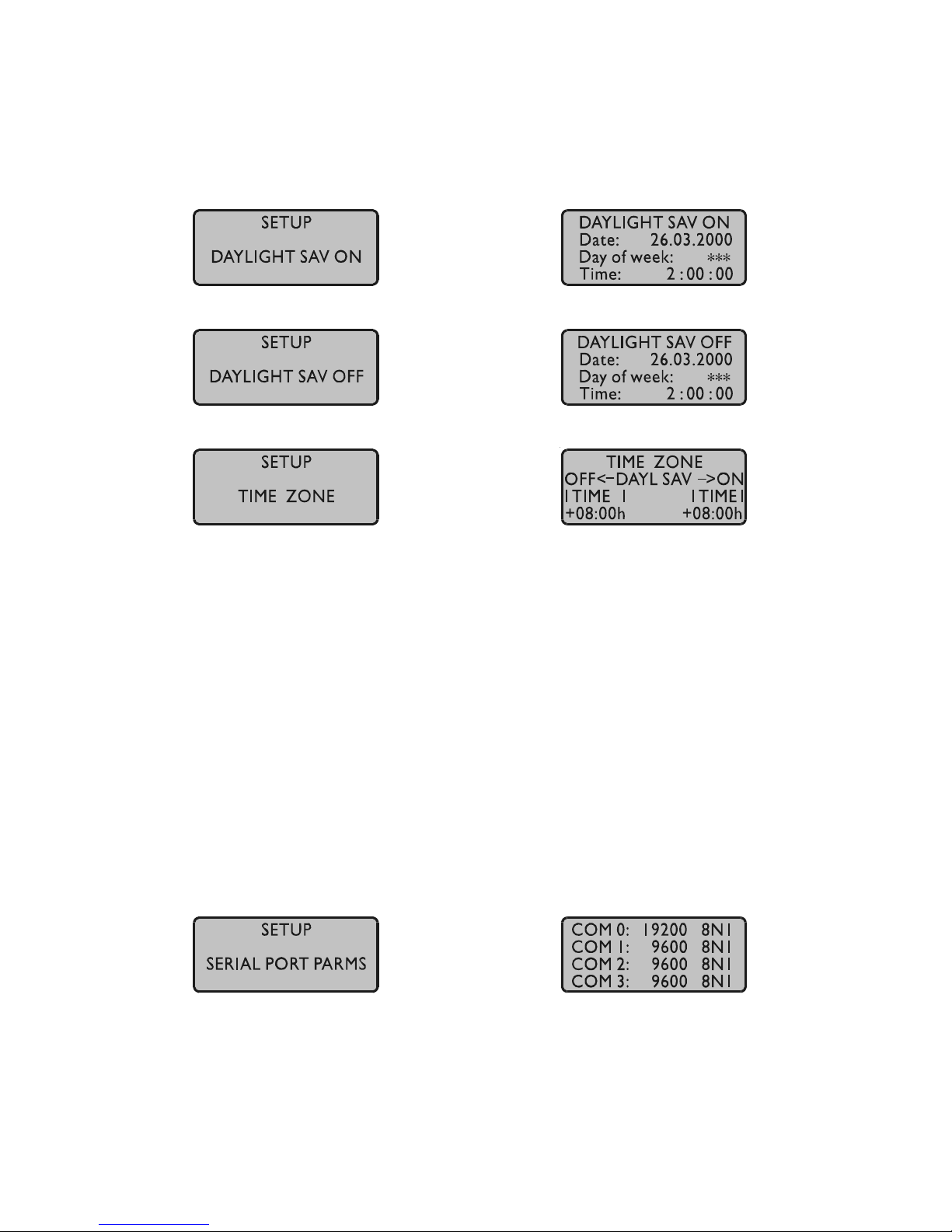
If no changeover in daylight saving is wanted, an identical date and time must be
configured in both of the submenus (see fig. below). In addition identical offsets for
DAYLIGHT SAV ON/OFF should be configured in the submenu TIMEZONE.
(Example for a region without daylight saving time and with a local time offset of
+8 hours to UTC.)
SETUP SERIAL PORT PARM
Using this topic the user can enter transmission speed and framing of each serial port.
Default parameters are:
COM0: 19200 baud, 8N1 COM2: 9600 baud, 8N1
COM1: 9600 baud, 8N1 COM3: 9600 baud, 8N1
Annotation: Even if one of the setup functions “INIT USER PARMS” or “Resetting
Factory Defaults” is executed, the serial port parameters are reset to
default values only if invalid parameters have been configured.
Page 24
24
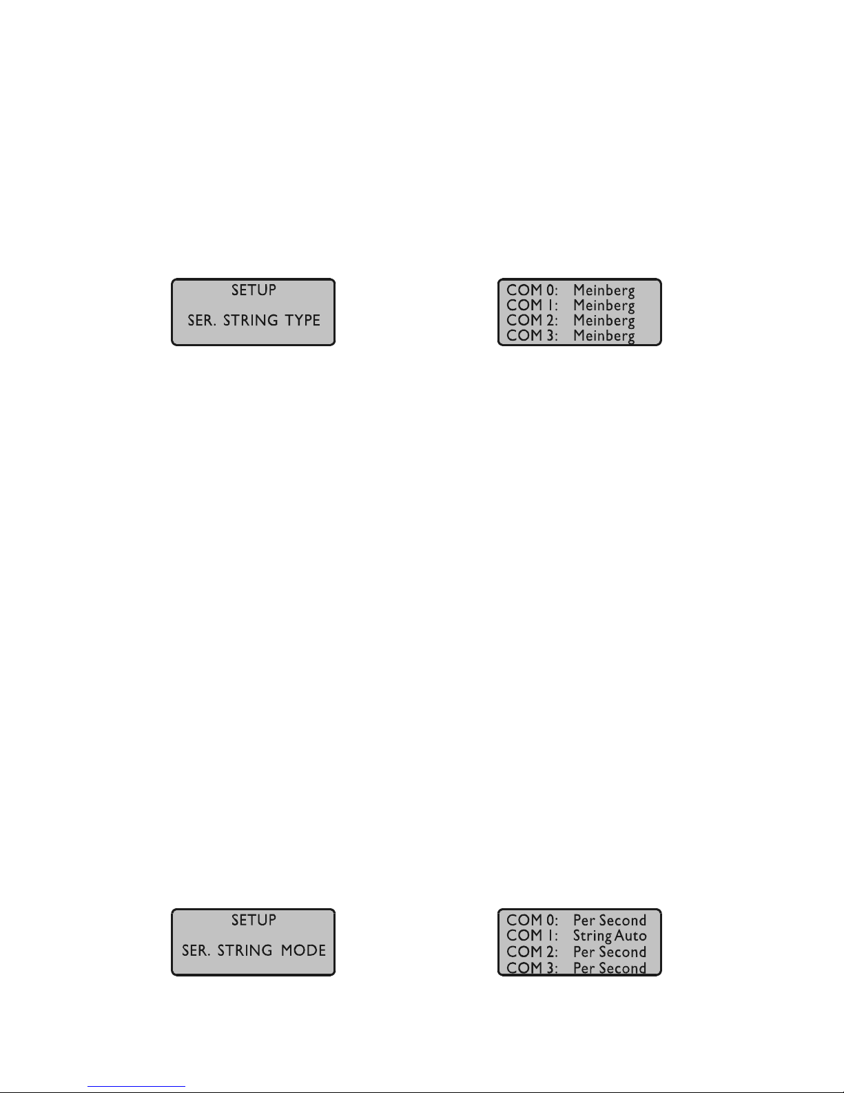
SETUP SERIAL STRING TYPE
This topic is used to select one of several different types of serial time strings or the
capture string for each serial port. Default parameters are:
COM0: Meinberg COM2: Meinberg
COM1: Capture COM3: Meinberg
The following time strings can be selected:
- Meinberg Standard String
- GPS167 Capture String
- SAT String
- UNI-Erlangen String
- NMEA String (RMC)
- SPA String
- Computime String
Other technical details are described at the end of this manual.
SETUP SERIAL STRING MODE
This menu lets the user select the serial ports´ mode of operation. The possible modes
depend on the selected output string. If a time string is selected it can be sent
automatically "Per Second", "Per Minute" or only "On Request" (sending an ASCII
"?" to the clock). If the capture string is selected it can be sent automatically when a
trigger event occurs ("String Auto") or only "On Request" (sending an ASCII "?" to
the clock). If capture message "On Request" is selected it is the user´s responsibility to
read out the capture buffer by sending an ASCII "?" to COMx or by the binary
protocol via COM0 in order to avoid a buffer-overrun and the loss of new trigger
events.
Page 25
25
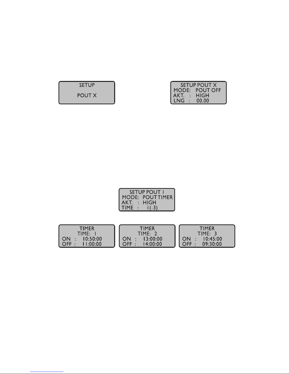
SETUP POUT X (optional)
This menu is used for configuration of the pulse outputs. There are three pulse outputs
available (POUT 1-3).
Mode
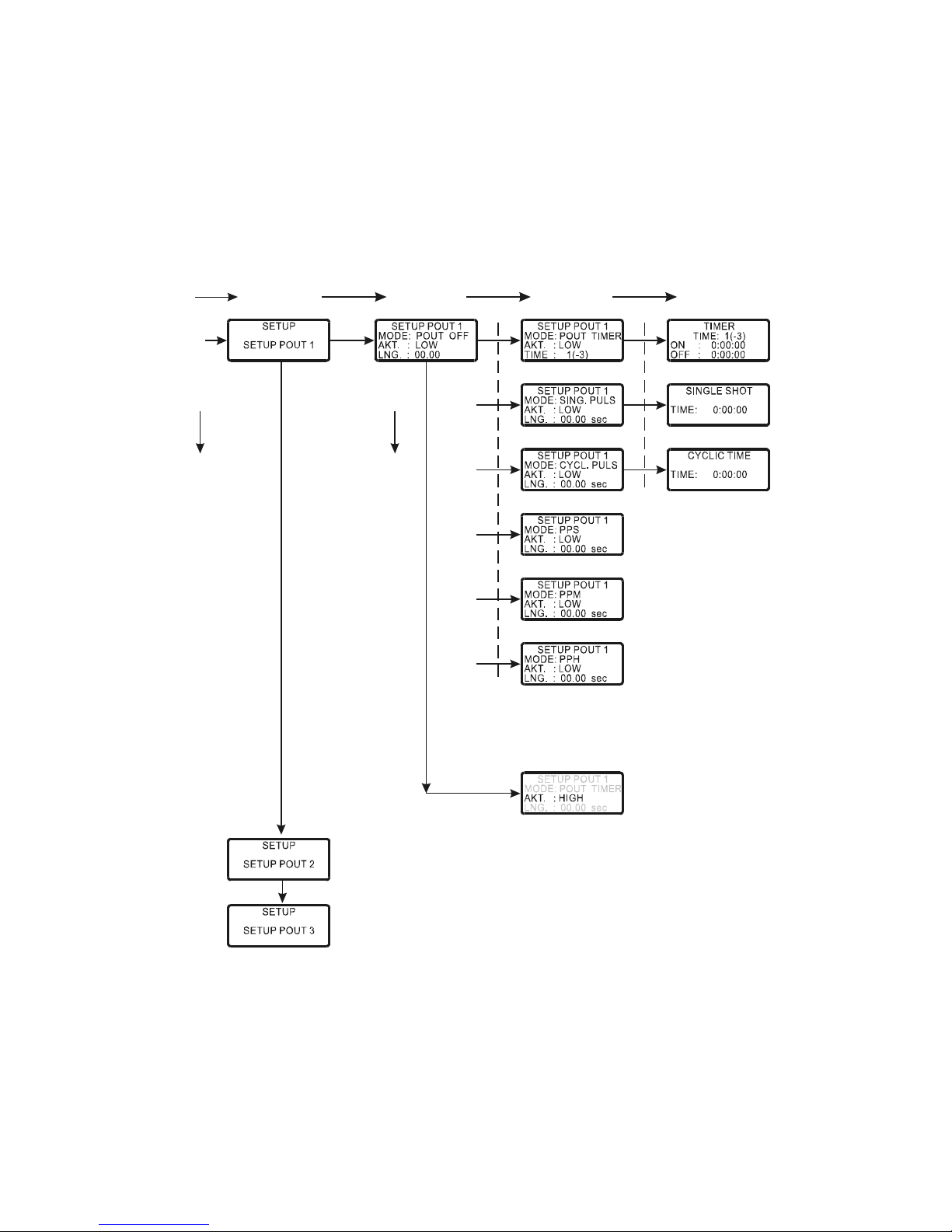
This field selects the mode of operation of an output. Possible modes are POUT OFF,
POUT TIMER, SINGLE PULSE, CYCLIC PULSE, PPS, PPM and PPH.
Timer mode
If Timer mode is selected, a window as shown above is displayed. The switching plan
is assigned per day. Three turn-on and turn-off times are programmable for each
output. If a switching time has to be configured, only the turn-on and turn-off time
must be programmed. Thus the example shows switching times from 10.50 to 11.00,
13.00 to 14.00 and 23.45 to 23.50. A turn-off time earlier than the turn-off time would
cause the output to be enabled over midnight. For example a program 'On Time'
10.45.00, 'Off Time' 9.30.00 would cause an active ouput from 10.45 to 9.30 (the
next day!). If one or more of the three switching times are unused just enter the same
time into the fields 'On Time' and 'Off Time'. In this case the switch time does not
affect the output.
Page 26
26
Single Pulse
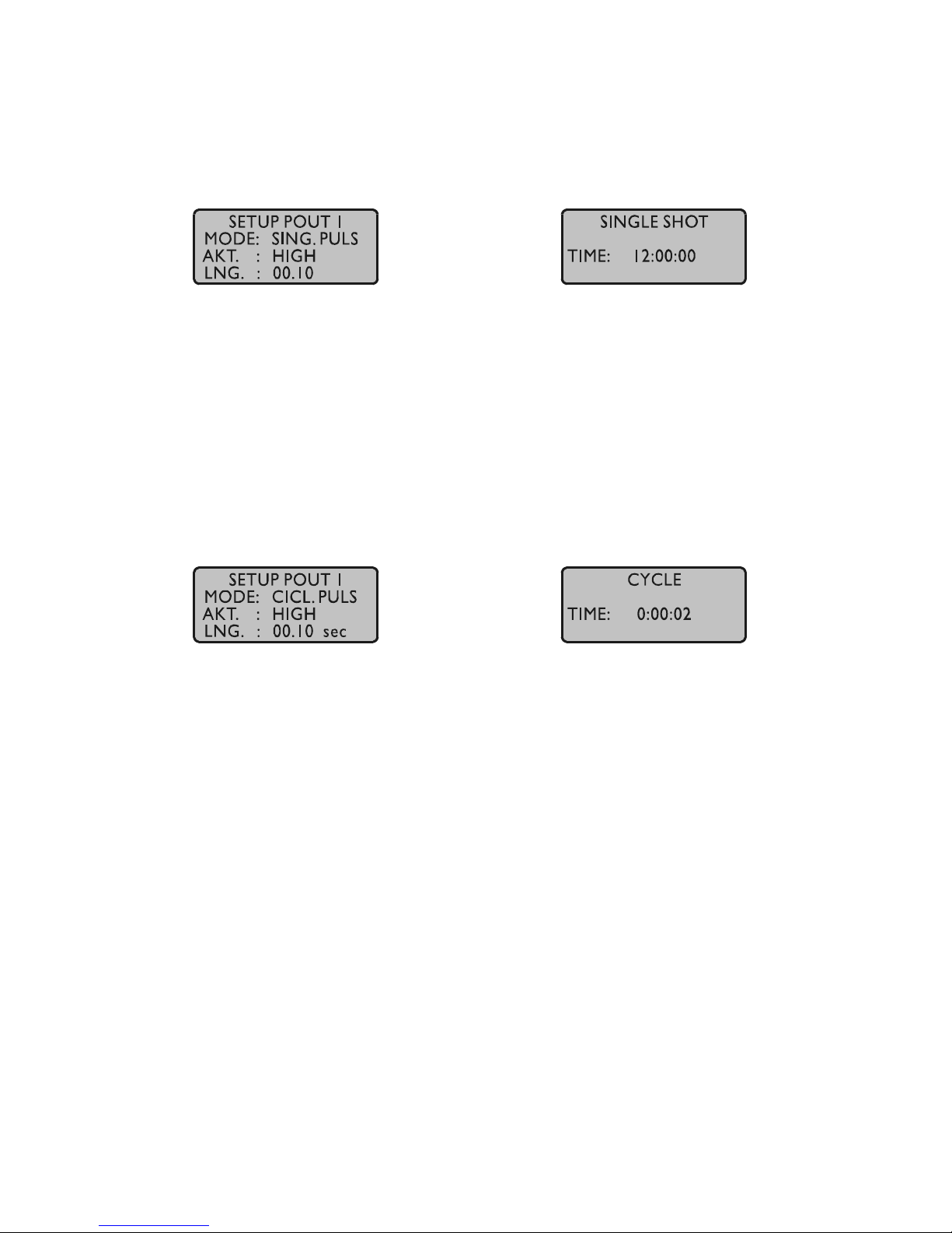
Selecting Single Pulse generates a single pulse of defined length once per day.
You can enter the time when the pulse is generated in the field 'Single Shot Time'.
The value in field 'Length' determines the pulse duration. A pulse duration from 10
msec to 10 sec in steps of 10 msec can be selected.
The example shows a single pulse at 12:00 every day with a duration of 100 ms.
Cyclic mode
Cyclic mode is used for generating periodically repeated pulses.
The value in field 'Cycle Time' determines the time between two consecutive pulses
(2 sec in example above). This cycle time must be entered as hours, minutes and
seconds. The pulse train is synchronized at 0:00 o'clock local time, so the first pulse of
a day always occurs at midnight. A cycle time of 2 seconds for example, would cause
pulses at 0:00:00, 0:00:02, 0:00:04 etc. Basically it is possible to enter any cycle time
between 0 and 24 hours, however only a cycle times that causes a constant distance
between all consecutive pulses make sense. For example a cycle time of 1 hour 45
minutes would generate a pulse every 6300 seconds (starting from 0 o'clock). The
duration between the last pulse of a day and the first pulse of the next day (0:00:00
o'clock) would only be 4500 sec.
PPS, PPM, PPH Modes
These modes generate pulses of defined length once per second, once per minute or
one per hour. 'Single Shot Time' determines the pulse duration (10 msec...10 sec).
The respective output remains in active state, when selecting a pulse duration longer
than 990ms in pulse per sec mode.
Page 27
27
Menu Quick Reference for progr. Pulse
CLR/ACK CLR/ACKINC
MODE
AKTIV
MENU
NEXT NEXT
Page 28
28
SETUP IRIG SETTINGS (optional)
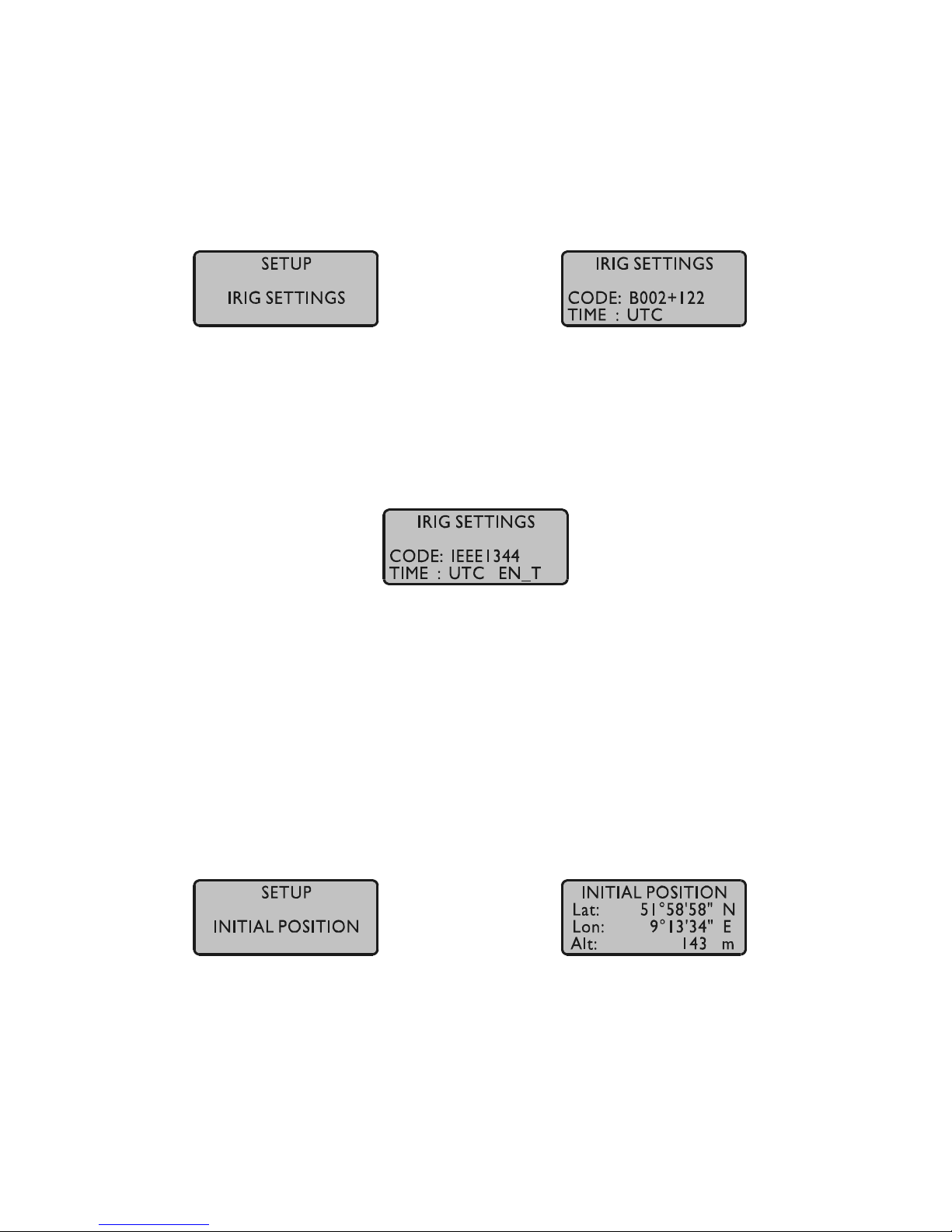
This menu lets the user select the timecodes to be generated by GPS167. Most IRIG
codes do not carry any time zone information, hence UTC is selected for output by
default. If desired, the clock´s local time can be output by selecting "TIME: LOCAL".
The IEEE1344 has a so called TFOM (time figure of merit) segment that carries an
information on the synchronization state of the radio clock.
Whenever the selected timecode carries TFOM, it can be blanked by selecting "disable
TFOM", This feature can be helpful for testing when the connected IRIG reader
evaluates TFOM.
SETUP INITIAL POSITION
When the receiver is primarily installed at a new location far away from the last
position saved in the receiver´s memory the satellites in view and their dopplers will
differ so much from those expected due to the wrong position that GPS167 has to scan
for satellites in Warm Boot mode. Making the new approximately known position
available to the receiver can avoid Warm Boot and speed up installation.
Page 29
29
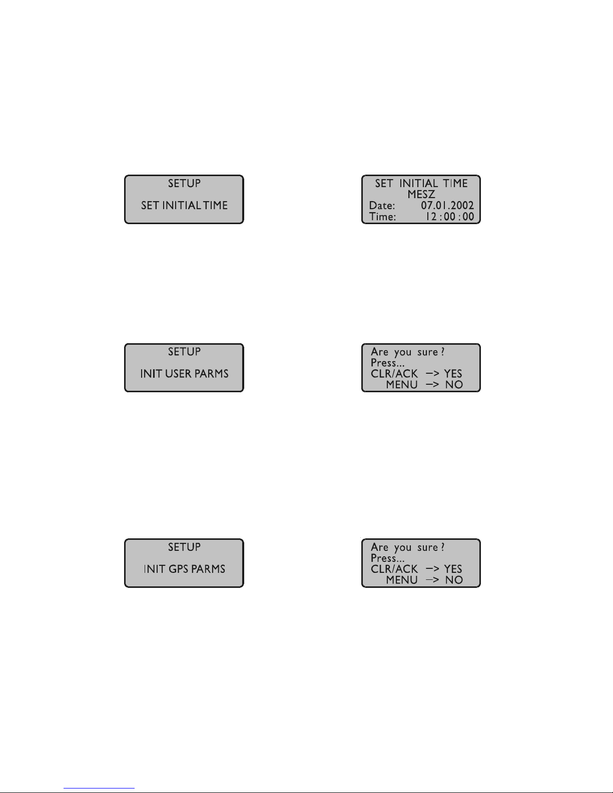
SETUP INITIAL TIME
If the receiver´s on-board real time clock keeps a wrong time the receiver is unable to
compute the satellites´ correct elevation angles and dopplers. This submenu enables
the user to change the receiver´s system time for initialization. After the receiver has
locked, its real time clock will be adjusted using the information from the satellites.
INIT USER PARMS
This menu lets the user set all parameters back to the default settings. The user has to
acknowledge this menu again before the initialisation starts.
INIT GPS PARMS
This menu lets the user initialize all GPS datas, i.e. all saved satellite datas will be
cleared. The user has to acknowledge this menu again before the initialisation starts.
The system starts operating in the COLD BOOT mode and seeks for a satellite to read
its actual parameters.
Page 30
30
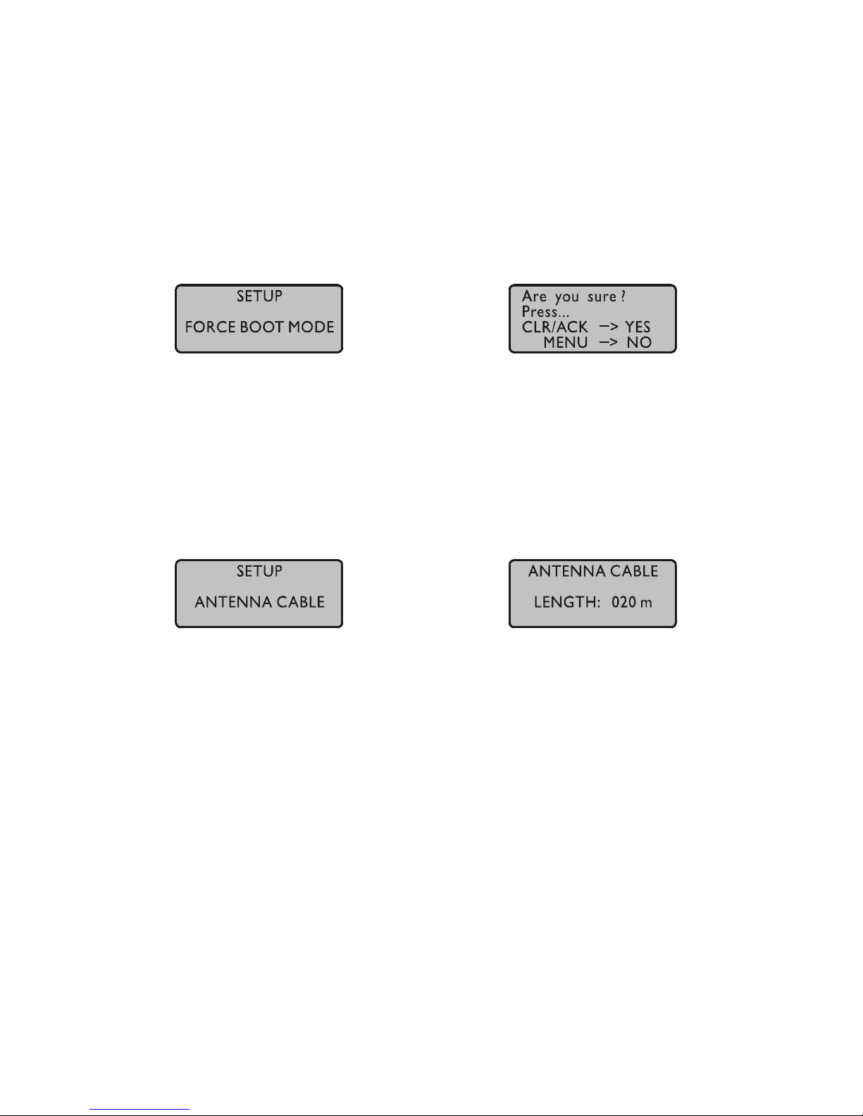
FORCE BOOT MODE
This menu lets the user force the receiver into the Boot Mode. This may be necessary
when the satellite datas in the memory are too old or the receiver position has changed
by some hundred kilometers since last operation. Syncronisation time may be reduced
significant. If there are valid satellite datas in the memory the system starts in the
WARM BOOT mode, otherwise the system changes into COLD BOOT to read new
datas.
ANTENNA CABLE
This menu asks the user to enter the length of the antenna cable. The received time
frame is delayed by approx. 5ns per meter antenna cable. The receiver is able to
compensate this delay if the exact cable length is given. The default value is 20m. The
maximum value that can be entered is 500m (only with low loss cable).
Page 31

31
Resetting Factory Defaults
If both the NEXT key and the INC key on the front panel are pressed while the system
is powered up the battery buffered memory is cleared and user definable parameters
are reset to factory defaults. The key should be held until the root menu is displayed on
LCD. Due to the fact that the satellites´parameters have been cleared, the system
comes up in COLD BOOT mode.
Firmware Updates
Whenever the on-board software must be upgraded or modified, the new firmware can
be downloaded to the internal flash memory via the serial port COM0. There is no
need to open the metal case and insert a new EPROM.
If the MENU key on the front panel is pressed while the system is powered up, a
bootstrap-loader is actived and waits for instructions from the serial port COM0. The
new firmware can be sent to GPS167 from any standard PC with serial interface. A
loader program will be shipped together with the file containing the image of the new
firmware.
The contents of the program memory will not be modified until the loader program
has sent the command to erase the flash memory. So if the MENU key is pressed
unintentionally while the system is powered up, the firmware will not be changed
accidentially. After the next power-up, the system will be ready to operate again.
Page 32
32
Skilled/Service-Personnel only: Replacing the Lithium Battery
The life time of the lithium battery on the board is at least 10 years. If the need arises
to replace the battery, the following should be noted:
ATTENTION!
Danger of explosion in case of inadequate replacement of
the lithium battery. Only identical batteries or batteries
recommended by the manufacturer must be used for
replacement. The waste battery must be disposed as pro-
posed by the manufacturer of the battery.
CE Label
This device conforms to the directive 89/336/EWG on the
approximation of the laws of the Member States of the European
Community relating to electromagnetc compatibility.
Page 33

33
Technical Specifications GPS167
RECEIVER: 6 channel C/A code receiver with external
antenna/converter unit
ANTENNA: Antenna/converter unit with remote power supply
refer to chapter "Technical Specifications GPS167 Antenna"
ANTENNA
INPUT: antenna circuit DC-insulated; dielectric strength: 1000V
Length of cable: refer to chapter "Mounting the Antenna"
LC DISPLAY: 4x16 character, menu selectable by push buttons
TIME TO SYNCHRONIZATION: one minute with known receiver position and valid almanac
12 minutes if invalid battery buffered memory
PULSE
OUTPUTS: change of second (P_SEC, TTL level)
change of minute (P_MIN, TTL level)
ACCURACY OF
PULSES: after synchronization and 20 minutes of operation
TCXO HQ/OCXO LQ : besser als ±250 nsec
OCXO MQ/OCXO HQ : besser als ±100 nsec
better than ±2 µsec during the first 20 minutes of operation
FREQUENCY
OUTPUTS: 10 MHz, 1 MHz, 100 kHz (TTL level)
Page 34

34
SYNTHESIZER: 1/8 Hz up to 10 MHz
ACCURACY OF
SYNTHESIZER: base accuracy depends on system accuracy
1/8 Hz to 10 kHz Phase syncron with pulse output P_SEC
10 kHz to 10 MHz frequency deviation < 0.0047 Hz
SYNTHESIZER
OUTPUTS: F_SYNTH: TTL level
F_SYNTH_OD: open drain
drain voltage: < 100 V
sink current to GND: < 100 mA
dissipation power at 25°C: < 360 mW
F_SYNTH_SIN sine-wave
output voltage: 1.5 V eff.
output impedance: 200 Ohm
TIME_SYN
OUTPUT: TTL HIGH level if synchronized
SERIAL PORTS: max. 4 asynchronous serial ports (RS-232)
Baud Rate: 300 up to 19200
Framing: 7N2, 7E1, 7E2, 8N1, 8N2, 8E1
default setting: COM0: 19200, 8N1
COM1: 9600, 8N1
COM2: 9600, 8N1
COM3: 9600, 8N1
Annotation: Even if one of the setup functions “INIT USER
PARMS” or “Resetting Factory Defaults” is
executed, the serial port parameters are reset
to default values only if invalid parameters
have been configured.
TIME CAPTURE
INPUTS: triggered on falling TTL slope
Interval of events: 1.5msec min.
Resolution: 100ns
Page 35
35
POWER
REQUIREMENTS: 5V ± 5%, max. @1100mA (see oscilatorspecifikations)
PHYSICAL
DIMENSION: 19" module in a closed 112mm high x 102mm wide closed
aluminium case
FRONT PANEL: 3U / 21HP (128mm high x 107mm wide), Aluminium
REAR EDGE
CONNECTOR: according to DIN 41612, type C 64, rows a+c (male)
RF CONNECTOR: coaxial BNC
AMBIENT
TEMPERATURE: 0 ... 50°C
HUMIDITY: 85% max.
Oscillator specifications
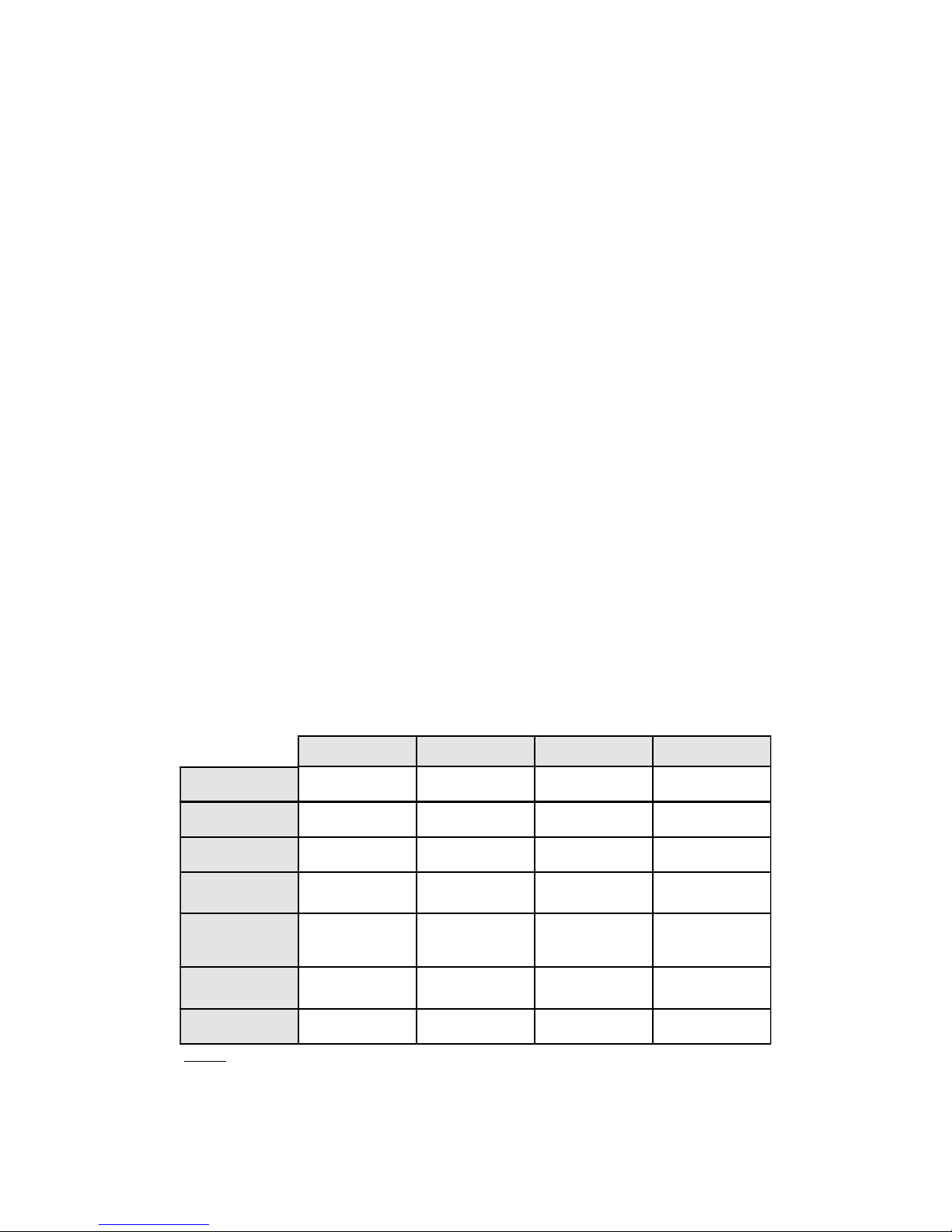
TCXO OCXO LQ OCXO M Q OCXO HQ
short term stability
τ = 1 sec
2 * 10 E-9 1 * 10 E-9 2 * 10 E-10 1 * 10 E-11
accurracy free run
one day
+/- 1 * 10 E-7
+/- 1 Hz (Note 1)
+/- 2 * 10 E-8
+/- 0.2 Hz (Note 1)
+/- 1,5 * 10 E-9
+/- 15 mHz (Note 1)
+/- 5 * 10 E-10
+/- 5 mHz (Note 1)
accurracy free run
one year
+/- 1 * 10 E-6
+/- 10 Hz (Note 1)
+/- 4 * 10 E-7
+/- 4 Hz (Note 1)
+/- 1 * 10 E-7
+/- 1 Hz (Note 1)
+/- 5 * 10 E-8
+/- 0.5 Hz (Note 1)
accurracy GPS-synchronous
averaged 24 h
+/- 1 * 10 E-11 +/- 1 * 10 E-11 +/- 5 * 10 E-12 +/- 1 * 10 E-12
phase noise
1 Hz
10 Hz
100 Hz
1 kHz
-60 dBc/Hz
-90 dBc/Hz
-120 dBc/Hz
-130 dBc/Hz
1 Hz
10 Hz
100 Hz
1 kHz
-60 dBc/Hz
-90 dBc/Hz
-120 dBc/Hz
-130 dBc/Hz
1 Hz
10 Hz
100 Hz
1 kHz
-75 dBc/Hz
-110 dBc/Hz
-130 dBc/Hz
-140 dBc/Hz
1 Hz
10 Hz
100 Hz
1 kHz
-95 dBc/Hz
-125 dBc/Hz
-145 dBc/Hz
-155 dBc/Hz
power supply at 25°C
steady state
warm up
+5V / 20 mA
N/A
+5V / 160 mA
+5V / 380 mA
+5V / 90 mA
+5V / 330 mA
+5V / 160 mA
+5V / 600 mA
temperature dependant drift
free run
+/- 1 * 10 E-6
(-20...70°C)
+/- 2 * 10 E-7
(0...60°C)
+/- 5 * 10 E-8
(-20...70°C)
+/- 1 * 10 E-8
(5...70°C)
Note 1:
The accurracy in Hertz is based on the standard frequency of 10 MHz. For example:
Accurracy of TCXO (free run one day) is +/- 1 * 10 E-7 * 10 MHz = +/- 1 Hz
Page 36
36
Technical Specifications GPS167 Antenna
ANTENNA: dielectrical patch antenna, 25 x 25mm
receive frequency: 1575.42 MHz
bandwidth: 9 MHz
CONVERTER: local oscillator to converter frequency: 10 MHz
first IF frequency: 35.4 MHz
POWER
REQUIREMENTS: 12V ... 18V, @ 100mA (provided via antenna cable)
CONNECTOR: coax type N, female
AMBIENT
TEMPERATURE: -40 ... +65°C
HOUSING: ABS plastic case for outdoor installation (IP56)
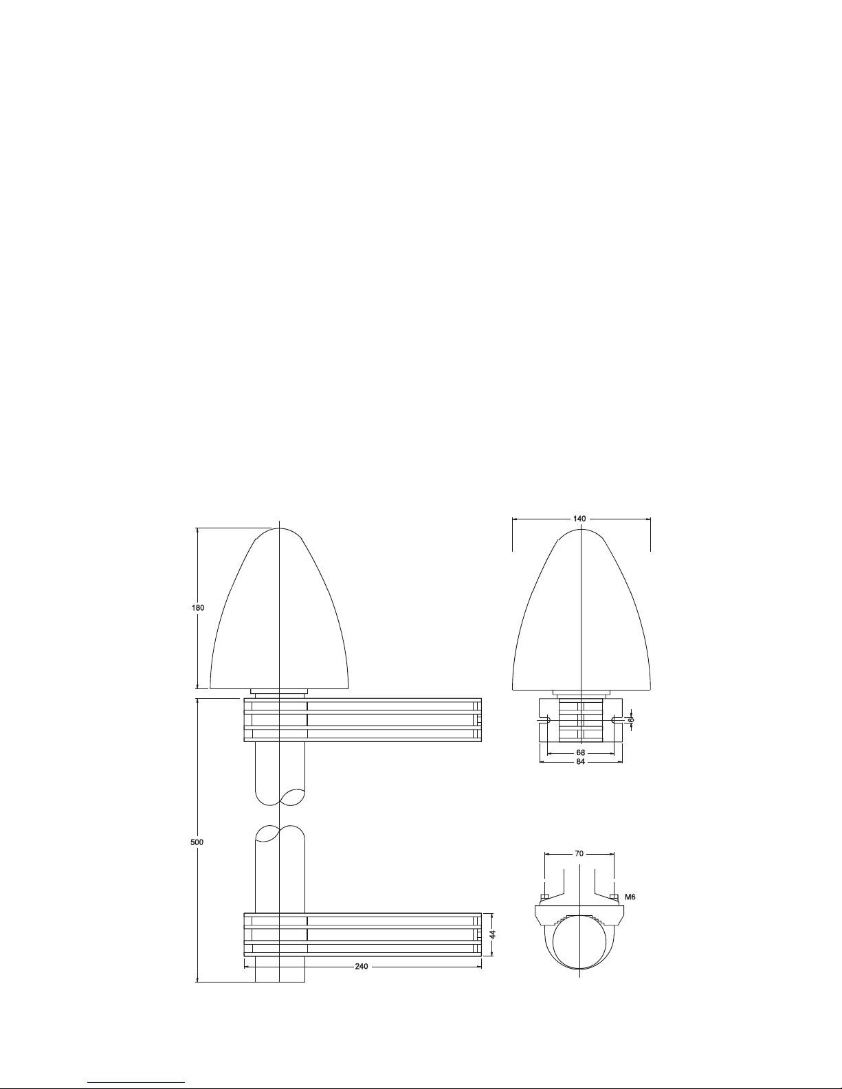
PHYSICAL
DIMENSION:
Page 37

37
Time Strings
Format of the Meinberg Standard Time String
The Meinberg Standard Time String is a sequence of 32 ASCII characters starting
with the STX (start-of-text) character and ending with the ETX (end-of-text) character. The format is:
<STX>D:dd.mm.yy;T:w;U:hh.mm.ss;uvxy<ETX>
The letters printed in italics are replaced by ASCII numbers whereas the other
characters are part of the time string. The groups of characters as defined below:
<STX> Start-Of-Text, ASCII Code 02h
sending with one bit occuracy at change of second
dd.mm.yy the current date:
dd day of month (01..31)
mm month (01..12)
yy year of the century (00..99)
w the day of the week (1..7, 1 = Monday)
hh.mm.ss the current time:
hh hours (00..23)
mm minutes (00..59)
ss seconds (00..59, or 60 while leap second)
uv clock status characters (depending on clock type):
u: ‘#’ GPS: clock is running free (without exact synchr.)
PZF: time frame not synchronized
DCF77: clock has not synchronized after reset
‘ ‘ (space, 20h)
GPS: clock is synchronous (base accuracy is reached)
PZF: time frame is synchronized
DCF77: clock has synchronized after reset
v: ‘*’ GPS: receiver has not checked its position
PZF/DCF77: clock currently runs on XTAL
‘ ‘ (space, 20h)
GPS: receiver has determined its position
PZF/DCF77: clock is syncronized with transmitter
x time zone indicator:
‘U’ UTC Universal Time Coordinated, formerly GMT
‘ ‘ MEZ European Standard Time, daylight saving disabled
‘S’ MESZ European Summertime, daylight saving enabled
y anouncement of discontinuity of time, enabled during last hour
before discontinuity comes in effect:
‘!’ announcement of start or end of daylight saving time
‘A’ announcement of leap second insertion
‘ ‘ (space, 20h) nothing announced
<ETX> End-Of-Text, ASCII Code 03h
Page 38

Format of the Meinberg Capture String
The Meinberg Capture String is a sequence of 31 ASCII characters terminated by a
CR/LF (Carriage Return/Line Feed) combination. The format is:
CHx_tt.mm.jj_hh:mm:ss.fffffff<CR><LF>
The letters printed in italics are replaced by ASCII numbers whereas the other
characters are part of the time string. The groups of characters as defined below:
x 0 or 1 corresponding on the number of the capture input
_ ASCII space 20h
dd.mm.yy the capture date:
dd day of month (01..31)
mm month (01..12)
yy year of the century (00..99)
hh:mm:ss.fffffff the capture time:
hh hours (00..23)
mm minutes (00..59)
ss seconds (00..59, or 60 while leap second)
fffffff fractions of second, 7 digits
<CR> Carriage Return, ASCII Code 0Dh
<LF> Line Feed, ASCII Code 0Ah
Page 39

Format of the SAT Time String
The SAT Time String is a sequence of 29 ASCII characters starting with the STX
(start-of-text) character and ending with the ETX (end-of-text) character. The format
is:
<STX>dd.mm.yy/w/hh:mm:ssxxxxuv<ETX>
The letters printed in italics are replaced by ASCII numbers whereas the other
characters are part of the time string. The groups of characters as defined below:
<STX> Start-Of-Text, ASCII Code 02h
sending with one bit occuracy at change of second
dd.mm.yy the current date:
dd day of month (01..31)
mm month (01..12)
yy year of the century (00..99)
w the day of the week (1..7, 1 = Monday)
hh:mm:ss the current time:
hh hours (00..23)
mm minutes (00..59)
ss seconds (00..59, or 60 while leap second)
xxxx time zone indicator:
‘UTC‘ Universal Time Coordinated, formerly GMT
‘MEZ‘ European Standard Time, daylight saving disabled
‘MESZ’ European Summertime, daylight saving enabled
u clock status characters:
‘#’ clock has not synchronized after reset
‘ ‘ (space, 20h) clock has synchronized after reset
v anouncement of discontinuity of time, enabled during last hour
before discontinuity comes in effect:
‘!’ announcement of start or end of daylight saving time
‘ ‘ (space, 20h) nothing announced
<CR> Carriage Return, ASCII Code 0Dh
<LF> Line Feed, ASCII Code 0Ah
<ETX> End-Of-Text, ASCII Code 03h
Page 40

40
Format of the Uni Erlangen String (NTP)
The time string Uni Erlangen (NTP) of a GPS clock is a sequence of 66 ASCII
characters starting with the STX (start-of-text) character and ending with the ETX
(end-of-text) character. The format is:
<STX>tt.mm.jj; w; hh:mm:ss; voo:oo; acdfg i;bbb.bbbbn lll.lllle hhhhm<ETX>
The letters printed in italics are replaced by ASCII numbers whereas the other
characters are part of the time string. The groups of characters as defined below:
<STX> Start-Of-Text, ASCII Code 02h
sending with one bit occuracy at change of second
dd.mm.yy the current date:
dd day of month (01..31)
mm month (01..12)
yy year of the century (00..99)
w the day of the week (1..7, 1 = Monday)
hh.mm.ss the current time:
hh hours (00..23)
mm minutes (00..59)
ss seconds (00..59, or 60 while leap second)
v sign of the offset of local timezone related to UTC
oo:oo offset of local timezone related to UTC in hours and minutes
ac clock status characters:
a: ‘#’ clock has not synchronized after reset
‘ ‘ (space, 20h) clock has synchronized after reset
c: ‘*’ GPS receiver has not checked its position
‘ ‘ (space, 20h) GPS receiver has determined its position
d time zone indicator:
‘S’ MESZ European Summertime, daylight saving enabled
‘ ‘ MEZ European Standard Time, daylight saving disabled
f anouncement of discontinuity of time, enabled during last hour
before discontinuity comes in effect:
‘!’ announcement of start or end of daylight saving time
‘ ‘ (space, 20h) nothing announced
g anouncement of discontinuity of time, enabled during last hour
before discontinuity comes in effect:
‘A’ announcement of leap second insertion
‘ ‘ (space, 20h) nothing announced
Page 41

41
i leap second insertion
‘L’ leap second is actually inserted
(active only in 60th sec.)
‘ ‘ (space, 20h) no leap second is inserted
bbb.bbbb latitude of receiver position in degrees
leading signs are replaced by a space character (20h)
n latitude, the following characters are possible:
‘N’ north of equator
‘S’ south d. equator
lll.llll longitude of receiver position in degrees
leading signs are replaced by a space character (20h)
e longitude, the following characters are possible:
‘E’ east of Greenwich
‘W’ west of Greenwich
hhhh altitude above sea level in meters
leading signs are replaced by a space character (20h)
<ETX> End-Of-Text, ASCII Code 03h
Page 42

42
Format of the NMEA 0183 String (RMC)
The NMEA String is a sequence of 65 ASCII characters starting with the ‘$’ character
and ending with the characters CR (carriage return) and LF (line-feed). The format is:
$GPRMC,hhmmss.ss,A,bbbb.bb,n,lllll.ll,e,0.0,0.0,ddmmyy,0.0,a*hh<CR><LF>
The letters printed in italics are replaced by ASCII numbers or letters whereas the
other characters are part of the time string. The groups of characters as defined below:
$ Start character, ASCII Code 24h
sending with one bit occuracy at change of second
hhmmss.ss the current time:
hh hours (00..23)
mm minutes (00..59)
ss seconds (00..59, or 60 while leap second)
ss fractions of seconds (1/10 ; 1/100)
A Status (A = time data valid)
(V = time data not valid)
bbbb.bb latitude of receiver position in degrees
leading signs are replaced by a space character (20h)
n latitude, the following characters are possible:
‘N’ north of equator
‘S’ south d. equator
lllll.ll longitude of receiver position in degrees
leading signs are replaced by a space character (20h)
e longitude, the following characters are possible:
‘E’ east of Greenwich
‘W’ west of Greenwich
ddmmyy the current date:
dd day of month (01..31)
mm month (01..12)
yy year of the century (00..99)
a magnetic variation
hh checksum (EXOR over all characters except ‘$’ and ‘*’)
<CR> Carriage Return, ASCII Code 0Dh
<LF> Line Feed, ASCII Code 0Ah
Page 43

43
Format of the ABB SPA Time String
The ABB SPA Time String is a sequence of 32 ASCII characters starting with the
characters ">900WD" and ending with the <CR> (Carriage Return) character. The
format is:
>900WD:yy-mm-tt_hh.mm;ss.fff:cc<CR>
The letters printed in italics are replaced by ASCII numbers whereas the other
characters are part of the time string. The groups of characters as defined below:
yy-mm-tt the current date:
yy year of the century (00..99)
mm month (01..12)
dd day of month (01..31)
_ Space (ASCII code 20h)
hh.mm;ss.fff the current time:
hh hours (00..23)
mm minutes (00..59)
ss seconds (00..59, or 60 while leap second)
fff milliseconds (000..999)
cc Check sum. EXCLUSIVE-OR result of the previous characters,
displayed as a HEX byte (2 ASCII characters 0..9 or A..F)
<CR> Carriage Return, ASCII Code 0Dh
Page 44

44
Format of the Computime Time String
The Computime time string is a sequence of 24 ASCII characters starting with the T
character and ending with the LF (line feed, ASCII Code 0Ah) character. The format
is:
T:yy:mm:dd:ww:hh:mm:ss<CR><LF>
The letters printed in italics are replaced by ASCII numbers whereas the other
characters are part of the time string. The groups of characters as defined below:
T Start character
sending with one bit occuracy at change of second
yy:mm:dd the current date:
yy year of the century (00..99)
mm month (01..12)
dd day of month (01..31)
ww the day of the week (01..07, 01 = monday)
hh:mm:ss the current time:
hh hours (00..23)
mm minutes (00..59)
ss seconds (00..59, or 60 while leap second)
<CR> Carriage Return, ASCII Code 0Dh
<LF> Line Feed, ASCII Code 0Ah
Page 45
45
Timecode (optional)
Principle of Operation
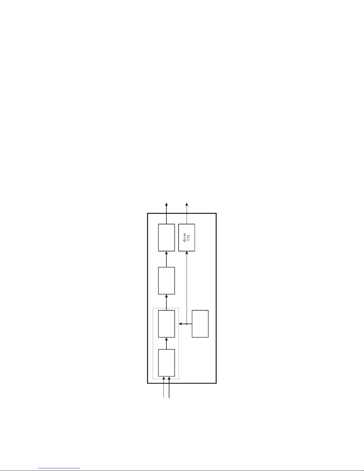
The Board GPS167 has been designed for the generation of IRIG, AFNOR and
IEEE1344 standard time codes. Apart from the digitally generated amplitude-modulated code, it also provides the unmodulated DC-Level shift code. The modulated sine
wave carrier and the board´s internal time pattern are derived from the radio clock´s
disciplined oscillator.
Block Diagram Timecode
microcontroller
modulator
EPLD
D/A conve rter
driver
50 unbalanced
Ω
digital
sinewave
generator
timecode
10 MHz
modula ted timecod e
unmodulated timecodes
high- and low-active
PPS
Page 46
46
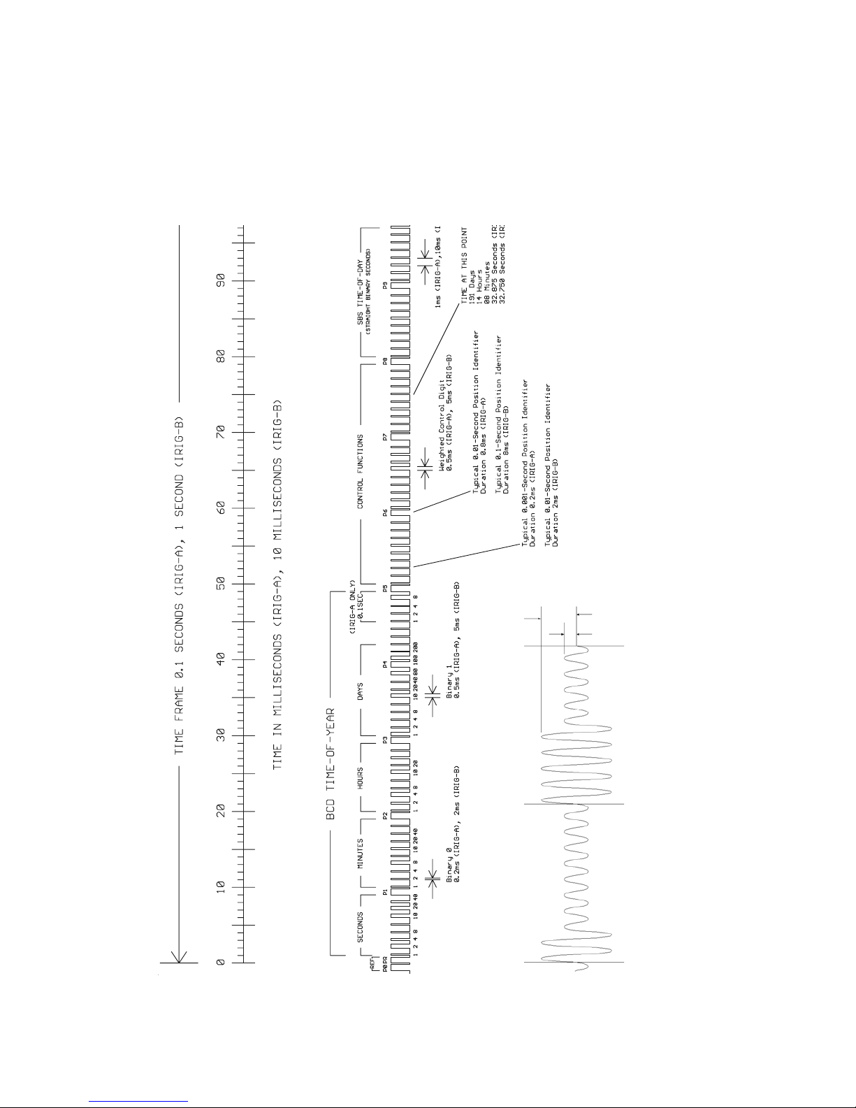
IRIG Standard Format
x 3x
TYPICAL MODULATED CARRIER IRIG-A : 10000 Hz
IRIB-B : 1000 Hz
binary 0 binary 1
Page 47
47
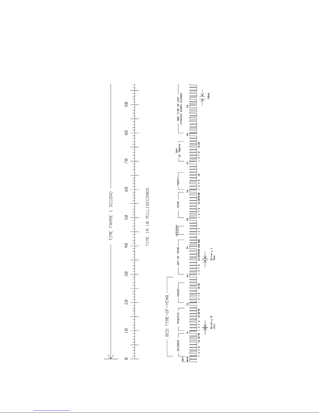
AFNOR Standard Format
Page 48
48
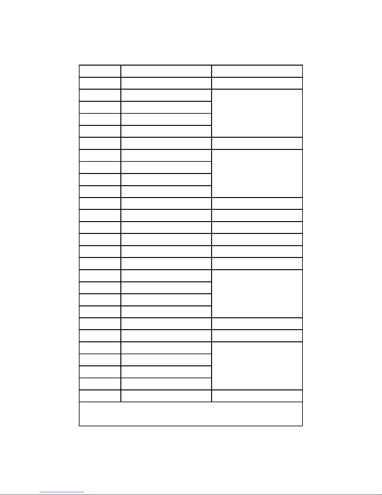
Assignment of CF Segment in IEEE1344 mode
Bit No. D esignation De scription
49
Position Identifier P5
50 Year BCD encoded 1
low nibble of BCD encoded year
51 Year BCD encoded 2
52 Year BCD encoded 4
53 Year BCD encoded 8
54 empty, always zero
55 Year BCD encoded 10
high nibble of BCD encoded year
56 Year BCD encoded 20
57 Year BCD encoded 40
58 Year BCD encoded 80
59 Position Identifier P6
60 LSP - Leap Second Pending set up to 59s before LS insertion
61 LS - Leap Second 0 = add leap second, 1 = delete leap second
1.)
62 DS P - Daylight S aving Pending s et up to 59s befor e daylight sa ving changeove r
63 DS T - Daylight S aving Time set dur ing daylight s aving time
64 Timezone Offset Sign sign of TZ offset 0 = '+', 1 = '-'
65 TZ Offset binary encoded 1
Offset fro m IRIG time to UTC time.
Encoded IRIG time plus TZ Offset equals UTC
at all times !
66 TZ Offset binary encoded 2
67 TZ Offset binary encoded 4
68 TZ Offset binary encoded 8
69 Position Identifier P7
70 TZ O ffset 0. 5 ho ur s et if additional half hour offset
71 TFOM Time figure of merit
time figure of merit represents approximated
clock error.
2.)
0x00 = clock locked
0x0F = clock failed
72 TFOM Time figure of merit
73 TFOM Time figure of merit
74 TFOM Time figure of merit
75 PARITY parity on all preceding bits incl. IRIG-B time
1.)
current firmware does not support deletion of leap seconds
2.)
TFOM is cleared, when clock is synchronized first after power up. see chapter Selection of generated timecode
Page 49

49
Generated Timecodes
Besides the amplitude modulated sine wave signal, the board also provides unmodulated DC-Level Shift TTL output in parallel. Thus six time codes are available.
a) B002: 100pps, PWM DC signal, no carrier
BCD time of year
b) B122: 100pps, AM sine wave signal, 1 kHz carrier frequency
BCD time of year
c) B003: 100pps, PWM DC signal, no carrier
BCD time of year, SBS time of day
d) B123: 100pps, AM sine wave signal, 1 kHz carrier frequency
BCD time of year, SBS time of day
e) AFNOR: Code according to NFS-87500, 100pps,
AM sine wave signal, 1kHz carrier frequency,
BCD time of year, complete date, SBS time-of-day,
Signal level according to NFS-87500
f) IEEE1344: Code according to IEEE1344-1995, 100pps,
AM sine wave signal, 1kHz carrier frequency,
BCD time-of-year, SBS time of day, IEEE1344
extensions for date, timezone, daylight-saving
and leap second in control functions (CF) segment.
see also table 'Assignment of CF segment in IEEE1344 mode'
Page 50

50
Selection of Generated Time Code
The time code to be generated can be selected by Menu Setup IRIG Settings or the
GPS Monitorprogram. DC-Level Shift Codes (PWM signal) B00x and modulated
sine wave carrier B12x are always generated simultaneously. Both signals are provided at the VG64-Connector, i.e. if code B132 is selected also code B002 is available.
This applies for the codes AFNOR NFS 87-500 and IEEE1344 as well.
The TFOM field in IEEE1344 code is set dependent on the 'already sync'ed' character
('#') which is sent in the serial time telegram. This character is set, whenever the
preconnected clock was not able to synchronize after power up reset. The 'time figure
of merit' (TFOM) field is set as follows.
Clock synchronized once after power up : TFOM = 0000
Clock not synchronized after power up : TFOM = 1111
For testing purposes the output of TFOM in IEEE1344 mode can be disabled. The
segment is then set to all zeros.
Outputs
The module GPS167-TC provides modulated and unmodulated (DC-Level Shift)
outputs. The format of the timecodes is illustrated "IRIG-" and "AFNOR standardformat".
AM Sine Wave Output
The amplitude-modulated carrier is available at the VG connector pin 14a. The carrier
frequency depends on the code and has a value of 1 kHz (IRIG-B). The signal
amplitude is 3Vpp (MARK) and 1Vpp (SPACE) into 50 Ω. The encoding is made by
the number of MARK amplitudes during ten carrier waves. The following agreements
are valid:
a) binary "0" : 2 MARK amplitudes, 8 SPACE amplitudes
b) binary "1" : 5 MARK amplitudes, 5 SPACE amplitudes
c) position-identifier : 8 MARK amplitudes, 2 SPACE amplitudes
PWM DC Outputs
The pulse width modulated DC signals labeled "IRIG" and "AFNOR standard format"
are coexistent to the modulated output and is available at the VG connector pin 13a
with TTL level.
Page 51

51
Technical Data
Outputs: Unbalanced AM sine wave signal:
3VPP (MARK) / 1VPP (SPACE) into 50Ω
PWM signal: TTL, high and low active
Page 52

52
Signal Description GPS167 V7.x
Name Pin Function
GND 32a+c Ground
VCC in (+5V) 1a+c +5V supply
VCC in (+12V) 2a+c +12V supply
VCC in (+5V) 3a+c +5 V supply (TCXO / OCXO)
P_SEC out 6c Pulse when second changes, TTL level,
active high, length 200 msec
P_MIN out 8c Pulse when minute changes, TTL level,
active high, length 200 msec
/RESET in/out 9c RESET signal, Open Drain pulled up to +5V
Prog. Pulse out 10c-12c programmable pulse, TTLlevel
100 kHz out 10a 100 kHz frequency output, TTL level
1 MHz out 11a 1 MHz frequency output, TTL level
10 MHz out 12a 10 MHz frequency output, TTL level
TIMECODE DC 13a Timecode unmod. out
TIMECODE AM 14a Timecode mod. out 3Vpp
DCF_MARK out 17c DCF77 compatible second marks, TTL level
active high, length 100/200 msec
TIME_SYN 19c TTL output, HIGH level if synchronization has
been achieved, LOW level after reset or in case of
serious errors (e.g. antenna faulty)
F_SYNTH 21c Synthesizer output, TTL-Pegel
F_SYNTH_OD 22c Synthesizer output, Open Drain,
max sink current to GND: 150mA
F_SYNTH_SIN 23c Synthesizer output, sine-wave 1.5 V eff.
CAPx 27c, 28c Time capture inputs (TTL), capture on falling slope
COMx TxD out COMx RS-232 transmit data output
COMx RxD in COMx RS-232 receive data input
SDA, SCL, SCL_EN internal serial control bus, for extension boards
(reserved) reserved, do not connect
Page 53
53
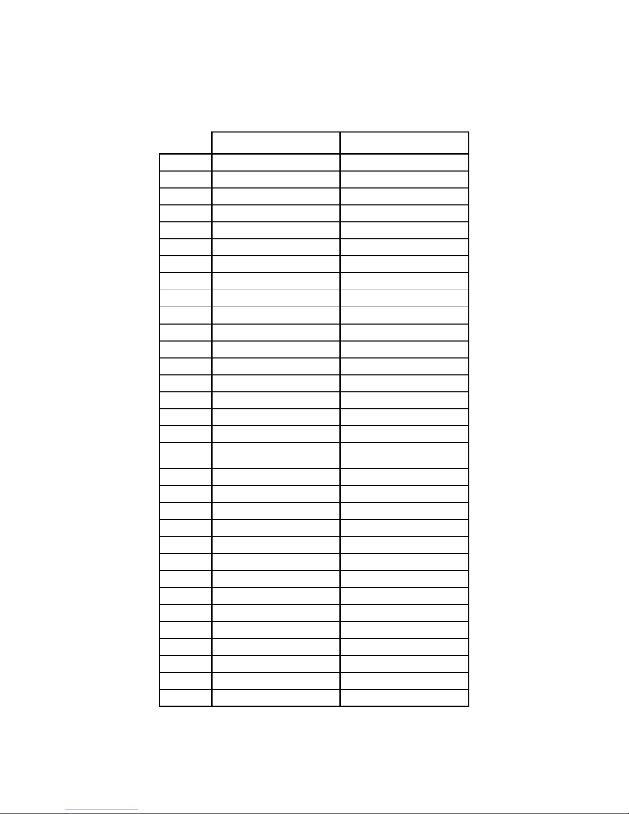
Rear Connector Pin Assignments GPS167 V7.x
ac
1 VCC in (+5V) VCC in (+5V)
2 VCC in (+12V) VCC in (+12V)
3 VDD in (TCXO/OCXO) VDD in (TCXO/OCXO)
4 (reserved, FreqAdjust out)
5
6 P_SEC out
7
8 (reserved, 10 MHz in) P_MIN out
9 /RESET in/out
10 100 kHz out ProgPulse0 out
11 1 MHz out ProgPulse1 out
12 10 MHz out ProgPulse2 out
13 TIME CODE DC out SCL
14 TIME CODE AM out SCL_EN
15 COM2 RxD in SDA
16 COM2 TxD out (reserved, P3.2)
17 COM3 RxD in DCF_MARK out
18 COM3 TxD out (reserved, Vref/TxD2 TTL)
19 GND TIME_SYN out
20 GND (reserved, P2.3)
21 GND F_SYNTH out
22 GND F_SYNTH_OD out
23 GND F_SYNTH_SIN out
24 GND COM1 TxD out
25 GND
26 GND COM0 TxD out
27 GND CAP1 in
28 GND CAP0 in
29 GND COM1 RxD in
30 GND COM0 RxD in
31 GND GND
32 GND GND
male connector according to DIN 41612, type C 64, rows a + c
Page 54

54
Page 55
55
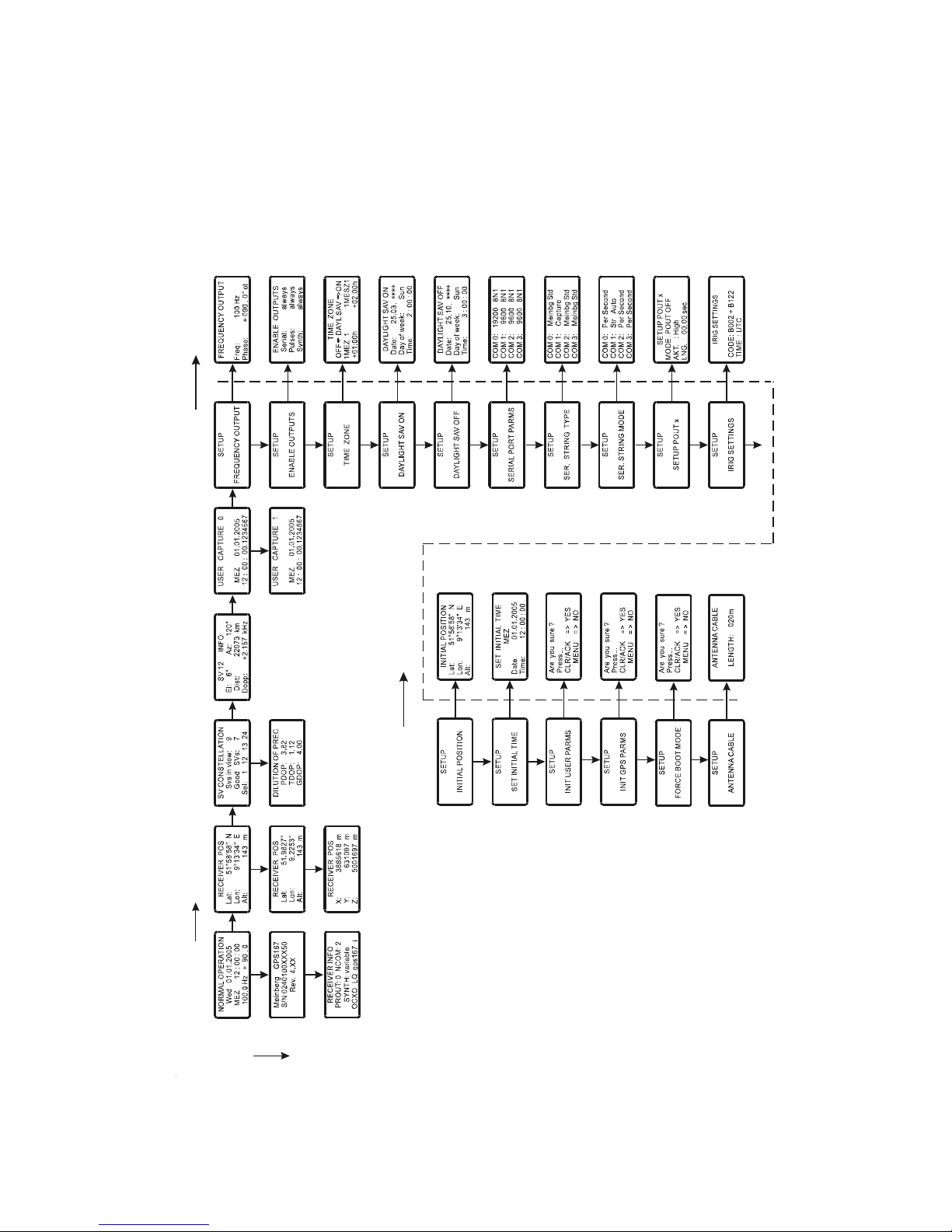
Menu Quick Reference
CLR/ACK
CLR/ACKMENU
NEXT
Page 56

GPS167- E- 250406
 Loading...