

Page 1

FUNKUHREN
GPS161AHS
Technical Information
Operating Instructions
Incl. Windows Software
GPSMON32
Page 2

Impressum
Werner Meinberg
Auf der Landwehr 22
D-31812 Bad Pyrmont
Telefon: ++49 (0) 52 81 / 9309-0
Telefax: ++49 (0) 52 81 / 9309-30
May 27, 2005
Page 3

Table of contents
Impressum............................................................................................ 2
General information............................................................................. 5
Block diagram GPS161AHS................................................................ 6
GPS161AHS features........................................................................... 7
Time zone and daylight saving .................................................. 7
Asynchronous serial port ........................................................... 7
Installation ........................................................................................... 8
Power supply .............................................................................. 8
Mounting the antenna................................................................. 8
Powering up the system ............................................................. 9
The front panel layout .......................................................................... 9
FAIL LED................................................................................... 9
LOCK LED ................................................................................. 9
BSL Key ................................................................................... 10
BNC connector GPS Ant .......................................................... 10
Assignment of the DSUB connector ........................................ 10
Replacing the lithium battery ............................................................ 11
CE label.............................................................................................. 11
Technical specifications GPS161AHS .............................................. 12
Technical specifications of antenna ......................................... 14
Assembly with CN-UB/E (CN-UB-280DC) ............................ 15
Format of the Meinberg standard time string.......................... 16
Format of the Meinberg GPS Time String .............................. 17
Format of the SAT time string................................................. 18
Format of the NMEA (RMC) string ........................................ 19
Format of the ABB-SPA timestring......................................... 20
Format of the Computime Time String ................................... 21
Format of the time string Uni Erlangen (NTP) ....................... 22
Page 4

4
Diskette with Windows Software GPSMON32................................. 24
The program GPSMON32 ................................................................. 25
Online Help .............................................................................. 26
Page 5

5
General information
The satellite receiver clock GPS161AHS has been designed to provide an extremly
precise time reference for the generation of serial time telegrams.
The clock was developed for applications where conventional radio controlled
clocks can´t meet the growing requirements in precision. High precision available 24
hours a day around the whole world is the main feature of the system which receives
its information from the satellites of the Global Positioning System.
The Global Positioning System (GPS) is a satellite-based radio-positioning, navigation, and time-transfer system. It was installed by the United States Departement
of Defense and provides two levels of accuracy: The Standard Positioning Service
(SPS) and the Precise Positioning Service (PPS). While PPS is encrypted and only
available for authorized (military) users, SPS has been made available to the general
public.
GPS is based on accurately measuring the propagation time of signals transmitted
from satellites to the user´s receiver. A nominal constellation of 21 satellites together
with 3 active spares in six orbital planes 20000 km over ground provides a minimum
of four satellites to be in view 24 hours a day at every point of the globe. Four
satellites need to be received simultaneously if both receiver position (x, y, z) and
receiver clock offset from GPS system time must be computed. All the satellites are
monitored by control stations which determine the exact orbit parameters as well as
the clock offset of the satellites´ on-board atomic clocks. These parameters are
uploaded to the satellites and become part of a navigation message which is retransmitted by the satellites in order to pass that information to the user´s receiver.
The high precision orbit parameters of a satellite are called ephemeris parameters
whereas a reduced precision subset of the ephemeris parameters is called a satellite´s
almanac. While ephemeris parameters must be evaluated to compute the receiver´s
position and clock offset, almanac parameters are used to check which satellites are
in view from a given receiver position at a given time. Each satellite transmits its
own set of ephemeris parameters and almanac parameters of all existing satellites.
Page 6
66
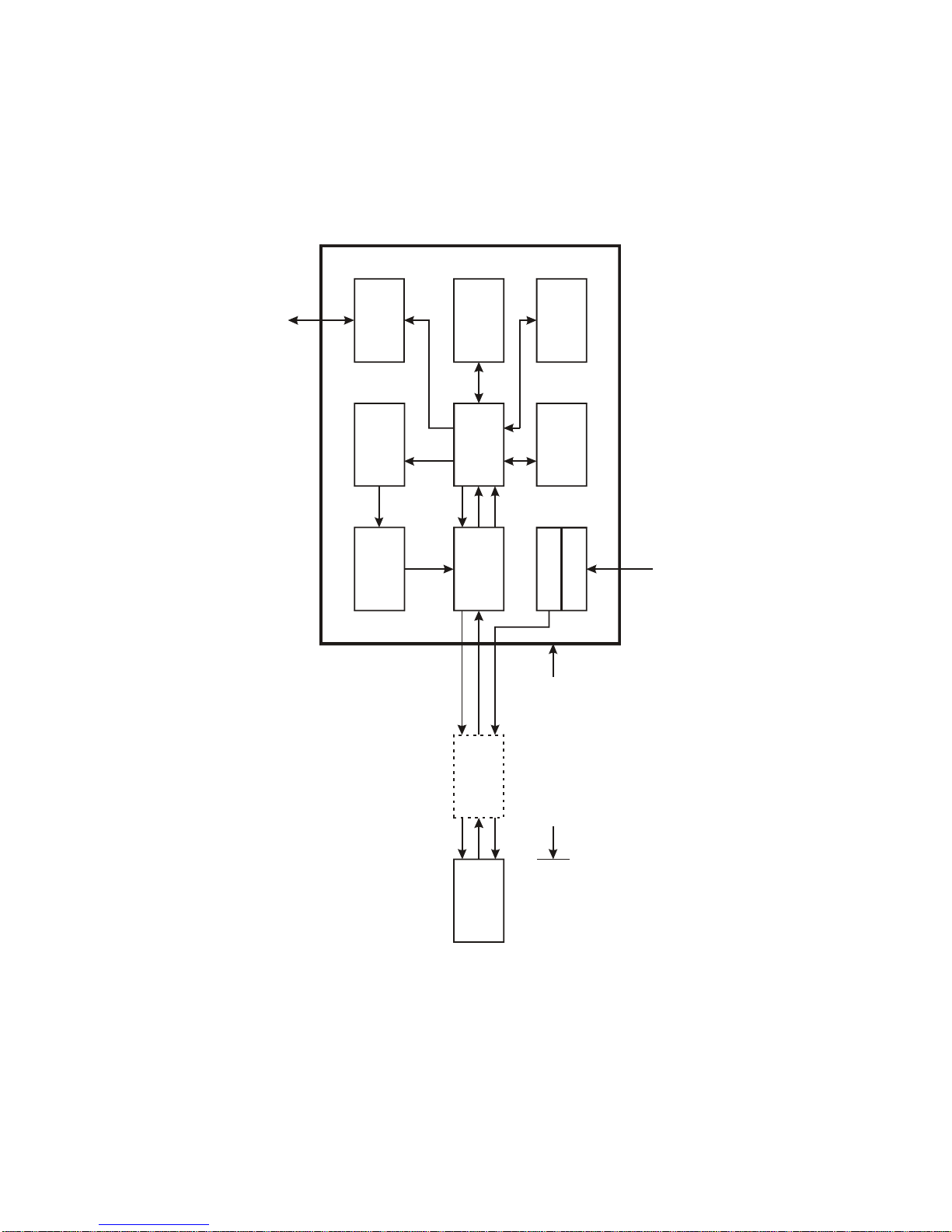
Block diagram GPS161AHS
RS232
driver
RS232 COM00
IF-circuit
correlator
and
microcontroller
master
oscillator
D/A-converter
Flash EPROM
program
memory
GPS161AHS
SRAM
EEPROM
data memories
real time clock
power
100-240VAC
antenna power
internal power
sample
clock
data
addr/data
clock
clock
control
voltage
Tx/Rx
data
addr/data
addr/data
optional
lightning
protector
antenna/
converter
unit
power supply
GPS-signal (IF)
LO-frequency
RG58-cable up to 300 meters
without additional amplifier
Page 7

7
GPS161AHS features
The satellite controlled clock GPS161AHS is designed for mounting on a DIN rail.
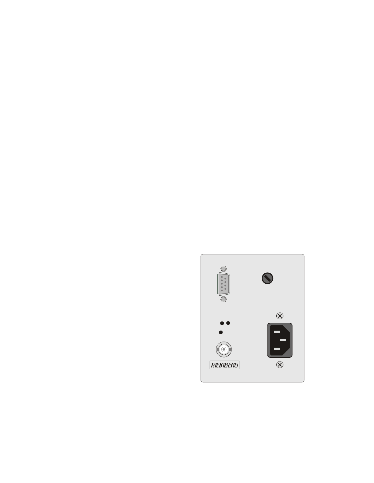
The front panel integrates two LED indicators, a hidden push button, a DSUB- and a
BNC-connector. The receiver is connected to the antenna/converter unit by a 50 Ω-
coaxial cable with length up to 300 m. It is possible to connect up to four receivers to
one antenna by using an optional antenna diplexer.
The navigation message coming from the satellites is decoded by GPS161AHS´s
microprocessor in order to track the GPS system time with an accuracy of better than
±1 µsec. Compensation of the RF signal´s propagation delay is done by automatical
determination of the receiver´s position on the globe. A correction value computed
from the satellites´ navigation messages increases the accuracy of the board´s master
oscillator (TCXO) to ±5.10
-9
and automatically compensates the oscillators aging.
The last recent value is restored from the battery buffered memory at power-up.
Time zone and daylight saving
GPS system time differs from the universal time scale (UTC) by the number of leap
seconds which have been inserted into the UTC time scale after GPS has been
initiated in 1980. The current number of leap seconds is part of the navigation
message supplied by the satellites, so GPS161AHS´s internal real time is based on
UTC.
Conversion to local time including handling of daylight saving year by year can be
done by the receiver´s microprocessor if the corresponding parameters are set up
with the help of the software GPSMON32 (included Windows software).
Asynchronous serial port
An asynchronous serial interface (RS-232) called COM0 is available to the user. In
the default mode of operation, the serial output is disabled until the receiver has
synchronized after power-up. However, the system can be configured to enable this
output immediately after power-up. Transmission speed, framing and the kind of the
time string can be configured. The serial port is sending a time string either once per
second, once per minute or on request with ASCII ´?´ only. The format of the output
strings is ASCII, see the technical specifications for details. The corresponding
parameters can be set up by GPSMON32 (included Windows software) using serial
port COM0.
Page 8

8
Installation
Power supply
The system GPS161AHS is designed for operation with an AC (100V to 240V, 47 Hz
to 63 Hz) power supply. The integrated fuse is available at the front panel.
To avoid potential differences between the signal ground of GPS161AHS and a
post-connected unit installed on different DIN rails, the signal ground of the clock is
insulated from the case.
The case must be grounded by using the rear contact.
Mounting the antenna
The GPS satellites are not stationary but circle round the globe in a period of about 12
hours. They can only be received if no building is in the line-of-sight from the
antenna to the satellite, so the antenna/converter unit must be installed in a location
from which as much of the sky as possible can be seen. The best reception is given
when the antenna has a free view of 8° angular elevation above horizon. If this is not
possible the antenna should be installed with a mostly free view to the equator
because of the satellite courses which are located between latitudes of 55° North and
55° South. If even this is not possible problems occure especially when at least four
sattelites for positioning have to be found.
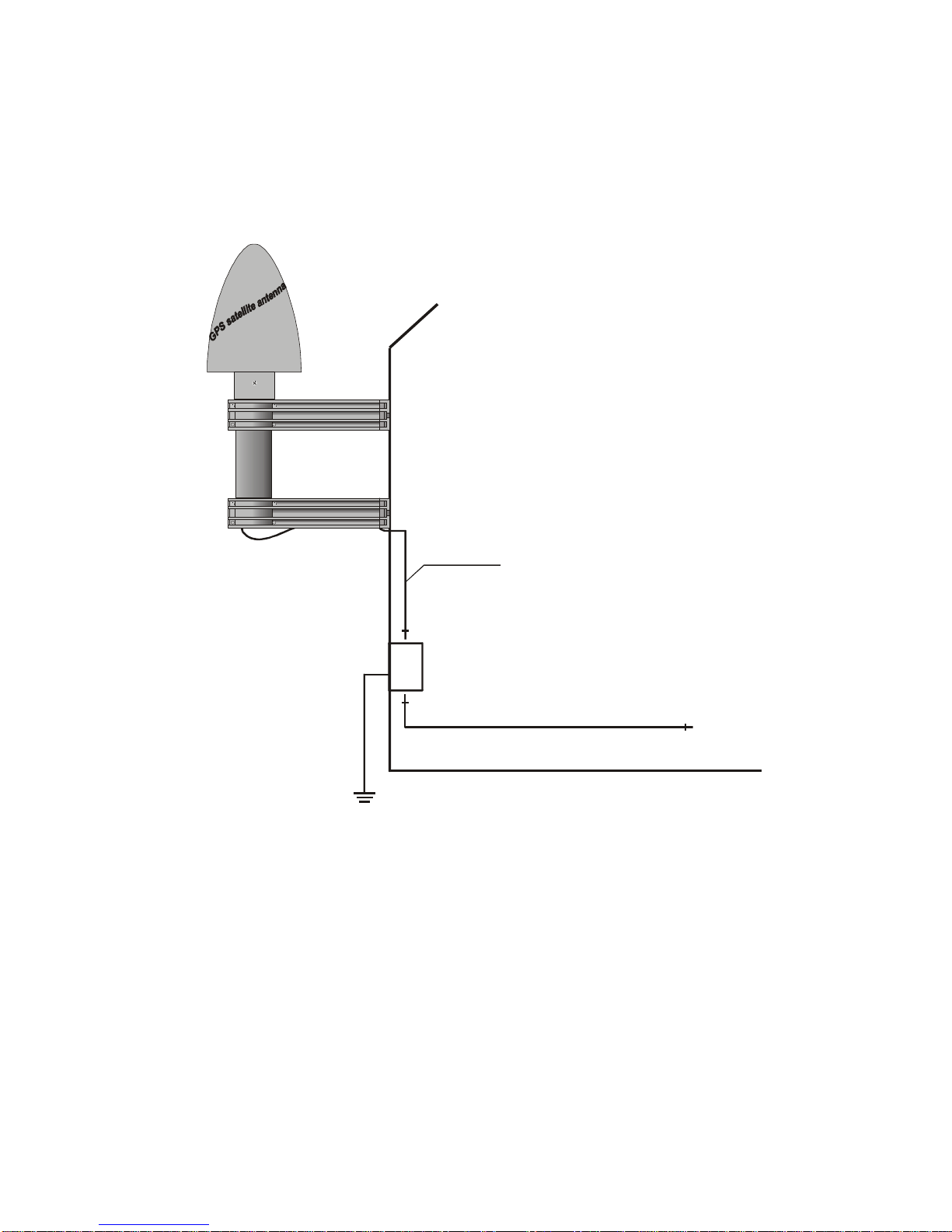
The unit can be mounted using a pole with a diameter up to 60 mm. A standard
coaxial cable with 50 Ω impedance (e.g. RG58C) should be used to connect the
antenna/converter unit to the receiver. Cable thinner than RG58 should be avoided
due to its higher DC resistance and RF attenuation. When using the optional antenna
diplexer the total length of one antenna line between antenna, diplexer and receiver
must not be longer than 300 m. If a cable with less attenuation is used its length may
be increased accordingly (e.g. 600 m with RG213).
If the antenna cable was canned by the user: before powering up
the system, make sure that there is no short-circuit between the
inner and outer conductor of the antenna cable, because this
could cause a fault of GPS161AHS.
Page 9
9
Powering up the system
If both, the antenna and the power supply have been connected, the system is ready to
operate. About 10 seconds after power-up the receiver´s TCXO has warmed up and
operates with the required accuracy. If the receiver finds valid almanac and ephemeris data in its battery buffered memory and the receiver´s position has not changed
significantly since its last operation the receiver can find out which satellites are in
view now. Only a single satellite needs to be received to synchronize and generate
output pulses, so synchronization can be achieved maximally one minute after
power-up.
If the receiver position has changed by some hundred kilometers since last operation, the satellites´ real elevation and doppler might not match those values expected
by the receiver thus forcing the receiver to start scanning for satellites. This mode is
called Warm Boot because the receiver can obtain ID numbers of existing satellites
from the valid almanac. When the receiver has found four satellites in view it can
update its new position and switch to Normal Operation. If the almanac has been
lost because the battery had been disconnected the receiver has to scan for a satellite
and read in the current almanacs. This mode is called Cold Boot. It takes 12 minutes
until the new almanac is complete and the system switches to Warm Boot mode
scanning for other satellites.
The front panel layout
FAIL LED
The FAIL LED is turned on whenever the
receiver is not synchronous to the GPS-system.
LOCK LED
The LOCK LED is turned on if the receiver
has acquired at least four satellites and has
computed its position after power-up. In
normal operation the receiver position is updated continuously as long as at least four
satellites can be received. When the receivers position is known and steady only, a
single satellite needs to be received for synchronization.
GPS161AHS
RS-232
COM 0
GPS
Ant
BSL
500mA SB
100-240VAC
47-63Hz
F
A
I
L
L
O
C
K
Page 10

10
BSL Ke y
Whenever the on-board software must be upgraded or modified, the new firmware
can be downloaded to the internal flash memory using the serial port COM0. There is
no need to open the metal case and insert a new EPROM.
If the BSL key behind the front panel is pressed during operation, a bootstraploader is actived and waits for instructions from the serial port COM0. The new
firmware can be sent to GPS161AHS from any standard PC with serial interface. A
loader program will be shipped together with the file containing the image of the new
firmware.
The contents of the program memory will not be modified until the loader program
has sent the command to erase the flash memory. So, if the BSL key is pressed
unintentionally, the firmware will not be changed accidentially. After the next
power-up, the system will be ready to operate again.
BNC connector GPS Ant
The antenna/converter unit is connected to the receiver circuit of the GPS161AHS
through this connector.
Assignment of the DSUB connector
The serial port COM0 is accessible via a nine-pole female DSUB connector in the
frontpanel. This RS-232 interface can be connected to a computer by using a standard
modem cable. TxD describes the sending, RxD the receiving line of GPS161AHS.
Page 11

11
Replacing the lithium battery
The life time of the lithium battery on the board is at least 10 years. If the need arises
to replace the battery, the following should be noted:
ATTENTION!
Danger of explosion in case of inadequate replacement of
the lithium battery. Only identical batteries or batteries
recommended by the manufacturer m ust be used for re-
placement. The waste battery m ust be disposed as propo-
sed by the manufacturer of the battery.
CE label
This device conforms to the directive 89/336/EWG on the
approximation of the laws of the Member States of the European
Community relating to electromagnetc compatibility .
Page 12

12
Technical specifications GPS161AHS
RECEIVER: 6 channel C/A code receiver with external
antenna/converter unit
ANTENNA: Antenna/converter unit with remote power supply
refer to chapter "Technical specifications of antenna"
ANTENNA
INPUT: Antenna circuit dc-insulated; dielectric strength: 1000V
Length of cable: refer to chapter "Mounting the antenna"
TIME TO SYNCHRONIZATION: One minute with known receiver position and valid almanac
12 minutes if invalid battery buffered memory
BATTERY
BACKUP: Storage of important GPS-system data in the internal RAM
backed-up by lithium battery
lifetime of battery 10 years min.
SERIAL PORT: One asynchronous serial port
COM0 (RS-232)
Baud Rate: 300 up to 19200
Framing: 7N2, 7E1, 7E2, 8N1, 8N2, 8E1
time string selectable:
‘Standard Meinberg’, ‘Meinberg GPS’, ‘SAT'’, ‘ABB-SPA’,
‘Uni Erlangen (NTP)’, ’NMEA (RMC)’, ‘Computime’
default settings: 19200 Bd, 8N1
‘standard Meinberg’
time string per second
mode of operation ‘if sync’
STATUS
INDICATION: Receiver status:
Lock: the reciever was able to compute its position
after power-up
Fail: the receiver is asynchronous to the GPS-system
Page 13

13
POWER
REQUIREMENTS: 100-240 VAC, 47-63 Hz
fuse: 500mA, slow blow
DIMENSION: 105 mm x 85 mm x 104 mm (H x W x D)
CONNECTORS: Coaxial BNC connector for antenna/converter unit
female nine-pole SUB-MIN-D-connector for RS232
power cord receptacle for AC-line
AMBIENT
TEMPERATURE: 0 ... 50°C
HUMIDITY: 85% max.
Page 14
14
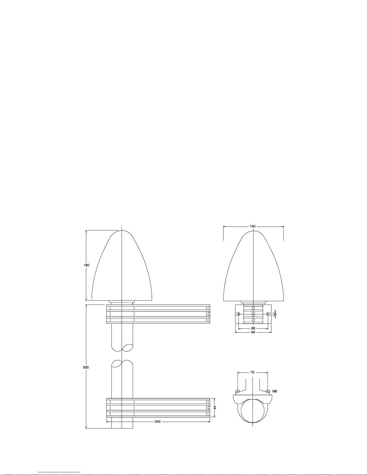
Technical specifications of antenna
ANTENNA: dielectrical patch antenna, 25 x 25mm
receive frequency: 1575.42 MHz
bandwidth: 9 MHz
CONVERTER: local oscillator to converter frequency: 10 MHz
first IF frequency: 35.4 MHz
POWER
REQUIREMENTS: 12V ... 18V, @ 100mA (provided via antenna cable)
CONNECTOR: coax type N, female
AMBIENT
TEMPERATURE: -25 ... +65°C
HOUSING: ABS plastic case for outdoor installation (IP56)
PHYSICAL
DIMENSION:
Page 15
15
Assembly with CN-UB/E (CN-UB-280DC)
Type N / BNC
male
Type N
male
Type N
male
CN-UB/E
1.5m max.
Type N
male
GPS167
Antenna
Meinberg
GPS
As short as possible!
Page 16

16
Format of the Meinberg standard time string
The Meinberg standard time string is a sequence of 32 ASCII characters starting with
the STX (start-of-text) character and ending with the ETX (end-of-text) character.
The format is:
<STX>D:dd.mm.yy;T:w;U:hh.mm.ss;uvxy<ETX>
The letters printed in italics are replaced by ASCII numbers whereas the other
characters are part of the time string. The groups of characters as defined below:
<STX> Start-Of-Text (ASCII code 02h)
dd.mm.yy the current date:
dd day of month (01..31)
mm month (01..12)
yy year of the century (00..99)
w the day of the week (1..7, 1 = Monday)
hh.mm.ss the current time:
hh hours (00..23)
mm minutes (00..59)
ss seconds (00..59, or 60 while leap second)
uv clock status characters:
u: ‘ #’ clock has not synchronized after reset
‘ ‘ (space, 20h) clock has synchronized after reset
v: different for DCF77 or GPS receivers:
‘*’ DCF77 clock currently runs on XTAL
GPS receiver has not checked its position
‘ ‘ (space, 20h) DCF77 clock is sync'd with transmitter
GPS receiver has determined its position
x time zone indicator:
‘U’ UTC Universal Time Coordinated, formerly GMT
‘ ‘ MEZ European Standard Time, daylight saving disabled
‘S’ MESZ European Summertime, daylight saving enabled
y anouncement of discontinuity of time, enabled during last hour
before discontinuity comes in effect:
‘!’ announcement of start or end of daylight saving time
‘A’ announcement of leap second insertion
‘ ‘ (space, 20h) nothing announced
<ETX> End-Of-Text (ASCII code 03h)
Page 17

17
Format of the Meinberg GPS Time String
The Meinberg Standard Time String is a sequence of 36 ASCII characters starting
with the STX (start-of-text) character and ending with the ETX (end-of-text) character. Contrary to the Meinberg Standard Telegram the Meinberg GPS Timestring
carries no local timezone or UTC but the direct GPS time without conversion into
UTC.
The format is:
<STX>D:tt.mm.jj;T:w;U:hh.mm.ss;uvGy;lll<ETX>
The letters printed in italics are replaced by ASCII numbers whereas the other
characters are part of the time string. The groups of characters as defined below:
<STX> Start-Of-Text (ASCII code 02h)
dd.mm.yy the current date:
dd day of month (01..31)
mm month (01..12)
yy year of the century (00..99)
w the day of the week (1..7, 1 = Monday)
hh.mm.ss the current time:
hh hours (00..23)
mm minutes (00..59)
ss seconds (00..59, or 60 while leap second)
uv clock status characters (depending on clock type):
u: ‘ #’ GPS: clock is running free (without exact synchr.)
‘ ‘ (space, 20h)
GPS: clock is synchronous (base accuracy is reached)
v: ‘*’ GPS: receiver has not checked its position
‘ ‘ (space, 20h)
GPS: receiver has determined its position
G time zone indicator 'GPS-Time'
y anouncement of discontinuity of time, enabled during last hour
before discontinuity comes in effect:
‘A’ announcement of leap second insertion
‘ ‘ (space, 20h) nothing announced
lll Number of leap seconds between UTC and GPS-Time
( UTC = GPS-Time + number of leap seconds )
<ETX> End-Of-Text (ASCII code 03h)
Page 18

18
Format of the SAT time string
The SAT time string is a sequence of 29 ASCII characters starting with the STX
(start-of-text) character and ending with the ETX (end-of-text) character. The format
is:
<STX>tt.mm.jj/w/hh.mm.ssMEzzxy<CR><LF><ETX>
The letters printed in italics are replaced by ASCII numbers whereas the other
characters are part of the time string. The groups of characters as defined below:
<STX> Start-Of-Text (ASCII code 02h)
dd.mm.yy the current date:
dd day of month (01..31)
mm month (01..12)
yy year of the century (00..99)
w the day of the week (1..7, 1 = Monday)
hh.mm.ss the current time:
hh hours (00..23)
mm minutes (00..59)
ss seconds (00..59, or 60 while leap second)
zz time zone indicator:
‘Z ‘ MEZ European Standard Time, daylight saving disabled
‘SZ’ MESZ European Summertime, daylight saving enabled
x clock status characters:
‘*’ DCF77 clock currently runs on XTAL
GPS receiver has not checked its position
‘ ‘ (space, 20h) DCF77 clock is sync'd with transmitter
GPS receiver has determined its position
y anouncement of discontinuity of time, enabled during last hour
before discontinuity comes in effect:
‘!’ announcement of start or end of daylight saving time
‘ ‘ (space, 20h) nothing announced
<CR> Carriage return (ASCII code 0Dh)
<LF> Line feed (ASCII code 0Ah)
<ETX> End-Of-Text (ASCII code 03h)
Page 19

19
Format of the NMEA (RMC) string
The NMEA String is a sequence of 65 ASCII characters starting with the ‘$’
character and ending with the characters CR (carriage return) and LF (line-feed). The
format is:
$GPRMC,hhmmss.ss,A,bbbb.bb,n,lllll.ll,e,0.0,0.0,ddmmyy,0.0,a*hh<CR><LF>
The letters printed in italics are replaced by ASCII numbers or letters whereas the
other characters are part of the time string. The groups of characters as defined
below:
$ start character (ASCII-Code 24h)
hhmmss.ss the current time:
hh hours (00..23)
mm minutes (00..59)
ss seconds (00..59, or 60 while leap second)
ss fractions of seconds (1/10 ; 1/100)
A Status (A = time data valid)
(V = time data not valid)
bbbb.bb latitude of receiver position in degrees
leading signs are replaced by a space character (20h)
n latitude, the following characters are possible:
‘N’ north of equator
‘S’ south d. equator
lllll.ll longitude of receiver position in degrees
leading signs are replaced by a space character (20h)
e longitude, the following characters are possible:
‘E’ east of Greenwich
‘W’ west of Greenwich
ddmmyy the current date:
dd day of month (01..31)
mm month (01..12)
yy year of the century (00..99)
a magnetic variation
hh checksum (EXOR over all characters except ‘$’ and ‘*’)
<CR> carriage-return; ASCII-Code 0Dh
<LF> line-feed; ASCII-Code 0Ah
Page 20

20
Format of the ABB-SPA timestring
The ABB SPA timestring is a sequence of 32 ASCII characters starting with the
characters ">900WD" and ending with the <CR> (Carriage Return) character. The
format is:
>900WD:yy-mm-tt_hh.mm;ss.fff:cc<CR>
The letters printed in italics are replaced by ASCII numbers whereas the other
characters are part of the time string. The groups of characters as defined below:
yy-mm-tt the current date:
yy year of the century (00..99)
mm month (01..12)
dd day of month (01..31)
_ Space (ASCII code 20h)
hh.mm;ss.fff the current time:
hh hours (00..23)
mm minutes (00..59)
ss seconds (00..59, or 60 while leap second)
fff milliseconds (000..999)
cc Check sum. EXCLUSIVE-OR result of the previous characters,
displayed as a HEX byte (2 ASCII characters 0..9 or A..F)
<CR> Carriage Return (ASCII code 0Dh)
Page 21

21
Format of the Computime Time String
The Computime time string is a sequence of 24 ASCII characters starting with the T
character and ending with the LF (line feed, ASCII Code 0Ah) character. The format
is:
T:yy:mm:dd:ww:hh:mm:ss<CR><LF>
The letters printed in italics are replaced by ASCII numbers whereas the other
characters are part of the time string. The groups of characters as defined below:
T Start character
yy:mm:dd the current date:
yy year of the century (00..99)
mm month (01..12)
dd day of month (01..31)
ww the day of the week (01..07, 01 = monday)
hh:mm:ss the current time:
hh hours (00..23)
mm minutes (00..59)
ss seconds (00..59, or 60 while leap second)
<CR> Carriage-return (ASCII code 0Dh)
<LF> Line-feed (ASCII code 0Ah)
Page 22

22
Format of the time string Uni Erlangen (NTP)
The time string Uni Erlangen (NTP) of a GPS-clock is a sequence of 66 ASCII
characters starting with the STX (start-of-text) character and ending with the ETX
(end-of-text) character. The format is:
<STX>tt.mm.jj; w; hh:mm:ss; voo:oo; acdfg i;bbb.bbbbn lll.lllle hhhhm<ETX>
The letters printed in italics are replaced by ASCII numbers whereas the other
characters are part of the time string. The groups of characters as defined below:
<STX> Start-Of-Text (ASCII code 02h)
dd.mm.yy the current date:
dd day of month (01..31)
mm month (01..12)
yy year of the century (00..99)
w the day of the week (1..7, 1 = Monday)
hh.mm.ss the current time:
hh hours (00..23)
mm minutes (00..59)
ss seconds (00..59, or 60 while leap second)
v sign of the offset of local timezone related to UTC
oo:oo offset of local timezone related to UTC in hours and minutes
ac clock status characters:
a: ‘ #’ clock has not synchronized after reset
‘ ‘ (space, 20h) clock has synchronized after reset
c: ‘*’ GPS receiver has not checked its position
‘ ‘ (space, 20h) GPS receiver has determined its position
d time zone indicator:
‘S’ MESZ European Summertime, daylight saving enabled
‘ ‘ MEZ European Standard Time, daylight saving disabled
f anouncement of discontinuity of time, enabled during last hour
before discontinuity comes in effect:
‘!’ announcement of start or end of daylight saving time
‘ ‘ (space, 20h) nothing announced
g anouncement of discontinuity of time, enabled during last hour
before discontinuity comes in effect:
‘A’ announcement of leap second insertion
‘ ‘ (space, 20h) nothing announced
Page 23

23
i leap second insertion
‘L’ leap second is actually inserted
(active only in 60th sec.)
‘ ‘ (space, 20h) no leap second is inserted
bbb.bbbb latitude of receiver position in degrees
leading signs are replaced by a space character (20h)
n latitude, the following characters are possible:
‘N’ north of equator
‘S’ south of equator
lll.llll longitude of receiver position in degrees
leading signs are replaced by a space character (20h)
e longitude, the following characters are possible:
‘E’ east of Greenwich
‘W’ west of Greenwich
hhhh altitude above sea level in meters
leading signs are replaced by a space character (20h)
<ETX> End-Of-Text (ASCII-code 03h)
Page 24

24
Diskette with Windows Software GPSMON32
Page 25
25
The program GPSMON32
The program GPSMON32 can be used to monitor and program all essential
functions of Meinberg GPS-Receivers. The Software is executable under Win9x/2k/
NT. To install GPSMON32 just run Setup.exe from the included diskette and follow
the instructions of the setup program.
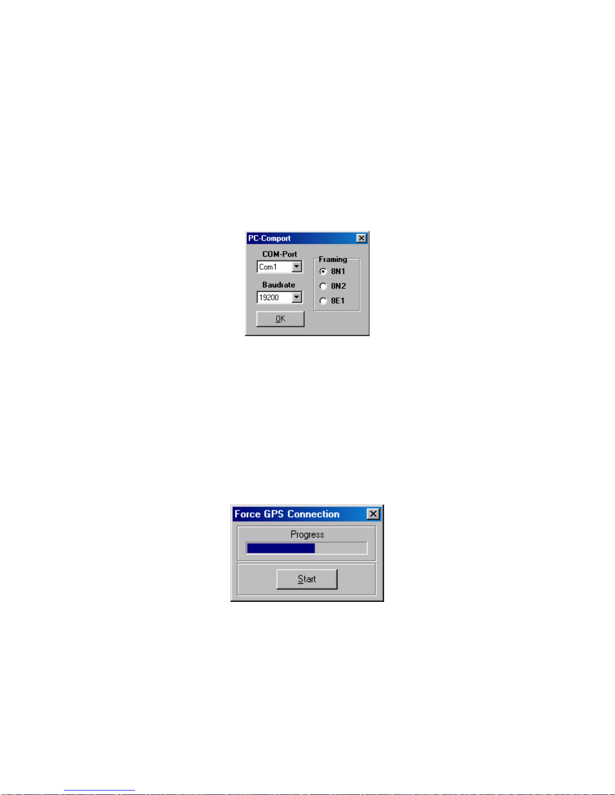
To obtain a connection between your PC and the GPS-receiver, connect the receivers
COM0 port to a free serial port of your PC. The PCs comport used by the program
GPSMON32 can be selected in submenu 'PC-Comport' in menu 'Connection'.
Also transfer rate and framing used by the program are selected in this menu.
Communication between the clock and the PC comes about, only if the GPS serial
port is configured in the same way as the PCs comport. You can enforce an access, if
the GPS serial port is not configured with appropriate parameters for communication. Select the menu item 'Enforce Connection' in menu 'Connection' and click
'Start' in the appearing window. Some firmware versions of GPS167 do not support
this way of setting up a connection. If 'Enforce Connection' doesn't succeed
apparently, please change the serial port parameter of GPS COM0 manually to the
PCs parameters.
Page 26
26
Online Help
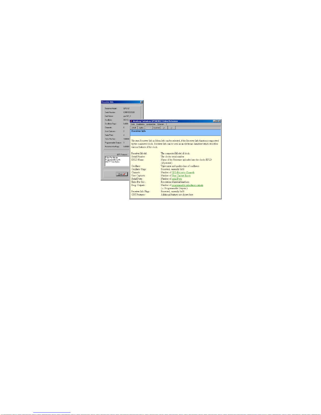
The online help can be started by clicking the menu item 'Help' in menu Help. In
every program window a direct access to a related help topic can be obtained by
pressing F1. The help language can be selected by clicking the menu items Deutsch/
Englisch in the Help Menu.
Page 27

27
Page 28

 Loading...