

Page 1

FUNKUHREN
Technical Information
Operating Instructions
DU35S
Page 2

Impressum
Werner Meinberg
Auf der Landwehr 22
D-31812 Bad Pyrmont
Phone: ++49 52 81 - 9309-0
Fax: ++49 52 81 - 9309-30
Internet: http://www.meinberg.de
Email: info@meinberg.de
March 15, 2005
Page 3

Table of Contents
Impressum ............................................................................................ 2
Features of the DU35S.........................................................................5
Installation............................................................................................ 5
Power Supply.............................................................................. 5
DU35S as Stand Alone Clock .............................................................. 6
DU35S as Slave Clock ......................................................................... 6
Usage of the Buttons MENU and SET ................................................ 6
The Menus in Detail ................................................................... 7
Time .................................................................................. 7
Date ................................................................................... 7
Language ........................................................................... 7
Mode..................................................................................7
Brightness.......................................................................... 7
Serial ................................................................................. 7
Time Zone ......................................................................... 8
Daylight Saving................................................................. 8
Exit .................................................................................... 9
Rear View DU35S ............................................................................. 10
Rear Panel Connectors.............................................................. 11
CE Label ............................................................................................ 11
Connection Exaples............................................................................ 12
Pin Assignments of SUB-D Connector IN ............................... 14
Pin Assignments of SUB-D Connector OUT ........................... 14
Technical Specifications: ................................................................... 15
Format of the Meinberg Standard Time String ........................ 16
Jumper Arrangement.......................................................................... 17
Page 4

Page 5
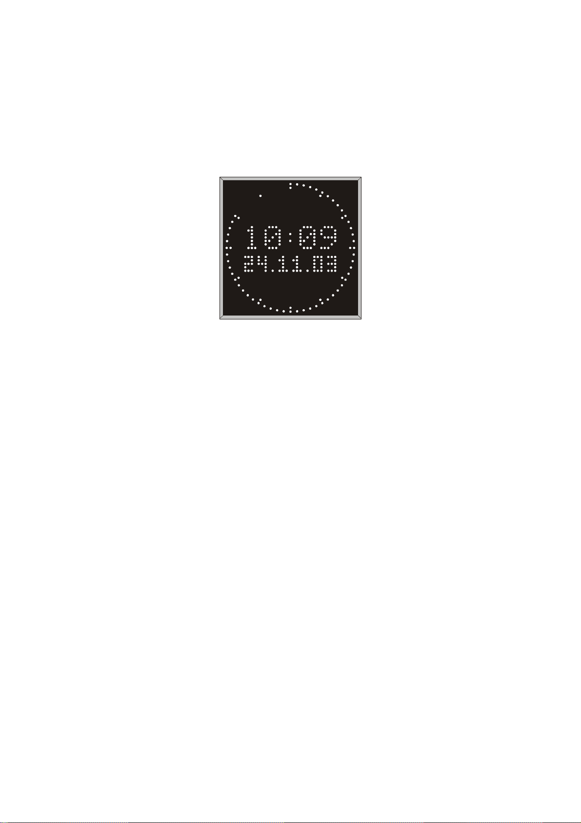
Features of the DU35S
The large display DU35S is a 300mm x 300mm LED matrix display that shows the
time and date. It can be run either as a free running stand alone clock or as a serial
driven slave clock.
Fig.1:
Front View
In case of supply voltage failure the on board RTC keeps the time based on XTAL
for at least 10 years. The language displayed can be choosen. The wall mounted
housing of the DU35S is made of plastic coated steel sheet.
The power connector, the (optional) antenna input and the RS232/20mA interfaces
provided by DU35S are accessible via connectors in the rear panel of the case.
Installation
P ower Supply
The requested supply voltage is applied via the power cord receptacle in the rear
panel. After connecting the power cord the system is ready to operate and the time/
date is displayed immediately.
5
Page 6

DU35S as Stand Alone Clock
After connecting the mains power the shown time can be set by the two buttons in the
rear panel of the case. The accuracy of the time depends on the precision of the
internal quartz base.
An automatic changeover of daylight saving can be programmed as described in
section "Daylight Saving".
DU35S as Slave Clock
The DU35S can be synchronized by a preconnected radio clock that sends time strings
periodically. When the radio clock stops sending time strings the DU35S continues by
running on XTAL.
The data transmission occurs either:
- via RS232 or
- via 20mA current loop.
It is possible to connect several DU35S' or other similar displays via series
connection to one radio clock.
Usage of the Buttons MENU and SET
The time and date, the language, the brightness, the serial parameters and the automatic changeover of daylight saving can be edited by using the buttons MENU and SET.
The button MENU is used to change over from the normal operation mode into the
'set parameters' mode and to select the different menus. The button SET is used to
modify the selected parameter. When leaving the menu by pushing MENU the
modification is acknowledged. When no button is pushed for more than 30 seconds
the DU35S goes back into normal operation mode with loosing the last modification
that was not acknowledged. The menus in detail are described below.
6
Page 7

The Menus in Detail
Time
When pressing SET in this menu the actual valid time of the DU35S appears in the
display with a blinking digit of the hours. Pressing and keeping pushed the SET button
for at leasr half a second before releasing lets the blinking digit increment by one. This
can be repeated until the value has reached the target. One more brief pressure of SET
lets the next digit begin to blink that can be incremented in the same way. Pressing
MENU acknowledges the modification and changes over to the next menu.
Date
The date can be modified in the same manner that is described above.
Language
When pressing SET in this menu the actual valid language of the DU35S' menu texts
appears in the display. Renewed pressing SET causes another language appearing.
When the wanted (and available) language is displayed, the menu is to leave by
pressing MENU.
Mode
DU35S is able to show the time and/or date in different formats. One of these different
display modes can be selected in this menu by pressing SET. Press the MENU button
to acknowledge and to leave this menu.
Brightness
The brightness of the display can be set in three steps. Press SET in this menu to
increment an integer between 1 and 3 where 1 means the most dimmed step and 3
means the fully brightness. Press MENU to acknowledge and to leave this menu.
Serial
Baudrate and framing of the serial interface can be set using this menu. Available
baudrates are: 2400, 4800, 9600 and 19200. The framing can be choosen between 7E2
and 8N1. Setting this parameters occurs similar to the procedures described before. A
short brief push to the SET button changes to the next parameter to be set, a longer
push of SET lets the blinking value increment by one. Press MENU to acknowledge
and to leave this menu.
7
Page 8

Time Zone
This menu lets the user enter a value for the time offset to UTC each for winter time
(daylight saving off) and for summer time (daylight saving on). This setting as well as
the following described Daylight Saving settings come into affect only when the clock
is used as a free running clock. Otherwise the changeover in daylight saving occurs
according to the reference source (e.g. DCF77). Pressing MENU acknowledges the
changings and switches to the next menu.
Daylight Saving
W/S D:
In this menu the automatic changeover from daylight saving off to daylight saving
on can be edited. Pressing SET lets the user edit the date of the changeover as described before but there is one peculiarity:
Beginning of daylight saving may either be defined by exact dates for a single year or
using an algorithm which allows the DU35S to recompute the effective dates year by
year.
The example beside shows how to enter the first case:
The day-of-week does not need to be specified and
therefore is displayed as wildcard (*). The date of next
years changeover has to be entered as well (year by year).
In the second case the day-of-week must be specified. Then, starting from the configured date, daylight saving starts the first day whitch matches the configured day-ofweek.
The example shows what has to be entered when daylight
saving has to start the last sunday in march every year:
The year (**) does not need to be specified because the
changeover algorithm is valid for all further years, too.
W/S T:
In this menu the time of the changeover from daylight saving off to daylight saving
on can be edited. Pressing SET lets the user edit the time of the changeover as described before. Press MENU to acknowledge and to leave this menu.
30 / 03
03 *
25 / 03
** 7
8
Page 9

S/W D:
This menu lets the user enter the date of the automatic changeover from daylight
saving on to daylight saving off in the same manner described in the prvious section:
Ending of daylight saving may either be defined by exact dates for a single year or
using an algorithm which allows the DU35S to recompute the effective dates year by
year.
The example beside shows how to enter a fixed
time/date for a singe years daylight saving end:
The time/date of next years changeover has to
be entered as well (year by year).
When daylight saving has to end the last sunday in
october every year the following has to be entered:
(day-of-week: 1 = monday, 7 = sunday).
S/W T:
In this menu the time of the changeover from daylight saving on to daylight saving
off can be edited. Pressing SET lets the user edit the time of the changeover as
already described. Press MENU to acknowledge and to leave this menu.
26 / 10
03 *
25 / 10
** 7
Exit
Pressing SET in this menu lets the DU35S switch over from the 'set parameters' mode
into the normal operation mode. All changes of the settings are valid now.
9
Page 10

Rear Vie w DU35S
Fig.2:
Rear Panel View
MENU SET
IN
OUT
ANT
T250mA L/250V
230V
IN serial input for preconnected master clock (time strings)
OUT serial output (time strings) for further DU35S' or
other equivalent Displays.
ANT not connected
Power Power supply cord (85-264VAC / 120-375VDC)
FUSE Fuse (250mA SB)
MENU/SET Buttons to configure the DU35S
Because it is possible to preconnect clocks in different ways it is necessary to set the
jumpers on the main board correctly (see examples Fig.3-6). The factory default
setting of the jumpers is: syncronisation by RS232 time strings.
10
Page 11

Rear Panel Connectors
Name Type Signal Cable
IN 25 pin SUB-D RS232 shielded data line
OUT 9 pin SUB-D RS232 shielded data line
Power power cord receptacle 85-264VAC / power supply cord
120-375VDC
CE Label
This device conforms to the directi ve 89/336/EWG on the
approximation of the laws of the Member States of the European
Community relating to electromagnetc compatibility .
11
Page 12

Connection Exaples
Hauptuhr (DCF / GPS)
oder
DU35K* (D Sub 9 OUT)
1PMJ1PMJ
1PMJ1PMJ2PMJ2PMJ
1PMJ
2PMJ2PMJ5PMJ5PMJ
2PMJ
2*
7*
5PMJ5PMJ6PMJ6PMJ
5PMJ
DU35K
D Sub25 IN
2
7
6PMJ6PMJ7PMJ7PMJ
6PMJ
XXXX 232SR
Fig.3:
Jumper settings for operating mode: 'Synchronisation by RS232'
7PMJ7PMJ
7PMJ
Hauptuhr (DCF / GPS)
oder
DU35K* (D Sub 9 OUT)
1PMJ1PMJ
1PMJ1PMJ2PMJ2PMJ
1PMJ
4 *
1 *
2PMJ2PMJ5PMJ5PMJ
2PMJ
5PMJ5PMJ6PMJ6PMJ
5PMJ
25
23
DU35K
D Sub25 IN
+V
6PMJ6PMJ7PMJ7PMJ
6PMJ
evissapevissapevitcaevitcaAm02
Fig.4:
Jumper settings for operating mode: 'Synchronisation by 20mA Current Loop'
with passive output onto active input
7PMJ7PMJ
7PMJ
12
Page 13

Hauptuhr (DCF / GPS)
oder
DU35K* (D Sub 9 OUT)
DU35 K
D Sub25 IN
+V -V
1PMJ1PMJ
1PMJ1PMJ2PMJ2PMJ
1PMJ
2PMJ2PMJ5PMJ5PMJ
2PMJ
4 *
1 *
5PMJ5PMJ6PMJ6PMJ
5PMJ
25
23
6PMJ6PMJ7PMJ7PMJ
6PMJ
evitcaevitcaevissapevissapAm02
Fig.5:
Jumper settings for operating mode: 'Synchronisation by 20mA Current Loop'
with active output onto passive input
7PMJ7PMJ
7PMJ
13
Page 14

Pin Assignments of SUB-D Connector IN
A
2 Input Time Strings - RS232
3 Output RX_INF - RS232
7 Ground
17 Output RX_INF - 20mA 23 Input Time Strings - 20mA +
24 Output RX_ INF - 20mA +
25 Input Time Strings - 20mA -
Pin Assignments of SUB-D Connector OUT
1 Output Time Strings - 20mA 2 Output Time Strings - RS232
3 Input RX_INF - RS232
4 Output Time Strings - 20mA +
5 Ground
6 Input RX_INF - 20mA +
7 Input RX_INF - 20mA -
Eingang_TLX/RS23
usgang_RX_INF/RS232
Masse
1
2
3
4
5
6
7
8
9
10
11
12
13
D Sub 25 IN
Fig.7:
14
IMP_Eingang
15
16
IMP_Eingang
17
Ausgang_RX _INF/20 m A -
18
19
20
21
22
23
Eingang_TLX/20 m A +
24
Ausgang_RX _INF/20 m A +
25
Eingang_TLX/20 m A -
Ausgang_TLX/20 m A -
Ausgang_TLX/RS232
Eingang_RX_INF/RS232
Ausgang_TLX/20 m A +
Masse
1
2
3
4
5
6
7
8
9
D Sub 9 OUT
Pin Assignments of SUB-D Connectors IN and OUT
Eingang_RX_ INF/20mA +
Eingang_RX_INF/20 m A IMP_Ausgang
IMP_Ausgang
(DCF77 variant: The DSub connector (IN) at the rear panel has no effect!)
14
Page 15

Technical Specifications:
OPERATION
MODE: - as free running quartz clock with internal RTC
- as slave clock synchronized by radio clock or master clock
with serial time strings
DISPLAY: LED dot matrix display 5x7 dots, 2 lines (50mm character
height), LED circle for indication of seconds
INPUTS: serial interface, RS232 or 20mA current loop (passive/active)
DSUB25 connector
OUTPUTS: serial interface, RS232 or 20mA current loop (passive/active)
DSUB9 connector
BAUDRATE: 2400, 4800, 9600 or 19200 baud
FRAMING: 7E2 or 8N1
TIME STRING: see "Format of the Meinberg Standard Time String"
BUFFERING: In case of supply voltage failure the on-board RTC keeps the
time based on XTAL for more than 10 years.
POWER
REQUIREMENTS: 85-264VAC, 50/60Hz / 120-375VDC, approx. 22VA
FUSE: 250mA T (slow blowing)
PHYSICAL
DIMENSION: 323mm x 323mm x 57mm
WEIGHT: 4,7kg
15
Page 16

Format of the Meinberg Standard Time String
The Meinberg Standard Time String is a sequence of 32 ASCII characters starting
with the STX (start-of-text) character and ending with the ETX (end-of-text) character. The format is:
<STX>D:dd.mm.yy;T:w;U:hh.mm.ss;uvxy<ETX>
The letters printed in italics are replaced by ASCII numbers whereas the other
characters are part of the time string. The groups of characters as defined below:
<STX> Start-Of-Text (ASCII code 02h)
dd.mm.yy the current date:
dd day of month (01..31)
mm month (01..12)
yy year of the century (00..99)
w the day of the week (1..7, 1 = Monday)
hh.mm.ss the current time:
hh hours (00..23)
mm minutes (00..59)
ss seconds (00..59, or 60 while leap second)
uv clock status characters:
u: ‘#’ clock has not synchronized after reset
‘ ‘ (space, 20h) clock has synchronized after reset
v: ‘*’ DCF77 clock currently runs on XTAL
‘ ‘ (space, 20h) DCF77 clock is sync'd with transmitter
x time zone indicator:
‘U’ UTC Universal Time Coordinated, formerly GMT
‘ ‘ MEZ European Standard Time, daylight saving disabled
‘S’ MESZ European Summertime, daylight saving enabled
y anouncement of discontinuity of time, enabled during last hour
before discontinuity comes in effect:
‘!’ announcement of start or end of daylight saving time
‘A’ announcement of leap second insertion
‘ ‘ (space, 20h) nothing announced
<ETX> End-Of-Text (ASCII code 03h)
16
Page 17

Jumper Arrangement
JMP11
EXT INT
repmuJrepmuJ
repmuJrepmuJ : :tluafeD:tluafeD
repmuJ
,1PMJ;pooltnerrucAm02gnirtsemittuptuOevissap
2PMJevissap/evitca
,3PMJ;pooltnerrucAm02OFNI_XRtuptuOevissap
4PMJevissap/evitca
,5PMJ;pooltnerrucAm02gnirtsemittupnIevitca
6PMJevissap/evitca
7PMJAm02/232SR:gnirtsemittcelestupnI232SR
,8PMJ;pooltnerrucAm02OFNI_XRtupnIevitca
9PMJ
01PMJAm02/232SR:OFNI_XRtcelestupnI232SR
11PMJ!egnahctonoD-TNIsyawlaTNI
20 mA
20 mA
JMP7
JMP10
RS232
RS232
AKT
AKT
AKT
AKT
AKT
AKT
AKT
AKT
JMP1
JMP2
JMP3
JMP4
JMP5
JMP6
JMP8
JMP9
PAS
PAS
PAS
PAS
PAS
PAS
PAS
PAS
:tluafeD:tluafeD
:tluafeD
17
Page 18

 Loading...