

Page 1

FUNKUHREN
Technical Information
Operating Instructions
DU35K
Page 2

Impressum
Werner Meinberg
Auf der Landwehr 22
D-31812 Bad Pyrmont
Phone: ++49 52 81 - 9309-0
Fax: ++49 52 81 - 9309-30
Internet: http://www.meinberg.de
Email: info@meinberg.de
September 3, 2004
Page 3

Inhaltsübersicht
General Information about DCF77 ...................................................... 5
Features of the DU35K ........................................................................ 6
Installation............................................................................................6
Power Supply.............................................................................. 6
DU35K as Stand Alone Clock ............................................................. 7
DU35K as Slave Clock ........................................................................ 7
Synchronisation by serial Time Strings:..................................... 7
Synchronisation by Pulses per Minute: ...................................... 7
DU35K as Radio Clock........................................................................ 8
Mounting the Antenna ................................................................ 9
Usage of the Buttons MENU and SET .............................................. 10
The Menus in Detail ................................................................. 10
Time & Date.................................................................... 10
Language ......................................................................... 10
Brightness........................................................................ 10
Daylight Saving............................................................... 10
Winter/Summer Changeover........................................... 11
Summer/Winter Changeover........................................... 11
Exit .................................................................................. 11
Rear View DU35K............................................................................. 12
Rear Panel Connectors.............................................................. 13
CE Label ............................................................................................ 13
Connection Exaples............................................................................ 14
Pin Assignments of SUB-D Connector IN ............................... 16
Pin Assignments of SUB-D Connector OUT ........................... 16
Technical Specifications: ................................................................... 17
Format of the Meinberg Standard Time String ........................ 18
Jumper Arrangement.......................................................................... 19
Page 4

Page 5

General Information about DCF77
The radio remote clocks made by Meinberg receive the signal from the long wave
transmitter DCF77. This long wave transmitter installed in Mainflingen near Frankfurt/Germany transmits the reference time of the Federal Republic of Germany. This
time reference is either the Central European Time (Mitteleuropäische Zeit, MEZ) or
the Central European Summer Time (Mitteleuropäische Sommerzeit, MESZ). The
transmitter is controlled by the atomic clock plant at the Federal Physical Technical
Institute (PTB) in Braunschweig/Germany and transmits the current time of day, date
of month and day of week in coded second pulses. Once every minute the complete
time information is available.
At the beginning of every second the amplitude of the high precision 77.5 kHz
carrier frequency is lowered by 75% for a period of 0.1 or 0.2 sec. The length of these
time marks represent a binary coding scheme using the short time mark for logical
zeroes and the long time mark for logical ones. The information on the current date
and time as well as some parity and status bits can be decoded from the time marks of
the 15th up to the 58th second every minute. The absence of any time mark at the 59th
second of a minute signals that a new minute will begin with the next time mark.
Our radio remote clocks decode the highly accurate information on date and time
within a wide range around Germany. So some of our clocks are installed in Bilbao/
Spain as well as in the city of Umeå in northern Sweden - fully satisfying the
requirements of the users. The radio remote clocks automatically switch to summertime and back. The reception of the time information is free of charge and does not need
to be registered.
Generally it is important to position the antenna in an optimal way. It should be
mounted at least 30 centimeters away from the clock unit and from solid steel. The
antenna should be aligned at a right angle to the direction of the transmitter (Frankfurt).
Figure: Decoding Scheme
P
8
3
M
4
Year of the Century
Month of Year
Day of Week
Day of Month
0
0
2
0
1
0
8
4
2
1
1
0
50
8
4
2
1
4
2
1
40
0
2
0
1
8
4
2
1
0
30
2
0
P
2
0
1
Hour
P
8
1
1
4
2
(reserved)
10
R
A
1
Z
1
Z
2
20
A
2
S
1
2
4
8
1
0
2
4
0
Minute
0
M Start of Minute (0.1 s)
R RF T ransmission via secon dary antenna
A1 Announcement of a ch ange in dayligh t saving
Z1, Z2 Time zone identification
Z1, Z2 = 0, 1: Daylight saving disabled
Z1, Z2 = 1, 0: Daylight saving enabled
A2 Announcement of a lea p second
S Start of time code information
P1, P2, P3 Even parity bits
5
Page 6
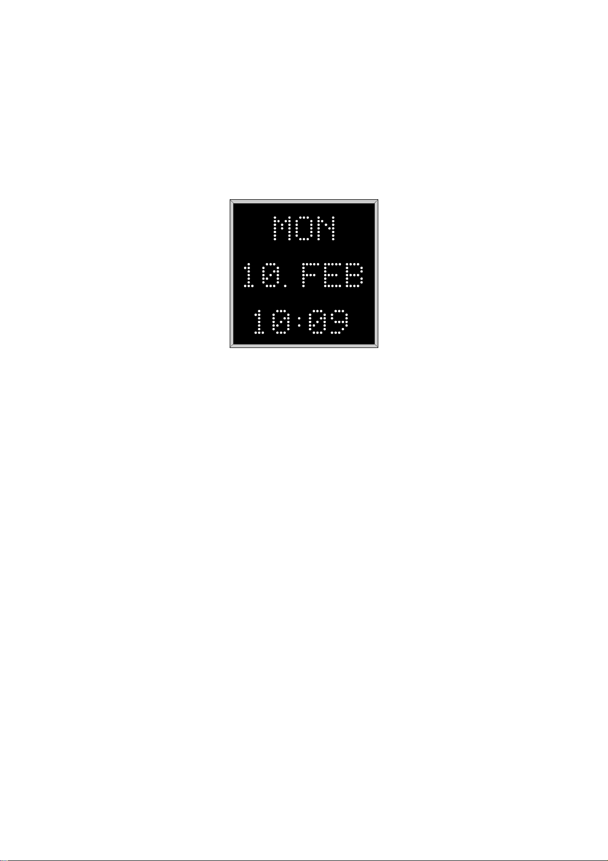
Features of the DU35K
The large display DU35K is a 50mm hight LED matrix display that shows time and
date in three lines with eight characters each as follows: day of week, day of month,
month, hours, minutes and seconds. It is available as a free running stand alone clock,
as a slave clock or as a radio clock with integrated DCF77 receiver.
Fig.1:
Front View
The DCF variant provides automatic changeover of daylight saving. In case of
supply voltage failure the on board RTC keeps the time based on XTAL for at least 10
years. The language displayed can be choosen. The wall mounted housing of the
DU35K is made of plastic coated steel sheet.
The power connector, the antenna input and the RS232/20mA interfaces provided
by DU35K are accessible via connectors in the rear panel of the case.
Installation
P ow er Suppl y
The requested supply voltage of 230V/50Hz is applied via the power cord receptacle
in the rear panel. After connecting the power cord and the antenna (only DCF variant)
the system is ready to operate. Time and date become visible on the display.
6
Page 7

DU35K as Stand Alone Clock
After connecting the power supply to the 230V/50Hz net the appearing time/date can
be set by the two buttons in the rear panel of the case. The accuracy of the time
depends on the precision of the internal quartz base.
An automatic changeover of daylight saving can be programmed as described in
section "Daylight Saving".
DU35K as Slave Clock
There are two possibilities of synchronisation. The DU35K can be synchronized either
by serial time strings or by pulses per minute. The selection can be set by jumper JP19
on the board (see section "Jumper Arrangement").
Synchronisation by serial Time Strings:
A preconnected radio clock sends the time strings to the DU35K. When the radio
clock stops sending time strings the DU35K continues by running on XTAL.
The data transmission occurs either:
- via RS232 or
- via 20mA current loop.
It is possible to connect several DU35Ks or other Displays via serial interface to
one radio clock.
Synchronisation by Pulses per Minute:
The DU35K can also operate as a normal slave clock. A preconnected master clock
generates the minute slave line with pulse levels up to 48V. Installing the system it is
necessary that the DU35Ks time match about ±15 sec. with the master clocks time.
Synchronisation with the master clock is indicated by a dot between date and time on
the display: When the dot is visible the DU35K runs free, when the dot dissappears the
clock is syncronized. Synchronisation is possible only two times per hour. An automatic changeover of daylight saving can be programmed as described in section "Automatic Changeover of Daylight Saving".
7
Page 8

DU35K as Radio Clock
It is not possible to run this variant of the DU35K as a slave clock. The DSUB
connector (IN) at the rear panel has no effect. The DSUB connector (OUT) can be
connected to further DU35Ks or similar systems to run them as slave clocks.
An external ferrit antenna is used to receive the signal from DCF77 and supplies it
to the on-board LF receiver where it is demodulated by a synchronous detector with
automatic gain control. The demodulated time marks are fed to the clock´s microprocessor.
The time marks from the receiver circuit are filtered and decoded by the microprocessor system. Parity and consistency checks over a period of two minutes take care
for detecting errors in the received time string. The checked and decoded time is
written to the on-board real time clock and spread by the interfaces. A software
watchdog lets the microprocessor recover from malfunction. A power-fail comparator
resets the microprocessor if the supply voltage drops below a specified threshold.
In case of supply voltage failure the on-board real time clock keeps the time
powered by a lithium battery which has a live time of at least 10 years guaranteed.
After powering up the system the time keeped in the real time clock is displayed
immediately. A dot below the colons between hours and minutes on the display
indicates the DCF77 signal. This "Modulation Dot" appears until the first synchronisation of the clock. If the antenna is installed properly and the signal from DCF77 can be
received without strong distortions, the "Modulation Dot" starts blinking exactly once
per second, corresponding to the time marks from DCF77. Because of a better control
an acoustic signal is added to the "Modulation Dot" for 2.5 minutes. After loss of
reception for more than 6 hours the colons between hours and minutes begins to blink.
8
Page 9

Mounting the Antenna
Generally it is important to position the antenna in an optimal way. The antenna
should be aligned at a right angle to the direction of the transmitter (Frankfurt). It
should be mounted at least 30 centimeters away from the clock unit and from solid
steel. A distance of several meters is recommended to all TVs or computer monitors.
In order to get the maximum signal, the antenna should be aligned carefully. If the
antenna is installed properly and the signal from DCF77 can be received without
strong distortions, the "Modulation Dot" starts blinking exactly once per second,
corresponding to the time marks from DCF77. If this dot flashes intermediately, there
is some electrical noise around which prevents the microprocessor from decoding the
time message. So a better location for the antenna must be found. In case of correct
reception it takes up to three minutes after power-up until the clock is synchronized
and the "Free Running Dot" is turned off.
The scope of supply (only DCF77 variant) includes an active ferrite antenna for
indoor mounting (AI01) and 5m of RG175 coaxial cable. When mounting the antenna
outdoor the weather proof Antenna AW02 is to use.
9
Page 10

Usage of the Buttons MENU and SET
The time, the language, the brightness and the automatic changeover of daylight
saving can be edited by using the buttons MENU and SET.
The button MENU is used to change over from the normal operation mode into the
'set parameters' mode and to select the different menus. The button SET is used to
modify the selected menu. When leaving the menu by pushing MENU the modification is acknowledged. When no button is pushed for more than 30 seconds the DU35K
goes back into normal operation mode with loosing the last modification that was not
acknowledged. The menus in detail are described below.
The Menus in Detail
Time & Date
When pressing SET in this menu the actual valid time/date of the DU35K appears in
the display. With additional pressing and keeping pushed of SET the blinking digit of
the time is incremented. When the digit has reached the wanted value the SET button
is to release. With another brief pressure to SET the next digit begins to blink and can
be incremented in the same way. Pressing MENU acknowledges the modification and
changes over to the next menu.
Language
When pressing SET in this menu the actual valid language of the DU35K appears in
the display. Renewed pressing SET causes another language appearing. When the
wanted (and available) language is displayed, the menu is to leave by pressing MENU.
Brightness
The brightness of the display can be graduated in three steps. Press SET in this menu
to increment an integer between 1 and 3 where 1 means the most dimmed step and 3
means the fully brightness. Press MENU to acknowledge and to leave this menu.
Da ylight Sa ving
In this menu the automatically changeover of daylight saving can be activated. Press
SET in this menu to enable/disable daylight saving and press MENU to acknowledge
and to leave this menu.
10
Page 11

Winter/Summer Changeo v er
This menu is only visible when the automatically changeover of daylight saving is
enabled. Pressing SET lets the user edit the time/date of the changeover as described
in section "Time & Date" but there is one peculiarity:
Beginning and ending of daylight saving may either be defined by exact dates for a
single year or using an algorithm which allows the DU35K to recompute the effective
dates year by year.
The example beside shows how to enter the first case:
The day-of-week does not need to be specified and
therefore is displayed as wildcard (*). The time/date
of next years changeover has to be entered as well
* * *
30.03.97
02:00
00
(year by year).
In the second case the day-of-week must be specified. Then, starting from the confi-
gured date, daylight saving starts the first day whitch matches the configured day-ofweek.
The example shows what has to be entered when daylight
saving has to start the last sunday in march every year:
The year (**) does not need to be specified because the
changeover algorithm is valid for all further years, too.
SON
25.03.
02:00
**
00
Summer/Winter Changeo v er
The Summer/Winter menu appears after ending the Winter/Summer menu by
pressing MENU and is to be edited as well.
The example beside shows how to enter a fixed
time/date for a singe years daylight saving end:
The time/date of next years changeover has to
be entered as well (year by year).
* * *
26.10.97
03:00
00
When daylight saving has to end the last sunday in
october every year the following has to be entered:
(day-of-week: 1 = monday, 7 = sunday).
SON
25.10.
03:00
**
00
Exit
Pressing SET in this menu lets the DU35K change over from the 'set parameters'
mode into the normal operation mode. All changes of parameters are valid now.
11
Page 12

Rear Vie w DU35K
Fig.2:
Rear Panel View
IN Input for preconnected clock or master clock (time strings or pulses
per minute)
OUT Output (time strings or pulses per minute) for further DU35Ks or
other equivalent Displays.
ANT Antenna input for external ferrite antenna (only DCF77 variant)
Power Power supply cord (85-264VAC / 120-375VDC)
FUSE Fuse (T/500mA)
MENU/SET Buttons to configure the DU35K
12
Page 13

Because it is possible to preconnect clocks in different ways it is necessary to set the
jumpers on the main board correctly (see examples Fig.3-6). The factory default
setting of the jumpers is: syncronisation by RS232 time strings.
Rear Panel Connectors
Name Type Signal Cable
IN 25 pin SUB-D RS232 shielded data line
OUT 9 pin SUB-D RS232 shielded data line
ANT BNC 77,5kHz shielded coaxial line
Power power cord receptacle 85-264VAC / power supply cord
120-375VDC
CE Label
This device conforms to the directi ve 89/336/EWG on the
approximation of the laws of the Member States of the European
Community relating to electromagnetc compatibility .
13
Page 14

Connection Exaples
Hauptuhr (DCF / GPS)
oder
DU35K* (D Sub 9 OUT)
2*
7*
DU35K
D Sub25 IN
2
7
JP7 JP8 JP9 JP16 JP17 JP18 JP19
RS232 x x x x x Telegram
Fig.3:
Jumper settings for operating mode: 'Synchronisation by RS232'
Hauptuhr (DCF / GPS)
oder
DU35K* (D Sub 9 OUT)
4 *
1 *
DU35K
D Sub25 IN
25
23
+V
JP7 JP8 JP9 JP16 JP17 JP18 JP19
20 mA aktiv aktiv x passiv passiv Telegram
Fig.4:
Jumper settings for operating mode: 'Synchronisation by 20mA Current Loop'
with passive output onto active input
14
Page 15

Hauptuhr (DCF / GPS)
A
A
oder
DU35K* (D Sub 9 OUT)
DU35 K
D Sub25 IN
+V -V
4 *
1 *
25
23
JP7 JP8 JP9 JP16 JP17 JP18 JP19
20 mA passiv passiv x aktiv aktiv Telegram
Fig.5:
Jumper settings for operating mode: 'Synchronisation by 20mA Current Loop'
with active output onto passive input
Hauptuhr
oder
DU35K
D Sub25 IN
DU35K * (D Sub 9
OUT)
Minute
Impulse
8*
9*
14
+
C
16
C-
JP7 JP8 JP9 JP16 JP17 JP18 JP19
x x x x x x Impulse
Fig.6:
Jumper settings for operating mode: 'Synchronisation by Pulses per Minute'
15
Page 16

Pin Assignments of SUB-D Connector IN
A
2 Input Time Strings - RS232
3 Output RX_INF - RS232
7 Ground
14 Input Pulses per Minute
16 Input Pulses per Minute
17 Output RX_INF - 20mA 23 Input Time Strings - 20mA +
24 Output RX_ INF - 20mA +
25 Input Time Strings - 20mA -
Pin Assignments of SUB-D Connector OUT
1 Output Time Strings - 20mA 2 Output Time Strings - RS232
3 Input RX_INF - RS232
4 Output Time Strings - 20mA +
5 Ground
6 Input RX_INF - 20mA +
7 Input RX_INF - 20mA 8 Output Pulses per Minute
9 Output Pulses per Minute
1
Eingang_TLX/RS23
usgang_RX_INF/RS232
Masse
2
3
4
5
6
7
8
9
10
11
12
13
D Sub 25 IN
Fig.7:
14
IMP_Eingang
15
16
IMP_Eingang
17
Ausgang_RX_INF/20 m A -
18
19
20
21
22
23
Eingang_TLX/20 m A +
24
Ausgang_RX_INF/20 m A +
25
Eingang_TLX/20 m A -
Ausgang_TLX/20 mA -
Ausgang_TLX/RS23 2
Eingang_RX _INF/RS232
Ausgang_TLX/20 mA +
Masse
1
2
3
4
5
6
7
8
9
D Sub 9 OUT
Pin Assignments of SUB-D Connectors IN and OUT
Eingang_RX_ INF/20mA +
Eingang_RX _INF/20 mA -
IMP_ Aus gang
IMP_ Aus gang
(DCF77 variant: The DSub connector (IN) at the rear panel has no effect!)
16
Page 17

Technical Specifications:
OPERATION
MODE: - as free running quartz clock with internal RTC
- as slave clock synchronized by radio clock or master clock
with serial time strings or pulses per minute
- as radio clock with integrated DCF77 receiver (option)
DISPLAY: LED Dot Matrix Display 5 x 7 dots, 3 lines
INPUTS: RS232 or 20mA current loop (passive/active) or pulses per
minute (pulse voltage: 48V max.);
DSub25 connector
OUTPUTS: RS232 or 20mA current loop (passive/active) or pulses per
minute (pulse voltage: as adjoining on input);
DSub9 connector
BAUDRATE: 9600 baud
FRAMING: 7E2
TIME STRING: see "Format of the Meinberg Standard Time String"
BUFFERING: In case of supply voltage failure the on-board RTC keeps the
time based on XTAL for more than 10 years.
POWER
REQUIREMENTS: 85-264VAC, 50/60Hz / 120-375VDC, approx. 22VA
FUSE: 0,5A(T)
PHYSICAL
DIMENSION: 320mm x 320mm x 54mm
WEIGHT: 4,7kg
17
Page 18

Format of the Meinberg Standard Time String
The Meinberg Standard Time String is a sequence of 32 ASCII characters starting
with the STX (start-of-text) character and ending with the ETX (end-of-text) character. The format is:
<STX>D:dd.mm.yy;T:w;U:hh.mm.ss;uvxy<ETX>
The letters printed in italics are replaced by ASCII numbers whereas the other
characters are part of the time string. The groups of characters as defined below:
<STX> Start-Of-Text (ASCII code 02h)
dd.mm.yy the current date:
dd day of month (01..31)
mm month (01..12)
yy year of the century (00..99)
w the day of the week (1..7, 1 = Monday)
hh.mm.ss the current time:
hh hours (00..23)
mm minutes (00..59)
ss seconds (00..59, or 60 while leap second)
uv clock status characters:
u: ‘#’ clock has not synchronized after reset
‘ ‘ (space, 20h) clock has synchronized after reset
v: ‘*’ DCF77 clock currently runs on XTAL
‘ ‘ (space, 20h) DCF77 clock is sync'd with transmitter
x time zone indicator:
‘U’ UTC Universal Time Coordinated, formerly GMT
‘ ‘ MEZ European Standard Time, daylight saving disabled
‘S’ MESZ European Summertime, daylight saving enabled
y anouncement of discontinuity of time, enabled during last hour
before discontinuity comes in effect:
‘!’ announcement of start or end of daylight saving time
‘A’ announcement of leap second insertion
‘ ‘ (space, 20h) nothing announced
<ETX> End-Of-Text (ASCII code 03h)
18
Page 19

Jumper Arrangement
Default jumper settings
on the board:
JP7 RS232
JP8 active
JP9 active
JP16 no
JP17 passive
JP18 passive
JP19 Time String
JP8
JP9
JP18
JP17
JP7
JP16
U1
JP19
Input of Time String (20 mA Current Loop)
Jumper Settings:
JP7 Time String: RS232 / 20 mA
JP8 Input of Time String (20 mA Current Loop): active / passive
JP9 : active / passive
Output of Time String (20 mA Current Loop)
JP16 automatically Changeover of Daylight Saving: Open - No / Set - Yes
JP17 Output of Time String (20 mA Current Loop): active / passive
JP18 : active / passive
JP19 Time String / Pulse Mode
In case of DCF77 variant the following jumpers have no effect: JP7, JP8, JP9 and JP19.
19
Page 20

 Loading...