

Page 1

FUNKUHREN
Technical Information
Operating Instructions
DCF77C51
Page 2

Werner Meinberg
Auf der Landwehr 22
D-31812 Bad Pyrmont
Telefon: ++49 52 81 - 9309-0
Telefax: ++49 52 81 - 9309-30
Internet : http://www.meinberg.de
E-Mail : info@meinberg.de
May 28, 2002
Page 3

Table of Contents
General Information about DCF77.............................................. 5
DCF77C51................................................................................... 7
Overview ..................................................................................... 7
Antenna and LF Receiver.............................................. 7
Microprocessor Circuit..................................................7
Buffered Real Time Clock ............................................ 7
Asynchronous Serial Port..............................................7
Installation ................................................................................... 8
Serial Port .................................................................................... 9
Serial Input and Output Drivers .................................... 9
Transmission Speed....................................................... 9
Framing ....................................................................... 10
Output mode ................................................................ 10
Time Zone ...................................................................10
Pulse Outputs............................................................... 10
DIL-Switches............................................................................. 11
Technical Specifications............................................................ 12
CE Label...................................................................... 13
Format of the Meinberg Standard Time String...........14
Connectors...................................................................15
DSUB-25 Connector Pin Assignments ....................... 15
Component Layout ...................................................... 17
Usage of the Current Loop Interface........................... 18
Active Output to Passive Input ..................... 18
Passive Output to Active Input ..................... 19
Page 4

Page 5
General Information about DCF77
The radio remote clocks made by Meinberg receive the signal from the long wave
transmitter DCF77. This long wave transmitter installed in Mainflingen near Frankfurt/Germany transmits the reference time of the Federal Republic of Germany. This
time reference is either the Central European Time (Mitteleuropäische Zeit, MEZ) or
the Central European Summer Time (Mitteleuropäische Sommerzeit, MESZ). The
transmitter is controlled by the atomic clock plant at the Federal Physical Technical
Institute (PTB) in Braunschweig/Germany and transmits the current time of day, date
of month and day of week in coded second pulses. Once every minute the complete
time information is available.
At the beginning of every second the amplitude of the high precision 77.5 kHz
carrier frequency is lowered by 75% for a period of 0.1 or 0.2 sec. The length of these
time marks represent a binary coding scheme using the short time mark for logical
zeroes and the long time mark for logical ones. The information on the current date
and time as well as some parity and status bits can be decoded from the time marks of
the 15th up to the 58th second every minute. The absence of any time mark at the 59th
second of a minute signals that a new minute will begin with the next time mark.
Our radio remote clocks decode the highly accurate information on date and time
within a wide range around Germany. So some of our clocks are installed in Bilbao/
Spain as well as in the city of Umeå in northern Sweden - fully satisfying the
requirements of the users. The radio remote clocks automatically switch to summertime and back. The reception of the time information is free of charge and does not need
to be registered.
Generally it is important to position the antenna in an optimal way. It should be
mounted at least 30 centimeters away from the clock unit and from solid steel. The
antenna should be aligned at a right angle to the direction of the transmitter (Frankfurt).
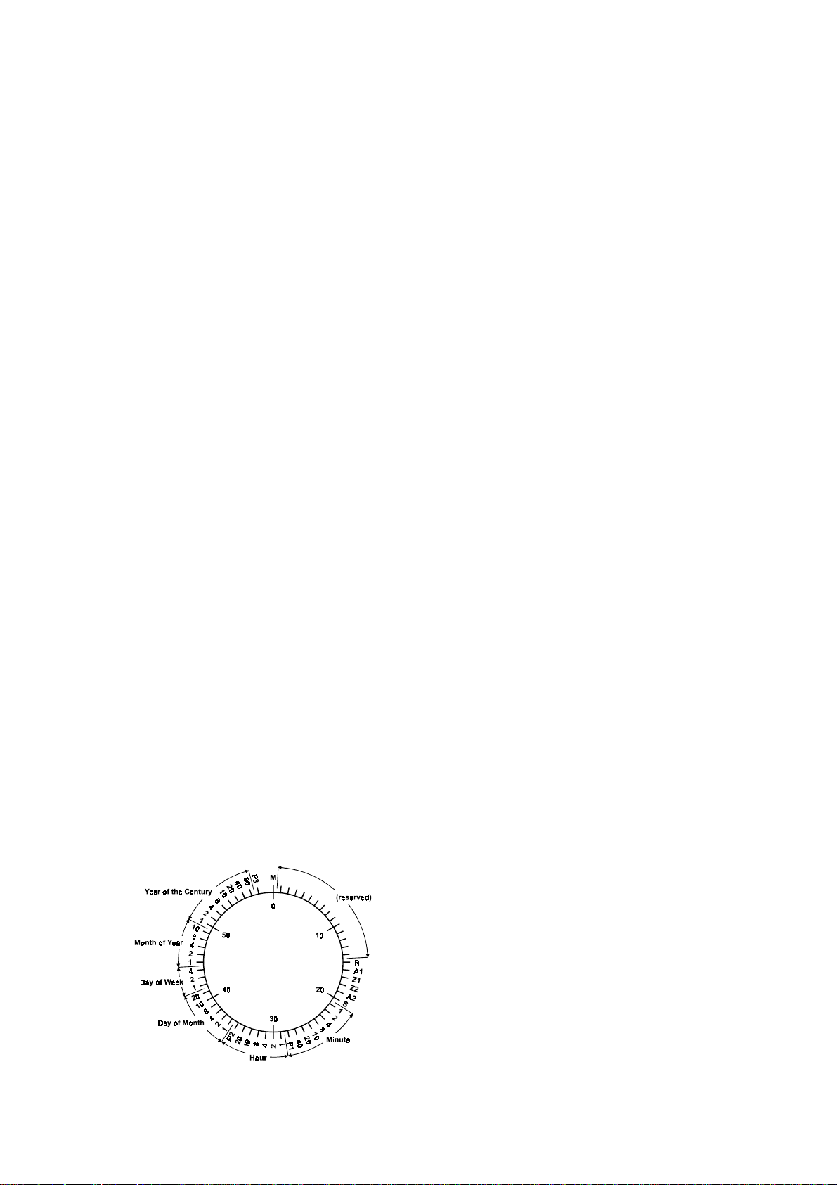
Figure: Decoding Scheme
M Start of Minute (0.1 sec)
R RF Transmission via secondary antenna
A1 Announcement of a change in daylight saving
Z1, Z2 Time zone identification
Z1,Z2 = 0,1: Daylight saving disabled (MEZ)
Z1,Z2 = 1,0: Daylight saving enabled (MESZ)
A2 Announcement of a leap second
S Start of time code information (0.2 sec)
P1, P2, P3 Even parity bits
5
Page 6

6
Page 7

DCF77C51
The radio remote clock DCF77C51 has been designed for applications where only the
serial interface is used to transmit information on date and time to other devices. The
clock has an enhanced LF receiver and is manufactured using surface mounting
technology (SMT). The electronic assembly is mounted in a plastic case with four
LEDs in the front panel which let the user monitor the clock's status.
Overview
Antenna and LF Receiver
An external ferrit antenna is used to receive the signal from DCF77. Optionally, a
weather-proof antenna is available which can be mounted outdoor. A coaxial cable
which can be up to more than 100 meters in length is used to pass the antenna's output
signal to the on-board LF receiver where it is demodulated by a synchronous detector
with automatic gain control. The demodulated time marks are fed to the clock's
microprocessor.
Microprocessor Circuit
Time marks from the receiver circuit are filtered and decoded by the microprocessor.
If no errors are detected in the current time message an additional plausibility check
against the previous time message is performed. If that plausibility check passes, too,
the real time clock on the board is adjusted corresponding to the decoded time and
date. The real time clock is read periodically and it's date and time are passed to the
serial port drivers. Additionally, the microprocessor generates output pulses when the
second or minute changes. An on-board microprocessor supervisory circuit provides a
watchdog timer which lets the microprocessor recover from malfunction, along with a
power-fail comparator which resets the microprocessor if the supply voltage drops
below a specified threshold.
Buffered Real Time Clock
If the board's power supply is turned off, a gold cap capacitor on the board lets the real
time clock keep time and status for a minimum of 48 hours (typically 180 hours). This
capacitor does not need any maintenance. Alternatively, the clock can be ordered with
a lithium battery which has 10 years of life time guaranteed.
Asynchronous Serial Port
An asynchronous serial port can be used to transmit information on date and time to
other devices. The port can be set up as either RS-232 port or 20 mA current loop.
7
Page 8

Installation
The radio remote clock has a built in AC power supply. After the power cable has been
connected, a green LED labeled Netz indicates that the clock is ready to operate. If the
antenna cable has been connected to both the antenna and the clock's BNC connector,
the brighness of the LED labeled Feldstärke reflects the signal strength of the 77.5
kHz carrier. In order to get the maximum signal, the antenna should be aligned in two
steps. First it should be turned slowly until the Feld LED is mostly dimmed. Finally
the antenna must be turned by 90° from this position to obtain maximum signal. The
antenna should be installed at least 30 cm away from the clock and from steel girders
or plates.
If the antenna is installed properly and the signal from DCF77 can be received
without strong distortions, the green LED labeled Modulation starts blinking exactly
once per second, corresponding to the time marks from DCF77. If this LED flashes
intermediately, there is some electrical noise around which prevents the microprocessor from decoding the time message. In this case, a better location for the antenna must
be found.
After reset, the red LED labeled Freilauf indicates that the clock is running on xtal
and has not synchronized with DCF77 yet. Due to the plausibility checks, it can take
up to three minutes after power-up until the clock is synchronized and this LED is
turned off. The state of this LED only changes when a new minute begins.
Frontview
8
Page 9

Serial Port
The asynchronous serial port can be configured by a DIL switch located inside the
clock's case. When the clock is beeing shipped, the levers of the DIL switch have been
set to some defaults which are marked by asterisks (*) in the tables below. If one of the
switch settings has to be changed, the upper part of the clock's case must be removed
by detaching the 4 screws located at the edges of the cover.
Serial Input and Output Drivers
The serial string generated by the microprocessor is fed into a RS-232 output driver
plus a 20mA current loop driver in parallel. If the clock is configured to send time
messages automatically once per second or once per minute, both of the outputs may
be used concurrently.
The serial input drivers need to be connected only if a serial string shall be sent on
request. Lever 10 of the DIL switch lets the user select either RS-232 input or current
loop input. It is not possible to use both the current loop input and the RS-232 input
together.
SW1-10 Input
off RS232 *
on 20mA
Both the current loop input and output can be wired for either active or passive
operation. If a current loop driver shall be operated in active mode, either -15V must
be supplied at the connector or the corresponding pin of the port can be wired to
ground An example application at the end of this manual shows how to connect the
port.
Transmission Speed
The transmission speed can by selected by levers 1 to 3 of the DIL switch. Any
commonly used speed from 600 baud through 19200 baud can be configured:
SW-1 SW-2 SW-3 Baud
on on on 600
off on on 1200
on off on 2400
off off on 4800
on on off 9600 *
off on off 19200
on off off (reserved)
off off off (reserved)
9
Page 10

Fr aming
Levers 4 and 5 of the DIL switch are used to select the framing type of the serial port:
SW-4 SW-5 Framing
on on 7E1
off on 7E2 *
on off 8N1
off off 8N2
Framing types are usually labeled with three-character abbreviations. The first character
represents the number of data bits (7 or 8), the second character indicates whether parity
checking is used or not (N=no parity, E=even parity) and the last character gives the
number of stop bits to use (1 or 2).
Output mode
The serial port sends a time string on request by incoming '?' character (ASCII code
3Fh). Additionally, a time string can be generated automatically either whenever a
new second starts or when a new minute begins. Levers 6 and 7 are used to select the
desired mode of operation:
SW-6 SW-7 String Mode
on on once per second *
off on once per minute
on off on request only
off off (reser ved)
Time Zone
Lever 8 of the DIL switch lets the user select the clock's time zone. The serial string
may either contain the Central European Time rsp. Central European Summer Time
(CET/CEST=MEZ/MESZ), or always UTC (formerly GMT).
SW1-8 Time Zone
off UTC
on MEZ/MESZ *
Pulse Outputs
Whenever a new second or minute starts, a corresponding pulse (P_SEC, P_MIN)
with a width of 200msec is generated. These pulses are made available at the DB25
connector via optocoupler outputs. The P_SEC pulse is also available with RS-232 level
(-3..12V/+3..12V). If required, Jumper JP2 must be set to activate this puls. See the
technical description and application example at the end of this manual for details.
10
Page 11

DIL-Switches
SW1-SW3 Baudrate 600/1200/2400/4800/9600/19200
SW4 - SW5 Framing 7E1 / 7E2 / 8N1 /8N2
SW6 - SW7 Output Mode per second / per minute / on request
SW8 Timezone UTC / (MESZ/MEZ)
SW9 reserved
SW10 Serial Input 20mA / RS232
framing: 7E2 / baudrate: 9600 / output mode: per second / timezone: MESZ/MEZ
* default settings:
11
Page 12

Technical Specifications
RECEIVER: Synchronous demodulator with automatic gain control
bandwidth: approx. 50Hz
ANTENNA: Active external ferrite antenna in a plastic case
Length of the cable: up to more than 100m
RF AMPLITUDE,
MODULATION: Indicated by LED
TIMECODE
CHECK: Parity and consistency checking over a period of two minutes
RF distortions indicated by both LED and a status character in
the serial output string
Without RF signal the clock runs on XTAL
with an accuracy of 10
BATTERY
BACKUP: Gold Cap or Lithium battery
when the power is turned off, the on-board RTC keeps the time
based on XTAL for more than 48 hours (gold cap) rsp. more
than 10 years (lithium battery)
-6
RELIABILITY OF
OPERATION: Microprocessor supervisory circuit provides watchdog timer,
power supply monitoring and backup-battery switchover
OUTPUT
PULSES: Optocoupler outputs (70V/20mA) provide pulses of 200msec
width whenever a new second rsp. minute begins.
P_SEC pulse with RS232-level (Jumper JP2 must be set)
ASYNCHRONOUS
SERIAL PORT: Transmission speed, framing, time zone and mode of operation
configurable by DIL switch
TRANSMISSION
SPEED: 600 through 19200 baud
FRAMING: 7E1, 7E2, 8N1 or 8N2
MODE OF
OPERATION: time string transmitted automatically once per second, once per
minute, or when a request character '?' has been received
12
Page 13

TIME ZONE: MEZ/MESZ=CET/CEST, or UTC
OUTPUT
STRING: see "Format of the Meinberg Standard Time String"
SERIAL LINE
DRIVERS: Output: RS-232 and 20mA current loop (active or passive)
Input: RS-232 or 20mA current loop (active or passive),
selectable by jumper
CONNECTORS: DB25 connector
coaxial RF connector (BNC type)
POWER
SUPPLY: 230V AC, 50Hz
-15V only when using 20mA current loop
PHYSICAL
DIMENSIONS: Rolec Technobox TBA 084
L x B x H (160mm x 81mm x 62mm)
AMBIENT
TEMPERATURE: 0 ... 50°C
HUMIDITY: max. 85 %
OPTIONS: Hardware and software modifications accordding to customer
specification
CE Label
This device conforms to the directive 89/336/EWG on the approximation of the laws of the Member States of the European Community
relating to electromagnetc compatibility.
13
Page 14

Format of the Meinberg Standard Time String
The Meinberg Standard Time String is a sequence of 32 ASCII characters starting with
the STX (start-of-text) character and ending with the ETX (end-of-text) character. The
format is:
<STX>D:dd.mm.yy;T:w;U:hh.mm.ss;uvxy<ETX>
The letters printed in italics are replaced by ASCII numbers whereas the other
characters are part of the time string. The groups of characters as defined below:
<STX> Start-Of-Text (ASCII code 02h)
dd.mm.yy the current date:
dd day of month (01..31)
mm month (01..12)
yy year of the century (00..99)
w the day of the week (1..7, 1 = Monday)
hh.mm.ss the current time:
hh hours (00..23)
mm minutes (00..59)
ss seconds (00..59, or 60 while leap second)
uv clock status characters:
u: ‘#’ clock has not synchronized after reset
‘ ‘ (space, 20h) clock has synchronized after reset
v: ‘*’ DCF77 clock currently runs on XTAL
‘ ‘ (space, 20h) DCF77 clock is sync'd with transmitter
x time zone indicator:
‘U’ UTC Universal Time Coordinated, formerly GMT
‘ ‘ MEZ European Standard Time, daylight saving disabled
‘S’ MESZ European Summertime, daylight saving enabled
y anouncement of discontinuity of time, enabled during last hour
before discontinuity comes in effect:
‘!’ announcement of start or end of daylight saving time
‘A’ announcement of leap second insertion
‘ ‘ (space, 20h) nothing announced
<ETX> End-Of-Text (ASCII code 03h)
14
Page 15

Connectors
Name Type Signal Cable
Serial Interface 25 pin SUB-D RS232 shielded data line
20mA
Pulse Outputs pulse per second
pulse per minute
Antenna BNC 77.5kHz shielded coaxial line
(RG174/RG58)
Power Supply 230V /AC power supply cord
DSUB-25 Connector Pin Assignments
1 14 P_SEC out, collect or
2 RxD in 15 P_SEC out, emitter
3 TxD out 16 P_MIN out, collect or
4 RTS (connected with CTS) 17 P_MIN out, emit ter
5 CTS (connected with RTS) 18
6 DSR (connected with DTR) 19
7 GND 20 DTR (connected wit h DSR)
8 P_SEC (RS232) 21 -act_in
9 -pass_in / +act _i n 22
10 +pass_in 23
11 curr_l oop +5V out 24 curr_l oop - 15V in
12 +pass_out 25 -act_out
13 -pas s_out / +act _out
DB25 connector, female, front view
15
Page 16

16
Page 17

Component Layout
17
Page 18

Usage of the Current Loop Interface
The current loop interface can be wired to work in one of two modes: active output
drives passive input, or passive output to active input.
Active Output to Passive Input
If the clock's current loop output shall be wired to operate as active output, a
connection from the pin labeled +pass_out to Vcc (+5V) must be provided. The pin
labeled -act_out is pulled down to the auxiliary -15V supply, which must be made
available by the user.
active current loop output with auxiliary -15V supply
If an external -15V supply is not available, the -act_out signal can be connected
directly to GND, as shown below:
active current loop output without auxiliary -15V supply
18
Page 19

Passive Output to Active Input
If a current loop output shall be wired to operate as passive output, the input wust be
wired to operate as active input. A connection from the pin labeled +pass_in to Vcc
(+5V) must be provided. The pin labeled -act_in is pulled down to the auxiliary -15V
supply, which must be made available by the user.
active current loop input with auxiliary -15V supply
If an external -15V supply is not available, the -act_in signal can be connected
directly to GND, as shown below:
active current loop input without auxiliary -15V supply
19
Page 20

 Loading...