

Page 1

Technical Information
Operating Instructions
C28COM
Driver software for
Windows 95/98® operating systems
Page 2

Impressum
Werner Meinberg
Auf der Landwehr 22
D-31812 Bad Pyrmont
Phone: ++49 52 81 - 9309-0
Fax: ++49 52 81 - 9309-30
Internet: http://www.meinberg.de
Email: info@meinberg.de
August 20, 2008
Page 3

Table of contents
Impressum ............................................................................................ 2
General Information about DCF77 ...................................................... 5
Overview C28COM ............................................................................. 6
Installation ............................................................................................ 7
Power supply .............................................................................. 7
Aligning the antenna ................................................................... 7
Pin assignment of the 9pin D-SUB ...................................................... 8
Pin assignment of the computer’s RS232 ports ................................... 8
Status LED ........................................................................................... 9
Technical specifications C28COM ...................................................... 9
Format of the Meinberg standard time string ........................... 10
Housing/Dimensions ................................................................ 11
CE Label ................................................................................... 11
Diskette with driver software ............................................................. 12
Operation under Windows95/98® ..................................................... 13
Quick installation ...................................................................... 13
Detailed installation instructions .............................................. 14
The driver software MBGTIMEMON.EXE ...................................... 15
The pull-down menu „File“ ................................................................ 16
Options...................................................................................... 16
Advanced Options ........................................................... 17
Set time only if clock synchronous ................................. 17
Synchronization radius .................................................... 17
Number of correct telegrams ........................................... 18
Activate datalogger ......................................................... 18
Delete logfiles after * days .............................................. 19
Load program at systemstart ........................................... 19
Page 4

View logfile .............................................................................. 19
Terminal.................................................................................... 20
Start/Stop timecontrol ............................................................... 20
Uninstall monitor ...................................................................... 20
Exit monitor .............................................................................. 20
Entries in the registry used by the time adjustment service ............... 21
4
Page 5
General Information about DCF77
The radio remote clocks made by Meinberg receive the signal from the long wave
transmitter DCF77. This long wave transmitter installed in Mainflingen near Frankfurt/Germany transmits the reference time of the Federal Republic of Germany. This
time reference is either the Central European Time (Mitteleuropäische Zeit, MEZ) or
the Central European Summer Time (Mitteleuropäische Sommerzeit, MESZ). The
transmitter is controlled by the atomic clock plant at the Federal Physical Technical
Institute (PTB) in Braunschweig/Germany and transmits the current time of day, date
of month and day of week in coded second pulses. Once every minute the complete
time information is available.
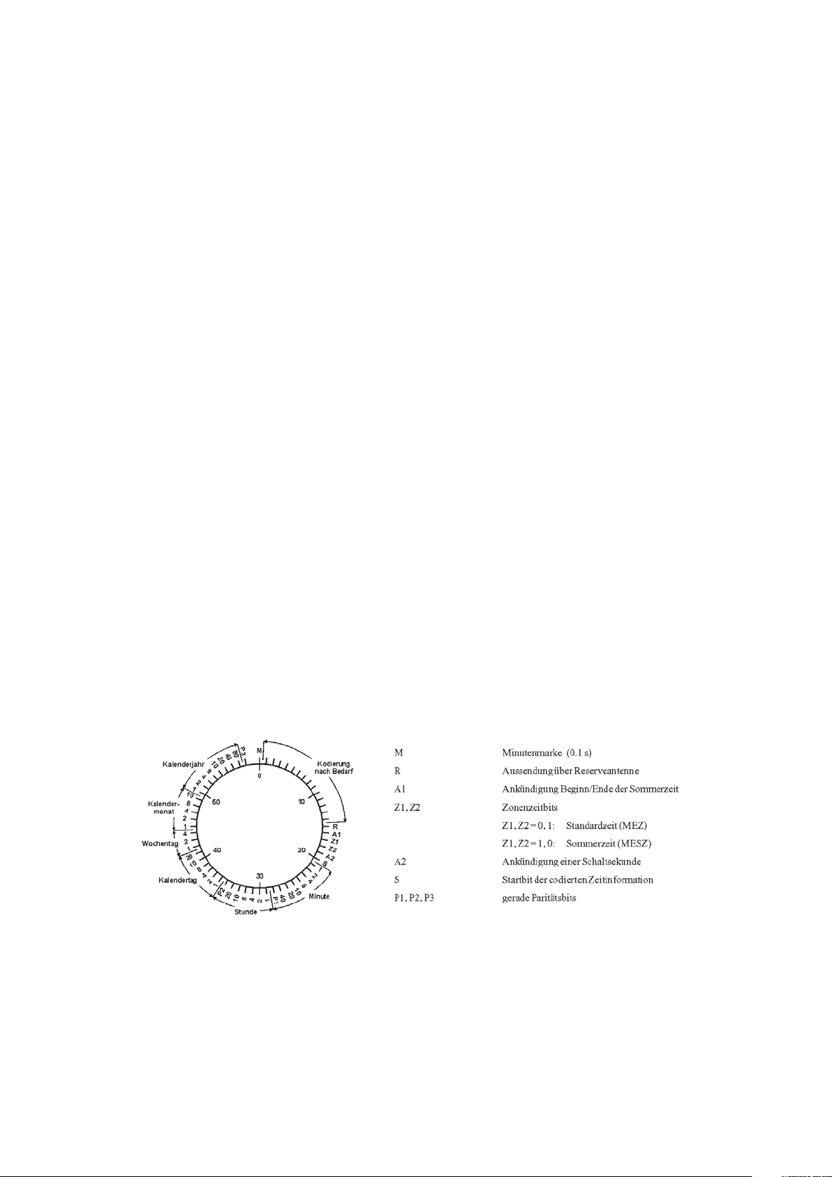
At the beginning of every second the amplitude of the high precision 77.5 kHz
carrier frequency is lowered by 75% for a period of 0.1 or 0.2 sec. The length of these
time marks represents a binary coding scheme using the short time mark for logical
zeroes and the long time mark for logical ones. The information on the current date and
time as well as some parity and status bits can be decoded from the time marks of the
15th up to the 58th second every minute. The absence of any time mark at the 59th
second of a minute signals that a new minute will begin with the next time mark.
Our radio remote clocks decode the highly accurate information on date and time
within a wide range around Germany. So some of our clocks are installed in Bilbao/
Spain as well as in the city of Umeå in northern Sweden - fully satisfying the
requirements of the users. The radio remote clocks automatically switch to summertime and back. The reception of the time information is free of charge and does not need
to be registered.
Figure: Decoding scheme
5
5
Page 6
Overview C28COM
The radio remote clock C28COM is designed to operate in conjunction with a serial
RS-232 interface of a computer. The supply voltage for the module is provided by
control signals of the COM port. Therefore no external voltage needs to be applied.
The module generates a serial Meinberg Standard String which contains informations
like date, time and status of the clock. C28COM sends this string once per second with
transmission speed 9600bd framing 7E2, see chapter „Format of the Meinberg standard time string“ for details.
An internal ferrit antenna is used to receive the signal from DCF77 and supplies it to
the on-board LF receiver where it is demodulated by a straight detector with automatic
gain control. The demodulated time marks are fed to the clock´s microprocessor for
decoding. Parity and consistency checks over a period of two minutes take care for
detecting errors in the received time telegram. The checked and decoded time is
written to the software clock and spread by the serial interface of C28COM.
C28COM includes a two-color LED which displays the demodulated DCF77 time
marks and the status of the clock.
The clock is precanned with a connection cable of two meters length and is equipped
with a 9pin D-SUB female connector (25pin on request). It is appropriated to connect
directly to the RS-232 port of a PC.
The scope of supply includes a driver software for Windows95/98® operating
systems. This program adjusts the system time of the computer and displays several
status information of the time adjustment and the clock C28COM.
Meinberg driver software for various different operating system can be found for
free download at: http://www.meinberg.de/german/sw/index.htm
Note about using the driver software: the module C28COM doesn’t
include a real time clock. After power up the time string can’t
contain the current time until first synchronization therefore. If you
are using a Meinberg driver software, the option of accepting the
time send by the DCF-clock even in case of free run should not be
active.
6
Page 7

Installation
After connecting the D-SUB connector to a RS-232 port of a computer the C28COM
is already installed. To ensure correct operation the following points have to be
considered.
Power supply
The flow control signals RTS (Request To Send) and DTR (Data Terminal Ready)
and the data signal TxD (Transmit Data) of the connected PC port are used to supply
the power needed by C28COM.
After powering up the computer the control signals do not conduct the required
potential. For this reason the C28COM is not ready to operate until the driver
software is started. The software switches the control signals to the correct state.
If the user wants to write his own software for evaluating the serial time string, he
has to make sure, that the software switches the flow control signals RTS and DTR of
the computer into the ‘OFF’-state. These lines must have a positive voltage relating to
the reference potential (GND).
Aligning the antenna
It is important that the position of the module and it’s integrated antenna ensures
optimal conditions for receiption of the DCF77-signal. The antenna should be aligned
with the arrow symbol printed on the case pointing to the direction of the transmitter
(Frankfurt am Main). A distance of several meters is recommended to all TVs or
computer monitors, computers or processorboards. The antenna should have a minimum distance of 30 centimeters from solid steel.
The alignment of the Antenna can be done with the help of the integrated LED. Like
described in chapter „General Information about DCF77“, the DCF77 protocol can
only be decoded if all time marks can be received correctly without interfering pulses.
Therefore a LED switched off strictly once per second (not in second 59) indicates
good conditions of receiption.
7
Page 8

Pin assignment of the 9pin D-SUB
The assignment of the module’s D-SUB connector allows the connection directly to a
RS-232 port of a personal computer. If a longer cable is needed it is possible to
lengthen it by using a 1:1 cable. The maximum length depends on the RS-232-driver
circuit of the computer and can’t be specified generally for this reason.
Pin assignment of the computer’s RS-232 ports
The serial RS-232 ports of a computer are assigned as follows:
13
5
9
6
1
9-pin D-SUB Connector 25-pin D-SUB Connector
Pin Name Description Pin Name Description
1 CD Carrier Detect 1 Shield Shield Ground
2 RxD Receive Data 2 TxD Transmit Data
3 TxD Transmit Data 3 RxD Receive Data
4 DTR Data Terminal Ready 4 RTS Request to Send
5 GN D System Ground 5 CTS Clear to Send
6 DS R Data Set Ready 6 DSR Data Set Ready
7 RT S Re que st to Se nd 7 G N D S ystem G round
8 CTS Clear to Send 8 C D C arrier Detect
9 RI Ring Indicator 20 DTR Data Terminal Ready
22 RI Ring Indicator
25
14
1
8
Page 9

Status LED
The integrated two-color LED displays the synchronization status and the demodulated time marks of the module C28COM. A red LED indicates a free running clock
while a green shining LED shows the user that the clock is already synchronized to
DCF77. A correctly demodulated time mark turns off the respective shining LED for
100 msec or 200 msec.
Technical specifications C28COM
RECEIVER: Narrowband straight receiver with automatic gain control
bandwidth approx. 50 Hz, gain control approx. 90 dB
internal ferrite antenna
MODULATION: demodulated time marks displayed by LED
TIMECODE
CHECK: multiple software checks of the incoming timecode
parity and consistency check over a period of two minutes
RUNNING
ON CRYSTAL: RF signal distortions causes the clock running on crystal with an
accuracy of +/- 20 ppm
indicated by LED and status character of serial time string
RELIABILITY
OF OPERATION: a watchdog lets the microprocessor recover from malfunction.
SERIAL
INTERFACE: one asynchronous serial interface (RS-232)
POWER
REQUIREMENTS: via the RS-232 flow control signals RTS and DTR and the data
signal TxD
load: RTS, DTR approx. 3mA each
TxD approx. 2.8mA
HOUSING: Unbreakable plastic case, 60 mm x 50 mm x 20 mm
AMBIENT
TEMPERATURE: -20 ... 65°C
HUMIDITY: max. 85 %
9
Page 10

Format of the Meinberg standard time string
The Meinberg standard time string is a sequence of 32 ASCII characters starting with
the STX (start-of-text) character and ending with the ETX (end-of-text) character. The
format is:
<STX>D:dd.mm.yy;T:w;U:hh.mm.ss;uvxy<ETX>
The letters printed in italics are replaced by ASCII numbers whereas the other characters are part of the time string. The groups of characters as defined below:
<STX> Start-Of-Text (ASCII code 02h)
dd.mm.yy the current date:
dd day of month (01..31)
mm month (01..12)
yy year of the century (00..99)
w the day of the week (1..7, 1 = Monday)
hh.mm.ss the current time:
hh hours (00..23)
mm minutes (00..59)
ss seconds (00..59, or 60 while leap second)
uv clock status characters:
u: ‘#’ clock has not synchronized after reset
‘ ‘ (space, 20h) clock has synchronized after reset
v: different for DCF77 or GPS receivers:
‘*’ DCF77 clock currently runs on XTAL
GPS receiver has not checked its position
‘ ‘ (space, 20h) DCF77 clock is sync'd with transmitter
GPS receiver has determined its position
x time zone indicator:
‘U’ UTC Universal Time Coordinated, formerly GMT
‘ ‘ MEZ European Standard Time, daylight saving disabled
‘S’ MESZ European Summertime, daylight saving enabled
y anouncement of discontinuity of time, enabled during last hour
before discontinuity comes in effect:
‘!’ announcement of start or end of daylight saving time
‘A’ announcement of leap second insertion
‘ ‘ (space, 20h) nothing announced
<ETX> End-Of-Text (ASCII code 03h)
10
Page 11

Housing/Dimensions
E
e
a
60.0 mm
DCF 77-RADIO CLOCK
C28COM
DCF-Transmitter (Frankfurt am Main)
FUNKUHREN
Auf der Landwehr 22
31812 Bad Pyrmont
D-
Germany
email: info@meinberg.de
internet: www.meinberg.de
MOD.
CE Label
m
m
0
.
0
5
m
m
0
.
0
2
This device conforms to the directive 89/336/
approximation of the laws of the Member Stat
Community relating to electromagnetc comp
11
Page 12

Diskette with driver software
12
Page 13

Operation under Windows95/98
®
The driver software reads the time and status information send by C28COM and
adjusts the system time of Windows9x to this reference. Besides C28COM, every
Meinberg clock sending a serial Meinberg standard time string once per second can be
used as a reference for the driver.
In addition the program monitors the operation status of the radio clock and the time
service.
Quick installation
The following steps are required for installation of the driver software:
- start installation program SETUP.EXE
- select directory for installation
- select program folder
- start program MBGTIMEMON.EXE
- select language
- set parameters (RS-232-port, synchronization radius...)
- check status display in driver software
13
Page 14

Detailed installation instructions
If the program MBGTIMEMON.EXE is started for the first time, the desired language has to be selected:
After choosing the language, the following dialog field of the installation routine
appears:
The driver software reads the reference time of the C28COM by using one of the
computer’s RS-232-interfaces. The ports COM1 to COM4, standard transmision
speeds of 2400bd to 19200bd and several different framings can be selected. In
addition, the type of the serial time telegram can be changed to „Interflex“ or „SAT“ if
necessary. The parameters shown above must be selected for correct operation of
the driver software in conjunction with C28COM. By using button „Install“ all
entries in the Windows registry are made and the driver software starts. Submenu
„Terminal“ of Menu „File“ starts a program for testing if the time telegrams are send
once per second by the clock at the specified COM-port (with the specified parameters).
Important: after installation of the driver software, the time service is not
active automatically and the system time is not adjusted therefore. You have to
select the option „Start timecontrol“ in menu „File“ to start the time service.
14
Page 15

The driver software MBGTIMEMON.EXE
The main tasks of program MBGTIMEMON.EXE are to adjust the system time and to
monitor the status of the computer and the radio clock.
The above part of the main window shows the current system time, the time of the
external reference, the result of the last comparison of these times and magnitude and
time of the last correction of the system time. Informations of the connected radio
clock are shown below.
When clicking on the „minimize“ button the driver software is minimized to the
Windows TrayIconBar and the progam logo is displayed in the symbol bar. The right
mouse button may be used to open a menu for starting or stopping the monitor.
15
Page 16

The pull-down menu „File“
Use the File menu to set various parameters or to initiate various tasks. The submenus
are described below.
Options
Menu Options must be opened to change the parameters of the serial port or the
„Advanced Options“.
16
Page 17

Advanced Options
This menu may be used to change settings concerning the behaviour of the time
service. These options are described below.
Set time only if clock synchronous
If this option is active, the system time is adjusted only if the radio clock is synchronized by DCF77. If the clock enters the free running mode during operation, the system
time is not adjusted until C28COM is synchronous again.
As described in chapter „Overview C28COM“, this option should be active.
Synchronization radius
Once per second the time adjustment service calculates the difference between system
time and the reference time send by the radio clock. If the magnitude of this difference
is less than the value defined by this parameter, the system time will not be adjusted.
The „Synchronization radius“ is set to 300 msec per default. This results in a time
adjustment only if a difference of more than +/- 0,3 seconds is calculated.
17
Page 18

Number of correct telegrams
Whenever the time adjustment service reads the reference time from the radio clock,
transmission errors may occur which could lead to a faulty time. The parameter
„Number of correct telegrams“ specifies how many correct time telegrams must be
received in succession before the time adjustment service accepts the current telegram.
In addition, the service makes a plausibility check of each single telegram and of the
given number of consecutive telegrams before accepting the information sent by the
radio clock and adjusting the system time.
Activate datalogger
The datalogger may be used to record the activities of the time adjustment service in a
data file. Seperate files will be generated for each day which are stored in the
installation directory of the driver software. The adjustments of the system time and
the status of the radio clock are stored in the data file. The times given in the logfile are
based on UTC (Universal Time Coordinated).
The name of a data file has the following structure:
YYMMDD.TXT YY: year
MM: month
DD: day
The file named „010410.txt“ would be the logfile of April, 10th, 2001 for example.
Extract from a logfile:
C28COM LOGFILE
10.04.01
07:00:47 Start monitor
07:00:47 Reference time not valid
07:03:00 clock synchronous
07:05:52,990 set time: 07:00:53,00 corr: 0,01 Sek
07:55:53,980 set time: 07:01:54,50 corr: 0,07 Sek
08:02:04 Exit monitor
18
Page 19

Delete logfiles after * days
This option defines how long logfiles will be stored on the harddisk. The program
MBGTIMEMON.EXE checks the age of the logfiles periodically and deletes files that
are older than the number of days given by this option.
Load program at systemstart
The driver software will be activated automatically during the next start of the Windows operating system if this checkbox is marked.
View logfile
Submenu View logfile opens a window showing the current logfile. All other files
may be displayed by selecting them from the list at the bottom of the window. Using
the „Ref“ button causes an update of the present-day logfile, using the „Del“ button
deletes the displayed file.
19
Page 20

Terminal
Submenu Terminal opens a window displaying the time telegrams received by the
time service. If no telegram can be received, check the settings of the RS-232 interface
connected to C28COM for: string type Standard Meinberg, baudrate 9600bd, framing 7E2.
Start/Stop timecontrol
The adjustment of the system time may be activated and deactivated. If the program is
minimized in the TrayIconBar, the program logo will be crossed out if the time service
is inactive.
Uninstall monitor
This submenu delets all entries made in the Windows registry. The program folder of
the driver software with its files will not be deleted.
Exit monitor
The control of the system time will be stopped and the driver software will be
terminated when clicking on this submenu.
20
Page 21

Entries in the registry used by the time adjustment service
The driver software adds some entries to the Windows registry under the path:
HKEY_CURRENT_USER\SOFTWARE\
The following entries are stored under the key C28COM:
Active Status of the driver software at last program termination
Autostart Loading of driver at system start
Comport Number of COM-port (1-4)
DLogger Activate datalogger
FileDelDelay Maximum age of logfiles
Installed Program has been installed
Language Selected language 0 = German 1 = English
NumKorTel Number of correct telegrams
Sync Set time only if clock synchronous 0=deaktivated 1=aktivated
SyncRadius Synchronization radius
21
Page 22

 Loading...