

Page 1
Page 2

RedLab TC
USB-based 8-Channel Thermocouple Input
Module
User's Guide
Document Revision 1.4 E, January, 2008
© Copyright 2008, Meilhaus Electronic
Page 3

Imprint
User’s Guide RedLab® Series
Document Revision 1.4 E
Revision Date: January 2008
Meilhaus Electronic GmbH
Fischerstraße 2
D-82178 Puchheim near Munich, Germany
http://www.meilhaus.de
© Copyright 2008 Meilhaus Electronic GmbH
All rights reserved. No part of this publication may be reproduced, stored in a retrieval system, or
transmitted, in any form by any means, electronic, mechanical, by photocopying, recording, or
otherwise without the prior written permission of Meilhaus Electronic GmbH.
Important note:
All the information included in this user’s gide were put together with utmost care and to best
knowledge. However, mistakes may not have been erased completely.
For this reason, the firm Meilhaus Electronic GmbH feels obliged to point out that they cannot be take
on neither any warranty (apart from the claims for warranty as agreed) nor legal responsibility or
liability for consequences caused by incorrect instructions.
We would appreciate it if you inform us about any possible mistakes.
The trademark Personal Measurement Device, TracerDAQ, Universal Library, InstaCal, Harsh
Environment Warranty, Measurement Computing Corporation, and the Measurement Computing logo
are either trademarks or registered trademarks of Measurement Computing Corporation.
Windows, Microsoft, and Visual Studio are either trademarks or registered trademarks of Microsoft
Corporation.
LabVIEW is a trademark of National Instruments.
CompactFlash is a registered trademark of SanDisk Corporation.
XBee is a trademark of MaxStream, Inc.
All other trademarks are the property of their respective owners.
3
Page 4

Table of Contents
Preface
About this User’s Guide .......................................................................................................................6
What you will learn from this user’s guide.........................................................................................................6
Conventions in this user’s guide.........................................................................................................................6
Where to find more information.........................................................................................................................6
Chapter 1
Introducing the RedLab TC..................................................................................................................7
Overview: RedLab TC features..........................................................................................................................7
RedLab TC block diagram..................................................................................................................................8
Software features................................................................................................................................................8
Connecting a RedLab TC to your computer is easy ...........................................................................................9
Chapter 2
Installing the RedLab TC....................................................................................................................10
What comes with your RedLab TC shipment? .................................................................................................10
Hardware .........................................................................................................................................................................10
Additional documentation................................................................................................................................................10
Unpacking the RedLab TC...............................................................................................................................11
Installing the software ......................................................................................................................................11
Installing the RedLab TC..................................................................................................................................11
Configuring the RedLab TC .............................................................................................................................12
Calibrating the RedLab TC...............................................................................................................................12
Chapter 3
Sensor Connections ...........................................................................................................................13
Screw terminal pin out......................................................................................................................................13
Thermocouple input terminals (C0H/C0L to C7H/C7L) .................................................................................................14
Ground terminals (GND) .................................................................................................................................................14
Power terminals (+5V).....................................................................................................................................................14
Digital terminals (DIO0 to DIO7)....................................................................................................................................14
CJC sensors......................................................................................................................................................................14
Thermocouple connections...............................................................................................................................15
Wiring configuration........................................................................................................................................................15
Digital I/O connections.....................................................................................................................................16
Chapter 4
Functional Details ...............................................................................................................................17
Thermocouple measurements ...........................................................................................................................17
Cold junction compensation (CJC)..................................................................................................................................17
Data linearization.............................................................................................................................................................17
Open-thermocouple detection (OTD) ..............................................................................................................................17
USB connector..................................................................................................................................................18
LED ..................................................................................................................................................................18
Power................................................................................................................................................................18
Chapter 5
Specifications......................................................................................................................................19
Analog input .....................................................................................................................................................19
Channel configurations.....................................................................................................................................19
Accuracy...........................................................................................................................................................20
Thermocouple measurement accuracy.............................................................................................................................20
Throughput rate ................................................................................................................................................20
4
Page 5

RedLab TC User's Guide
Digital input/output...........................................................................................................................................21
Memory ............................................................................................................................................................21
Microcontroller.................................................................................................................................................21
USB +5V voltage .............................................................................................................................................21
Power................................................................................................................................................................22
USB specifications ...........................................................................................................................................22
Environmental ..................................................................................................................................................22
Mechanical .......................................................................................................................................................22
Screw terminal connector type and pin out.......................................................................................................22
Screw terminal pin out.....................................................................................................................................................23
5
Page 6
Preface
About this User’s Guide
What you will learn from this user’s guide
This user’s guide explains how to install, configure, and use the RedLab TC so that you get the most out of its
USB-based temperature measurement features.
This user’s guide also refers you to related documents available on our web site, and to technical support
resources.
Conventions in this user’s guide
For more information on …
Text presented in a box signifies additional information and helpful hints related to the subject matter you are
reading.
Caution! Shaded caution statements present information to help you avoid injuring yourself and others,
damaging your hardware, or losing your data.
<#:#> Angle brackets that enclose numbers separated by a colon signify a range of numbers, such as those assigned
to registers, bit settings, etc.
bold text Bold text is used for the names of objects on the screen, such as buttons, text boxes, and check boxes. For
example:
1. Insert the disk or CD and click the OK button.
italic text Italic text is used for the names of manuals and help topic titles, and to emphasize a word or phrase. For
example:
The InstaCal installation procedure is explained in the Quick Start Guide.
Never touch the exposed pins or circuit connections on the board.
Where to find more information
The following electronic documents provide helpful information relevant to the operation of the RedLab TC.
The Quick Start Guide is available on our RedLab CD in the root directory.
The Guide to Signal Connections is available on our RedLab CD under „ICalUL\Documents“.
The Universal Library User's Guide is available on our RedLab CD under „ICalUL\Documents“.
The Universal Library Function Reference is available on our RedLab CD under „ICalUL\Documents“.
The Universal Library for LabVIEW
„ICalUL\Documents“.
™
User’s Guide is available on our RedLab CD under
6
Page 7

Chapter 1
Introducing the RedLab TC
Overview: RedLab TC features
This user's guide contains all of the information you need to connect the RedLab TC to your computer and to
the signals you want to measure.
The RedLab TC is a USB 2.0 full-speed, thermocouple input module that is supported under popular Microsoft
Windows
The RedLab TC provides eight differential thermocouple input channels. Eight independent, TTL-compatible
digital I/O channels are provided to monitor TTL-level inputs, communicate with external devices, and to
generate alarms. The digital I/O channels are software programmable for input or output.
With the RedLab TC, you can take measurements from type J, K, R, S, T, N, E, and B thermocouples.
The RedLab TC provides two integrated cold junction compensation (CJC) sensors for thermocouple
measurements.
An open thermocouple detection feature lets you detect a broken thermocouple. An on-board microprocessor
automatically linearizes the measurement data.
The RedLab TC is a standalone plug-and-play module which draws power from the USB cable. No external
power supply is required. All configurable options are software programmable.
®
operating systems. The RedLab TC is fully compatible with both USB 1.1 and USB 2.0 ports.
®
The RedLab TC is fully software calibrated.
7
Page 8
RedLab TC User's Guide Introducing the RedLab TC
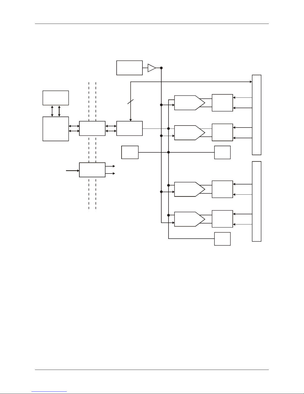
RedLab TC block diagram
RedLab TC functions are illustrated in the block diagram shown here.
Precision
5V Ref.
DIO
USB
USB
Micro
USB
+5V
I/O
Isolator
Isolated
DC/DC
500 V
Isolation
Barrier
8
Isolated
Micro
Te mp
sensor
(+12)
(-12)
Figure 1. RedLab TC functional block diagram
SPI
24-bit A/D
(CH0, CH1)
24-bit A/D
(CH2, CH3)
24-bit A/D
(CH4, CH5)
24-bit A/D
(CH6, CH7)
Input
mux.
Input
mux.
CJC
CH0-3
Input
mux.
Input
mux.
CJC
CH4-7
Screw terminalScrew terminalScrew terminal
Software features
For information on the features of InstaCal and the other software included with your RedLab TC, refer to the
Quick Start Guide that shipped with your device. The Quick Start Guide is also available in PDF on our RedLab
CD (root directory).
8
Page 9

RedLab TC User's Guide Introducing the RedLab TC
Connecting a RedLab TC to your computer is easy
Installing a data acquisition device has never been easier.
The RedLab TC relies upon the Microsoft Human Interface Device (HID) class drivers. The HID class
drivers ship with every copy of Windows that is designed to work with USB ports. We use the Microsoft
HID because it is a standard, and its performance delivers full control and maximizes data transfer rates for
your RedLab TC. No third-party device driver is required.
The RedLab TC is plug-and-play. There are no jumpers to position, DIP switches to set, or interrupts to
configure.
You can connect the RedLab TC before or after you install the software, and without powering down your
computer first. When you connect an HID to your system, your computer automatically detects it and
configures the necessary software. You can connect and power multiple HID peripherals to your system
using a USB hub.
You can connect your system to various devices using a standard four-wire cable. The USB connector
replaces the serial and parallel port connectors with one standardized plug and port combination.
You do not need a separate power supply module. The USB automatically delivers the electrical power
required by each peripheral connected to your system.
Data can flow two ways between a computer and peripheral over USB connections.
9
Page 10

Installing the RedLab TC
What comes with your RedLab TC shipment?
The following items are shipped with the RedLab TC.
Hardware
RedLab TC
Chapter 2
USB cable (2 meter length)
Additional documentation
In addition to this hardware user's guide, you should also receive the Quick Start Guide (available on our
RedLab CD (root directory)). This booklet supplies a brief description of the software you received with your
RedLab TC and information regarding installation of that software. Please read this booklet completely before
installing any software or hardware.
10
Page 11

RedLab TC User's Guide Installing the RedLab TC
Unpacking the RedLab TC
As with any electronic device, you should take care while handling to avoid damage from static
electricity. Before removing the RedLab TC from its packaging, ground yourself using a wrist strap or by
simply touching the computer chassis or other grounded object to eliminate any stored static charge.
If your RedLab TC is damaged, notify Meilhaus Electronic immediately by phone, fax, or e-mail. For
international customers, contact your local distributor where you purchased the RedLab TC.
Phone: +49 (0) 89/8901660
Fax: +49 (0) 89/89016628
E-Mail: support@meilhaus.com
Installing the software
Refer to the Quick Start Guide for instructions on installing the software Guide (available on our RedLab CD
(root directory)).
Installing the RedLab TC
To connect the RedLab TC to your system, turn your computer on, and connect the USB cable to a USB port on
your computer or to an external USB hub that is connected to your computer. The USB cable provides power
and communication to the RedLab TC.
When you connect the RedLab TC (follow illustrations: USB-TC) for the first time, a
popup balloon (Windows XP) or dialog (other Windows versions) opens as the RedLab TC is detected.
When this balloon or dialog closes, the installation is complete. The
This indicates that communication is established between the RedLab TC and your computer.
Caution! Do not disconnect any device from the USB bus while the computer is communicating with the
RedLab TC, or you may lose data and/or your ability to communicate with the RedLab TC.
If the LED turns off
If the LED is lit but then turns off, the computer has lost communication with the RedLab TC. To restore
communication, disconnect the USB cable from the computer, and then reconnect it. This should restore
communication, and the LED should turn back on.
USB LED should flash and then remain lit.
Found New Hardware
11
Page 12

RedLab TC User's Guide Installing the RedLab TC
Configuring the RedLab TC
All hardware configuration options on the RedLab TC are programmable with software. Use InstaCal to set the
thermocouple type for each channel pair. Configuration options are stored on the RedLab TC 's isolated
microcontroller in EEPROM, which is non-volatile memory on the RedLab TC module. Configuration options
are loaded on power up. The factory default configuration is Type J thermocouple.
Allow the RedLab TC to warm up for 30 minutes after powering up before taking measurements. This warm up
time minimizes thermal drift and achieves the specified rated accuracy of measurements.
Calibrating the RedLab TC
The RedLab TC is fully calibrated via InstaCal. Allow a 30 minute warm up before calibrating.
12
Page 13

Chapter 3
Sensor Connections
The RedLab TC supports type J, K, R, S, T, N, E, and B thermocouples.
Thermocouple selection
The thermocouple type you select will depend on your application needs. Review the temperature ranges and
accuracies of each type to determine which is best suited for your application.
Screw terminal pin out
The RedLab TC has four rows of screw terminals — two rows on the top edge of the housing, and two rows on
the bottom edge. Each row has 26 connections. Between each bank of screw terminals are two integrated CJC
sensors used for thermocouple measurements. Signals are identified in Figure 2.
RSVD
27 RSVD
28 GND
29 C7L
30 C7H3132 NC
6
RSVD
RSVD
33 C6L
34 C6H
35 NC
36
37
CJC SensorCJC Sensor
11
10
RSVD
38 GND
39 C5L
40 C5H4142 NC
16
RSVD
43 C4L
44 C4H
45 NC4647 +5V
48 GND
49 DIO7
50 DIO6
51 DIO5
52 DIO4
20
RSVD 1
NC 2
C0H 3
C0L 4
NC 5
C1H 7
C1L 8
GND 9
RSVD
RSVD
NC 12
C2H 13
C2L 14
NC 15
C3H 17
C3L 18
GND 19
+5V 21
RSVD
RSVD
GND 22
RSVD
Figure 2. RedLab TC screw terminal pin numbers
13
DIO0 23
DIO1 24
DIO2 25
DIO3 26
Page 14

RedLab TC User's Guide Sensor Connections
Table 3-1. RedLab TC screw terminal descriptions
Pin Signal Name Pin Description Pin Signal Name Pin Description
1 RSVD Reserved, Do Not Use 27 RSVD Reserved, Do Not Use
2 NC Not connected 28 GND Ground
3 C0H CH0 sensor input (+) 29 C7L
4 C0L
5 NC Not connected 31 RSVD Reserved, Do Not Use
6 RSVD Reserved, Do Not Use 32 NC Not connected
7 C1H CH1 sensor input (+) 33 C6L
8 C1L
9 GND Ground 35 NC Not connected
10 RSVD Reserved, Do Not Use 36 RSVD Reserved, Do Not Use
11 RSVD Reserved, Do Not Use 37 RSVD Reserved, Do Not Use
12 NC Not connected 38 GND Ground
13 C2H CH2 sensor input (+) 39 C5L
14 C2L
15 NC Not connected 41 RSVD Reserved, Do Not Use
16 RSVD Reserved, Do Not Use 42 NC Not connected
17 C3H CH3 sensor input (+) 43 C4L
18 C3L
19 GND Ground 45 NC Not connected
20 RSVD Reserved, Do Not Use 46 RSVD Reserved, Do Not Use
21 +5V +5V output 47 +5V +5V output
22 GND Ground 48 GND Ground
23 DIO0 Digital Input/Output 49 DIO7 Digital Input/Output
24 DIO1 Digital Input/Output 50 DIO6 Digital Input/Output
25 DIO2 Digital Input/Output 51 DIO5 Digital Input/Output
26 DIO3 Digital Input/Output 52 DIO4 Digital Input/Output
CJC sensor
CH0 sensor input (
CH1 sensor input (
CH2 sensor input (
CH3 sensor input (
-)
-)
-)
-)
30 C7H CH7 sensor input (+)
34 C6H CH6 sensor input (+)
40 C5H CH5 sensor input (+)
44 C4H CH4 sensor input (+)
CJC sensor
CH7 sensor input (
CH6 sensor input (
CH5 sensor input (
CH4 sensor input (
-)
-)
-)
-)
Use 16 AWG to 30 AWG wire for your signal connections.
Tighten screw terminal connections
When making connections to the screw terminals, be sure to tighten the screw until tight. Simply touching the
top of the screw terminal is not sufficient to make a proper connection.
Thermocouple input terminals (C0H/C0L to C7H/C7L)
You can connect up to eight thermocouples to the differential sensor inputs (C0H/C0L to C7H/C7L). The
RedLab TC supports type J, K, R, S, T, N, E, and B thermocouples.
Ground terminals (GND)
The six analog ground terminals (GND) provide a common ground for the input channels and DIO bits and are
isolated (500 VDC) from the USB GND.
Power terminals (+5V)
The two +5V terminals are isolated (500 VDC) from the USB +5V.
Digital terminals (DIO0 to DIO7)
You can connect up to eight digital I/O lines to the screw terminals labeled DIO0 to DIO7. Each terminal is
software configurable for input or output.
CJC sensors
The RedLab TC has two built in high-resolution temperature sensors. One sensor is located on the right side of
the package, and one sensor is located at the left side.
14
Page 15

RedLab TC User's Guide Sensor Connections
Thermocouple connections
A thermocouple consists of two dissimilar metals that are joined together at one end. When the junction of the
metals is heated or cooled, a voltage is produced that correlates to temperature.
The RedLab TC makes fully differential thermocouple measurements without the need of ground-referencing
resistors. A 32-bit floating point value in either a voltage or temperature format is returned by software. An
open thermocouple detection feature is available for each analog input which automatically detects an open or
broken thermocouple.
Use InstaCal to select the thermocouple type (J, K, R, S, T, N, E, and B) and one or more sensor input channels
to connect the thermocouple.
Wiring configuration
Connect the thermocouple to the RedLab TC using a differential configuration, as shown in Figure 3.
Figure 3. Typical thermocouple connection
Connect thermocouples to the RedLab TC such that they are floating with respect to GND (pins 9, 19, 28, 38).
The RedLab TC
GND pins are isolated from earth ground, so connecting thermocouple sensors to voltages
referenced to earth ground is permissible as long as the isolation between the GND pins (9, 19, 28, 38) and earth
ground is maintained.
When thermocouples are attached to conductive surfaces, the voltage differential between multiple
thermocouples must remain within ±1.4 V. For best results, we recommend the use of insulated or ungrounded
thermocouples when possible.
Maximum input voltage between analog input and ground
The absolute maximum input voltage between an analog input and the isolated GND pins is ±25 VDC when the
RedLab TC is powered on, and ±40 VDC when the RedLab TC is powered off.
If you need to increase the length of your thermocouple, use the same type of thermocouple wires to minimize
the error introduced by thermal EMFs.
15
Page 16

RedLab TC User's Guide Sensor Connections
Digital I/O connections
You can connect up to eight digital I/O lines to the screw terminals labeled DIO0 to DIO7. You can configure
each digital bit for either input or output. All digital I/O lines are pulled up to +5V with a 47 K ohm resistor
(default). You can request the factory to configure the resistor for pull-down to ground if desired.
When you configure the digital bits for input, you can use the RedLab TC digital I/O terminals to detect the
state of any TTL-level input. Refer to the schematic shown in Figure 4. If you set the switch to the +5V input,
DIO0 reads TRUE (1). If you move the switch to GND, DIO0 reads FALSE (0).
DIO0
+5V+GND
Figure 4. Schematic showing switch detection by digital channel DIO0
Caution! All ground pins on the RedLab TC (pins 9, 19, 28, 38) are isolated from earth ground. If a
connection is made to earth ground when using digital I/O and conductive thermocouples, the
thermocouples are no longer isolated. In this case, thermocouples must not be connected to any conductive
surfaces that may be referenced to earth ground
For general information regarding digital signal connections and digital I/O techniques, refer to the Guide to
Signal Connections (available on our RedLab CD under „ICalUL\Documents“).
16
Page 17

Chapter 4
Functional Details
Thermocouple measurements
A thermocouple consists of two dissimilar metals that are joined together at one end. When the junction of the
metals is heated or cooled, a voltage is produced that correlates to temperature.
The RedLab TC hardware level-shifts the thermocouple’s output voltage into the A/D’s common mode input
range by applying +2.5 V to the thermocouple’s low side at the C#L input. Always connect thermocouple
sensors to the RedLab TC in a floating fashion. Do not attempt to connect the thermocouple low side C#L to
GND or to a ground referencing resistor.
Cold junction compensation (CJC)
When you connect the thermocouple sensor leads to the sensor input channel, the dissimilar metals at the
RedLab TC terminal blocks produce an additional thermocouple junction. This junction creates a small voltage
error term which must be removed from the overall sensor measurement using a cold junction compensation
technique. The measured voltage includes both the thermocouple voltage and the cold junction voltage. To
compensate for the additional cold junction voltage, the RedLab TC subtracts the cold junction voltage from the
thermocouple voltage.
The RedLab TC has two high-resolution temperature sensors that are integrated into the design of the RedLab
TC. One sensor is located on the right side of the package, and one sensor is located at the left side. The CJC
sensors measure the average temperature at the terminal blocks so that the cold junction voltage can be
calculated. A software algorithm automatically corrects for the additional thermocouples created at the terminal
blocks by subtracting the calculated cold junction voltage from the analog input's thermocouple voltage
measurement.
Increasing the thermocouple length
If you need to increase the length of your thermocouple, use the same type of thermocouple wires to minimize
the error introduced by thermal EMFs.
Data linearization
After the CJC correction is performed on the measurement data, an on-board microcontroller automatically
linearizes the thermocouple measurement data using National Institute of Standards and Technology (NIST)
linearization coefficients for the selected thermocouple type.
The measurement data is then output as a 32-bit floating point value in the configured format (voltage or
temperature).
Open-thermocouple detection (OTD)
The RedLab TC is equipped with an open-thermocouple detection for each analog input channel. With OTD,
any open-circuit or short-circuit condition at the thermocouple sensor is detected by the software. An open
channel is detected by driving the input voltage to a negative value outside the range of any thermocouple
output. The software recognizes this as an invalid reading and flags the appropriate channel. The software
continues to sample all channels when OTD is detected.
17
Page 18

RedLab TC User's Guide Functional Details
Input leakage current
With open-thermocouple detection enabled, 105 nA (max.) of input leakage current is injected into the
thermocouple. This current can cause an error voltage to develop across the lead resistance of the thermocouple
that is indistinguishable from the thermocouple voltage you are measuring. You can estimate this error voltage
with the following formula:
error voltage = resistance of the thermocouple x 105 nA
To reduce the error, reduce the length of the thermocouple to lower its resistance, or lower the AWG of the wire
by using a wire with a larger diameter. With open-thermocouple detection disabled, 30 nA (max.) of input
leakage current is injected into the thermocouple.
USB connector
The USB connector provides +5V power and communication. No external power supply is required.
LED
The LED indicates the communication status of the RedLab TC. It uses up to 5 mA of current. The table below
defines the function of the RedLab TC LED.
LED Illumination
LED
Illumination
Steady green The RedLab TC is connected to a computer or external USB hub.
Pulsing green Data is being transferred.
Indication
Upon connection, the LED should flash three times and then remain lit (indicates a successful
installation).
Power
The two +5V terminals are isolated (500 VDC) from the USB +5V.
Caution! Each +5V terminal is an output. Do not connect to an external power supply or you may damage
the RedLab TC and possibly the computer.
18
Page 19

Chapter 5
Specifications
Typical for 25 °C unless otherwise specified.
Specifications in italic text are guaranteed by design.
Analog input
Table 1. Generic analog input specifications
Parameter Conditions Specification
A/D converters Four dual 24-bit, Sigma-Delta type
Number of channels 8 differential
Input isolation 500 VDC minimum between field wiring and USB
interface
Channel configuration Thermocouple sensor type
Differential input voltage
range
Absolute maximum input
voltage
Input impedance 5 Gigohm, min.
Input leakage current Open thermocouple detect enabled 105 nA max.
Thermocouple ±0.080 V
±C0x through ±C7x relative to
GND (pins 9, 19, 28, 38)
±25 V power on, ±40 V power off.
Normal mode rejection ratio f
Common mode rejection ratio f
Resolution 24 bits
No missing codes 24 bits
Input coupling DC
Warm-up time 30 minutes min.
Open thermocouple detect Automatically enabled when the channel pair is
CJC sensor accuracy
= 60 Hz 90 dB min.
IN
= 50 Hz/60 Hz 100 dB min.
IN
configured for thermocouple sensors.
The maximum open detection time is 3 seconds.
15 °C to 35 °C ±0.25 °C typ.,
±0.5 °C max.
0 °C to 70 °C -1.0 to +0.5 °C max
Channel configurations
Table 2. Channel configuration specifications
Sensor Category Conditions Specification
Thermocouple J, K, S, R, B, E, T, or N 8 differential channels
Note 1: Channel configuration information is stored in the EEPROM of the isolated microcontroller by the
firmware whenever any item is modified. Modification is performed by commands issued over USB
from an external application, and the configuration is made non-volatile through the use of the
EEPROM.
Note 2: The factory default configuration is Type J.
19
Page 20

RedLab TC User's Guide Specifications
Accuracy
Thermocouple measurement accuracy
Table 3. Thermocouple accuracy specifications, including CJC measurement error
Sensor Type Maximum error Typical error Temperature range
±1.499 °C ±0.507 °C -210 to 0 °C J
±0.643 °C ±0.312 °C 0 to 1200 °C
±1.761 °C ±0.538 °C -210 to 0 °C K
±0.691 °C ±0.345 °C 0 to 1372 °C
±2.491°C ±0.648 °C -50 to 250 °C S
±1.841 °C ±0.399 °C 250 to 1768.1 °C
±2.653 °C ±0.650 °C -50 to 250 °C R
±1.070 °C ±0.358 °C 250 to 1768.1 °C
±1.779 °C ±0.581 °C 250 to 700 °C B
±0.912 °C ±0.369 °C 700 to 1820 °C
±1.471 °C ±0.462 °C -200 to 0 °C E
±0.639 °C ±0.245 °C 0 to 1000 °C
±1.717 °C ±0.514 °C -200 to 0 °C T
±0.713 °C ±0.256 °C 0 to 600 °C
±1.969 °C ±0.502 °C -200 to 0 °C N
±0.769 °C ±0.272 °C 0 to 1300 °C
Note 3: Thermocouple specifications include linearization, cold-junction compensation and system noise.
These specs are for one year, or 3000 operating hours, whichever comes first and for operation of the
RedLab TC between 15 °C and 35 °C. For measurements outside this range, add ±0.5 degree to the
maximum error shown. There are CJC sensors on each side of the module. The accuracy listed above
assumes the screw terminals are at the same temperature as the CJC sensor. Errors shown do not
include inherent thermocouple error. Please contact your thermocouple supplier for details on the
actual thermocouple error.
Note 4: Thermocouples must be connected to the RedLab TC such that they are floating with respect to GND
(pins 9, 19, 28, 38). The RedLab TC GND pins are isolated from earth ground, so connecting
thermocouple sensors to voltages referenced to earth ground is permissible as long as the isolation
between the GND pins and earth ground is maintained.
Note 5: When thermocouples are attached to conductive surfaces, the voltage differential between multiple
thermocouples must remain within ±1.4V. For best results we recommend the use of ungrounded or
insulated thermocouples when possible.
Throughput rate
Number of input channels Maximum throughput
1 2 Samples/second
2 2 S/s on each channel, 4 S/s total
3 2 S/s on each channel, 6 S/s total
4 2 S/s on each channel, 8 S/s total
5 2 S/s on each channel, 10 S/s total
6 2 S/s on each channel, 12 S/s total
7 2 S/s on each channel, 14 S/s total
8 2 S/s on each channel, 16 S/s total
Note 6: The analog inputs are configured to run continuously. Each channel is sampled twice per second. The
maximum latency between when a sample is acquired and the temperature data is provided by the USB
unit is approximately 0.5 seconds.
Table 4. Throughput rate specifications
20
Page 21

RedLab TC User's Guide Specifications
Digital input/output
Table 5. Digital input/output specifications
Digital type CMOS
Number of I/O 8 (DIO0 through DIO7)
Configuration Independently configured for input or output.
Power on reset is input mode.
Pull-up/pull-down configuration All pins pulled up to +5 V via 47 K resistors (default). Pull-down to ground
(GND) also available.
Digital I/O transfer rate (software paced) 1. Digital input – 50 port reads or single bit reads per second typ.
2. Digital output – 100 port writes or single bit writes per second typ.
Input high voltage 2.0 V min., 5.5 V absolute max.
Input low voltage 0.8 V max., –0.5 V absolute min.
Output low voltage (IOL = 2.5 mA) 0.7 V max
Output high voltage
(IOH = -2.5 mA)
Note 7: All ground pins on the RedLab TC (pins 9, 19, 28, 38) are isolated from earth ground. If a connection
3.8 V min.
is made to earth ground when using digital I/O and conductive thermocouples, the thermocouples are
no longer isolated. In this case, thermocouples must not be connected to any conductive surfaces that
may be referenced to earth ground.
Memory
Table 6. Memory specifications
EEPROM 1,024 bytes isolated micro reserved for sensor configuration
256 bytes USB micro for external application use
Microcontroller
Table 7. Microcontroller specifications
Type Two high performance 8-bit RISC microcontrollers
USB +5V voltage
Table 8. USB +5V voltage specifications
Parameter Conditions Specification
USB +5V (VBUS) input voltage range 4.75 V min. to 5.25 V max.
21
Page 22

RedLab TC User's Guide Specifications
Power
Table 9. Power specifications
Parameter Conditions Specification
Supply current USB enumeration <100 mA
Supply current
(Note 8)
User +5V output voltage range
(terminal block pin 21 and 47)
User +5V output current
(terminal block pin 21 and pin 47)
Isolation Measurement system to PC 500 VDC min.
Note 8: This is the total current requirement for the RedLab TC which includes up to 10 mA for the status
LED.
Note 9: Self-Powered Hub refers to a USB hub with an external power supply. Self-powered hubs allow a
connected USB device to draw up to 500 mA.
Root Port Hubs reside in the PC’s USB Host Controller. The USB port(s) on your PC are root port
hubs. All externally powered root port hubs (desktop PC’s) provide up to 500 mA of current for a USB
device. Battery-powered root port hubs provide 100 mA or 500 mA, depending upon the manufacturer.
A laptop PC that is not connected to an external power adapter is an example of a battery-powered root
port hub.
Continuous mode 140 mA typ.
Connected to self-powered hub. (Note 9) 4.75 V min. to
5.25 V max.
Bus-powered and connected to a self-powered hub. (Note 9) 10 mA max.
USB specifications
Table 10. USB specifications
USB device type USB 2.0 (full-speed)
Device compatibility USB 1.1, USB 2.0
Self-powered, 100 mA consumption max
USB cable type A-B cable, UL type AWM 2527 or equivalent. (min 24 AWG VBUS/GND,
min 28 AWG D+/D–)
USB cable length 3 meters max.
Environmental
Table 11. Environmental specifications
Operating temperature range
Storage temperature range -40 to 85 ° C
Humidity 0 to 90% non-condensing
0 to 70 ° C
Mechanical
Table 12. Mechanical specifications
Dimensions 127 mm (L) x 88.9 mm (W) x 35.56 (H)
User connection length 3 meters max.
Screw terminal connector type and pin out
Connector type Screw terminal
Wire gauge range 16 AWG to 30 AWG
Table 13. Screw terminal connector specifications
22
Page 23

RedLab TC User's Guide Specifications
Screw terminal pin out
Table 14. Screw terminal pin out
Pin Signal Name Pin Description Pin Signal Name Pin Description
1 RSVD Reserved, Do Not Use 27 RSVD Reserved, Do Not Use
2 NC 28 GND
3 C0H CH0 sensor input (+) 29 C7L
4 C0L
5 NC 31 RSVD Reserved, Do Not Use
6 RSVD Reserved, Do Not Use 32 NC
7 C1H CH1 sensor input (+) 33 C6L
8 C1L
9 GND 35 NC
10 RSVD Reserved, Do Not Use 36 RSVD Reserved, Do Not Use
CJC sensor
11 RSVD Reserved, Do Not Use 37 RSVD Reserved, Do Not Use
12 NC 38 GND
13 C2H CH2 sensor input (+) 39 C5L
14 C2L
15 NC 41 RSVD Reserved, Do Not Use
16 RSVD Reserved, Do Not Use 42 NC
17 C3H CH3 sensor input (+) 43 C4L
18 C3L
19 GND 45 NC
20 RSVD Reserved, Do Not Use 46 RSVD Reserved, Do Not Use
21 +5V +5V output 47 +5V +5V output
22 GND 48 GND
23 DIO0 Digital Input/Output 49 DIO7 Digital Input/Output
24 DIO1 Digital Input/Output 50 DIO6 Digital Input/Output
25 DIO2 Digital Input/Output 51 DIO5 Digital Input/Output
26 DIO3 Digital Input/Output 52 DIO4 Digital Input/Output
CH0 sensor input (
CH1 sensor input (
CH2 sensor input (
CH3 sensor input (
-)
-)
-)
-)
30 C7H CH7 sensor input (+)
34 C6H CH6 sensor input (+)
CJC sensor
40 C5H CH5 sensor input (+)
44 C4H CH4 sensor input (+)
CH7 sensor input (
CH6 sensor input (
CH5 sensor input (
CH4 sensor input (
-)
-)
-)
-)
23
Page 24

Meilhaus Electronic GmbH
Fischerstrasse 2
D-82178 Puchheim, Germany
Phone: +49 (0)89 89 01 66-0
Fax: +49 (0)89 89 01 66-77
E-Mail: sales@meilhaus.com
http://www.meilhaus.com
 Loading...