

Page 1
ME-UBRE
Desktop-Relais-Box mit 8 Wechsler-Relais (5 A/240 VAC)
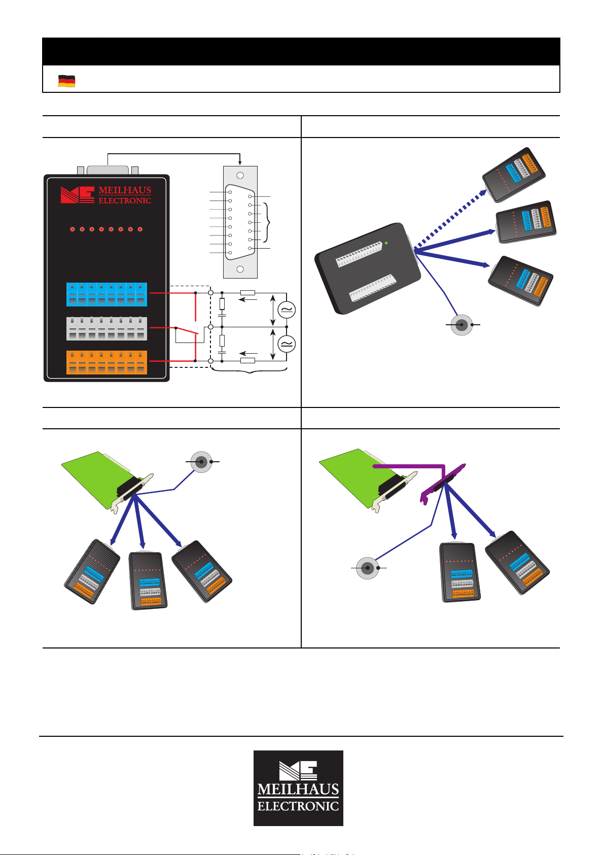
Anschlußbelegung ME-UBRE Anschluß an USB-Messboxen
PMD-1008:
3-fach Split-Kabel "ME AK-DUB"
1
9
2
10
3
11
4
12
5
13
6
14
7
15
8
VCC
GND
VCC
LabJack U12:
2-fach Split-Kabel "ME AK-DUB/LJ"
ME-UBRE
Kanal 8
Kanal 7
Kanal 6
Kanal 5
Kanal 4
Kanal 3
Kanal 2
Kanal 1
12345678
NO
COM
NC
Last
R
I
1
1
U
Last
1
U
2
I
2
C
1
R
2
C
2
Kontaktschutzschaltung*
PMD-1008
LabJack U12
Externe Spannungsversorgung (+8 VDC)
z.B. Steckernetzteil vom Typ MW17-GS/6
Abb. 2: Anschluß USB-Messboxen
Abb. 1: Anschlußbelegung/Kontaktschutzschaltung
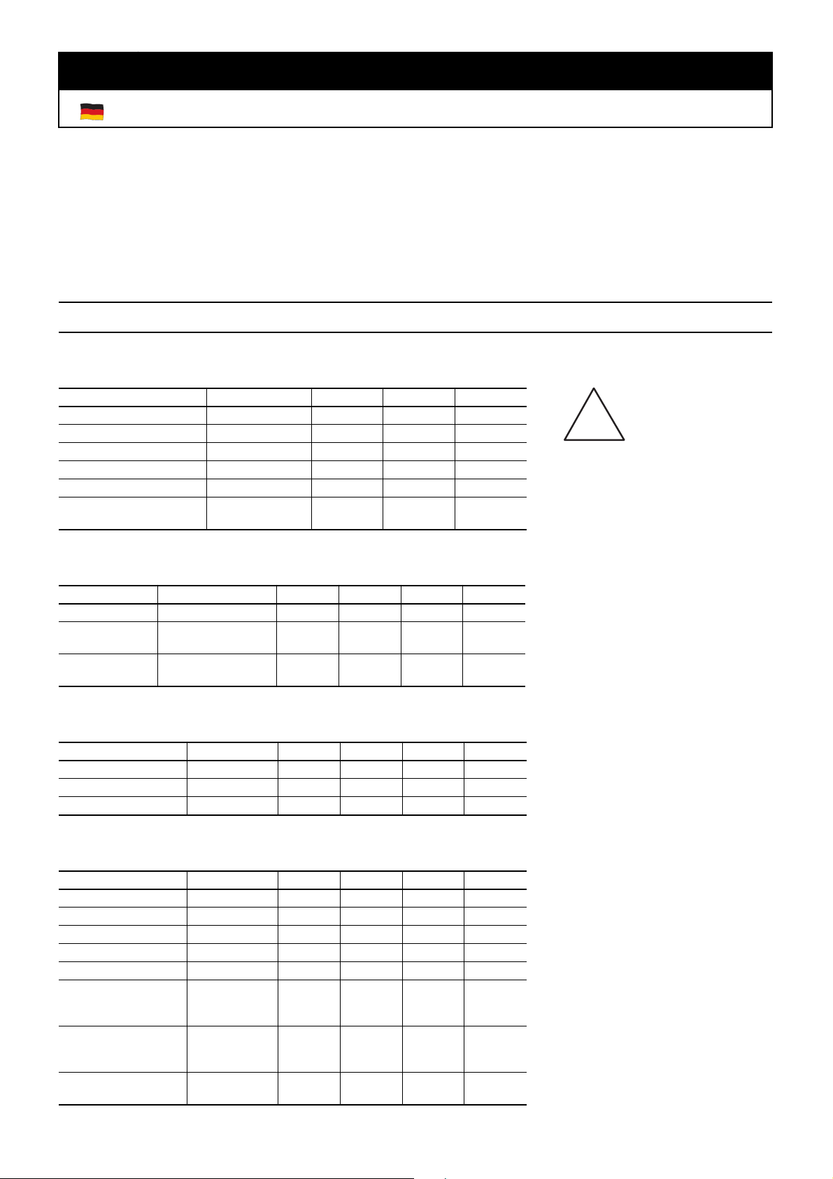
Anschluß an ME-1400/A/B Anschluß an ME-Karten mit ST2
Externe Spannungsversorgung
ME AK-D25F/S
ME-1400
GND (außen)+8VDC (innen)
3,5 mm
Klinkenbuchse
ME-46xx
ME-6x00
ME-630(USB)
ME AK-D7815/1400
3,5 mm
Klinkenbuchse
+8VDC
(innen)
GND
(außen)
Externe Spannungsversorgung
8 Bit Port A
8 Bit Port B
8 Bit Port C
8 Bit Port A/C
3,5 mm
Klinkenbuchse
GND (außen)+8VDC (innen)
ME AK-D2515/4000
8 Bit Port B/D
Abb. 3: Anschluß ME-1400/A/B Abb. 4: Anschluß ME-Karten mit ST2
*Kontaktschutzschaltung
Auf der ME-UBRE kommen elektromechanische Leistungsrelais zum Einsatz, die bis zu 5 A schalten können. Da beim
Schaltvorgang Induktionsspannungen und hohe Einschaltströme auftreten wird die Verwendung einer Kontaktschutzschaltung dringend empfohlen. Um die Wirksamkeit der Schutzschaltung zu gewährleisten sollte diese nicht mehr als
20 cm vom Kontakt entfernt angeordnet sein. Fortsetzung nächste Seite ➜
Meilhaus Electronic GmbH
Fischerstraße 2
D-82178 Puchheim
Tel.: +49 (0) 89/89 01 66-0
Fax: +49 (0) 89/80 83 16
E-Mail Support: support@meilhaus.com
Treiber-Software, Handbücher:
www.meilhaus.de/download
© Copyright 2004 Meilhaus Electronic GmbH.
Alle Rechte vorbehalten. Wir möchten darauf hinweisen,
daß die Meilhaus Electronic GmbH weder die juristische
Verantwortung oder irgendeine Haftung für Folgen, die
auf fehlerhafte Angaben zurückgehen, übernehmen kann.
Page 2
ME-UBRE
(Fortsetzung)
In Abbildung 1 sehen Sie eine typische Schaltung dieser Art. Die Werte sind abhängig von der Last und den Relaiseigenschaften. Der Kondensator C unterdrückt die Entladung bei Kontaktöffnung, der Widerstand R begrenzt den Strom,
wenn das nächste Mal geschaltet wird. Die Schaltung ist für Gleich- und Wechselspannung gleichermaßen geeignet. Da
die Relais sowohl einen Arbeits (NO)- als auch einen Ruhekontakt (NC) haben, müssen Sie die Schutzschaltung stets
für jeden Kontakt vorsehen, der eine nennenswerte Last schaltet.
Als Richtlinie für die Auswahl von R
R
: 0,5 bis 1 Ω je 1 V der Schaltspannung U
x
und C
x
gilt:
x
x
C
: 0,5 bis 1 µF je 1 A des Schaltstromes I
x
Spezifikationen
Höchstzulässige Grenzwerte
Randbedingungen: T
Meßgröße Testkriterien MIN MAX Einheit
Betriebsspannung U
Eingangsspannung U
Schaltspannung U
Schaltspannung U
Dauerstrom I
Isolationsspannung
Spule/Kontakte U
out
out
out
ISO
=25°C
A
b
in
zerstörungsfrei -0,5 +10 V
zerstörungsfrei -0,5 30 V
zerstörungsfrei 240 VAC
zerstörungsfrei 30 VDC
zerstörungsfrei 5 A
4000 V
ac,rms
Empfohlene Betriebsbedingungen
Randbedingungen: U
Meßgröße Testkriterien MIN Typ MAX Einheit
U
out
I
out
Abisolierlänge berührungsgeschützt
=7…9V, T
b
zeitlich unbegrenzt,
alle Kanäle
nach IP20
=25°C
A
12 240 V
100 5000 mA
56mm
Statische Werte
Randbedingungen: U
Meßgröße Testkriterien MIN Typ MAX Einheit
U
in,H
U
in,L
I
in,H
=7…9V, T
b
=25°C
A
3,5 5 V
1,5 V
Uin=3,85V 0,93 1,35 mA
x
!
Warnhinweis
Das Gerät ist konform nach der EG
Niederspannungsrichtlinie 73/23/
EWG entwickelt und gefertigt worden. Bitte beachten Sie bei Inbetriebnahme des Gerätes insbesondere bei
Betrieb mit Spannungen größer 42 V
die einschlägigen Normen und Installationsvorschriften sowie die
VDE-Anforderungen. Für eine fehlerhafte Installation, Inbetriebnahme
und Handhabung während des Betriebes und daraus folgende Schäden, kann seitens der Meilhaus
Electronic GmbH keine Haftung
übernommen werden.
Dynamische Werte
Randbedingungen: U
Meßgröße Testkriterien MIN Typ MAX Einheit
f
in
t
pd,on
t
pd,off
Prellzeit Schließer 1,5 ms
Prellzeit Öffner 5 ms
Kontaktlebensdauer I
Kontaktlebensdauer I
Kontaktlebensdauer I
=7…9V, T
b
=25°C
A
lastfrei 20 Hz
5ms
2,5 ms
=5A,
out
U
=250VAC,
out
cos ϕ =1
=2A,
out
U
=250VAC,
out
cos ϕ =0,4
=1A,
out
U
=24VDC
out
1 x 10
2 x 10
2 x 10
5
5
5
1 x 10
7
Page 3

ME-UBRE
Desktop Relay Box with 8 Type C Relays (5 A/240 VAC)
Pinout ME-UBRE Connection to USB DAQ boxes
PMD-1008:
Triple split cable "ME AK-DUB"
LabJack U12:
Dual split cable "ME AK-DUB/LJ"
ME-UBRE
Channel 8
Channel 7
Channel 6
Channel 5
Channel 4
Channel 3
Channel 2
Channel 1
1
9
2
10
3
11
4
12
5
13
6
14
7
15
8
VCC
GND
VCC
12345678
NO
COM
NC
Load
R
I
1
1
U
Load
1
U
2
I
2
C
1
R
2
C
2
Contact protection circuit*
PMD-1008
LabJack U12
3,5 mm
jack coupling
External power supply (+8 VDC)
e. g. power supply unit of type MW17-GS/6
Diagram 2: Connection USB DAQ boxes
Diagram 1: Pinout
Connection to ME-1400/A/B Connection to ME-Boards with ST2
ME-1400
GND (outside)+8VDC (inside)
3,5 mm
jack coupling
ME-46xx
ME-6x00
ME-630(USB)
ME AK-D25F/S
ME AK-D7815/1400
3,5 mm
jack coupling
GND (outside)+8VDC (inside)
ME AK-D2515/4000
+8VDC
(inside)
GND
(outside)
External power supply
8 bit port A
8 bit port B
8 bit port C
8 bit port A/C
8 bit port B/D
Diagram 3: Connection ME-1400/A/B Diagram 4: Connection ME-Boards with ST2
* Contact Protection circuit:
On the ME-UBRE electro-mechanical power relays are used. They can switch currents up to 5 A. During switching the
relays induced voltages and high transient currents occur. Therefore the use of a protection circuit for the contacts is
urgently needed. To guarantee the efficiency of the protection circuit the distance should not exceed more than 20 cm.
Meilhaus Electronic GmbH
Fischerstraße 2
D-82178 Puchheim
Tel.: +49 (0) 89/89 01 66-0
Fax: +49 (0) 89/80 83 16
E-Mail Support: support@meilhaus.com
Treiber-Software, Handbücher:
www.meilhaus.de/download
© Copyright 2004 Meilhaus Electronic GmbH.
Alle Rechte vorbehalten. Wir möchten darauf hinweisen,
daß die Meilhaus Electronic GmbH weder die juristische
Verantwortung oder irgendeine Haftung für Folgen, die
auf fehlerhafte Angaben zurückgehen, übernehmen kann.
Page 4

ME-UBRE
(continued)
The diagram 1 shows a typical circuitry that could be used. The values of the components used depend on the load
and the relay properties. The condensator C suppresses the discharge when contact opens and the resistor R limits the
current when switching the next time. The circuitry can be used for DC and AC operation. The ME-UBRE offers a make
contact as well as a break contact. Therefore the protection circuit must be provided for every contact switching a considerable load.
As a rule for selection of Rx and Cx use:
Rx: 0,5…1 Ω per 1 V of switching voltage U
x Cx
: 0,5…1 µF per 1 A of switching current I
Specifications
Maximum Ratings
Conditions: TA=25°C
Measurement Values Test Conditions MIN MAX Unit
Operating voltage U
Input voltage U
Switching voltage U
Switching voltage U
Permanent current I
Isolation voltage
coil/contact U
in
ISO
b
out
out
out
non destructive -0,5 +10 V
non destructive -0,5 30 V
non destructive 240 VAC
non destructive 30 VDC
non destructive 5 A
4000 V
ac,rms
Recommended Operating Conditions
Conditions: Ub=7…9V, TA=25°C
Measurement Values Test Conditions MIN Typ MAX Unit
U
out
I
out
Stripping length protected against
time unlimited, all
channels
contact (IP20)
12 240 V
100 5000 mA
56mm
x
!
Warning
The device was developed and produced in accordance to the EMC low
voltage directive 73/23/EWG. When
putting the device into operation especially with voltages greater than
42 V please follow the appropriate
standards, installation instructions
and national safty standards.
Meilhaus Electronic GmbH assumes
no responsibility for damage in case
of faulty installation, operation or
handling.
Static Values
Conditions: Ub=7…9V, TA=25°C
Measurement Values Test Conditions MIN Typ MAX Unit
U
U
I
in,H
in,L
in,H
Uin=3,85V 0,93 1,35 mA
3,5 5 V
1,5 V
Dynamic Values
Conditions: Ub=7…9V, TA=25°C
Measurement Values Test Conditions MIN Typ MAX Unit
f
in
t
pd,on
t
pd,off
bounce time make contact 1,5 ms
bounce time break contact 5 ms
Contact life time I
Contact life time I
Contact life time I
without load 20 Hz
5ms
2,5 ms
=5A,
out
U
=250VAC,
out
cosϕ=1
=2A,
out
U
=250VAC,
out
cosϕ=0,4
=1A,
out
U
=24VDC
out
1 x 10
2 x 10
2 x 10
5
5
5
1 x 10
7
 Loading...