

Page 1
Meilhaus Electronic GmbH
Am Sonnenlicht 2
82239 Alling/Germany
E-Mail sales@meilhaus.com
Web www.meilhaus.com
% +49 - (0)81 41 - 52 71-0
FAX +49 - (0)81 41 - 52 71-129
All trademarks acknowledged.
Information contained in this
document is subject to change
without notice.
2 Channel USB Scope
„MEphisto Scope“
(UM202, UM203)
with MEphistoLab2 Software
Quick Start Guide
Note also the „Quick Start Video“ and the help le,
installed with the MEphistoLab2 software.
Revision: 2.0
Warnings
The “MEphisto Scope” has a maximum input voltage of ±10 VDC. Measuring higher voltages than this
directly may damage the instrument and invalidate the warranty.
The “MEphisto Scope” is not electrically isolated, i. e. in „online“ operation the ground of
the device connects directly to the ground of
the PC via the USB cable. If you are using a
standard desktop PC the ground of the device connects to earth by the power cable
(with protective earth conductor). How ever,
this reference to earth po tential is missing in
case of connection with a laptop or in offl ine
operation. Therefore a good earthing via the
earth connection at the rear of the housing
and special caution are strictly necessary
for your own safety!
Measuring voltages great er than 42 V, especially mains voltage may only be done by quali ed specialists.
Use a high voltage differential probe for this. Not e, that there is an electrical connection between the
shield of the BNC connectors and the housing. In „online“ operation it is routed along via the USB cable to the
PC chassis. That is by an accidentially connection e. g. of the live contact of a schuko socket with ground of
your probe, then mains voltage (110 V/230 V) is attached to the housing of the MEphisto Scope. This means
danger of life! Please follow the appropriate standards, ins tallation instructions and national safty standards.
Meilhaus Electronic GmbH assumes no responsibility for damage in case of faulty installation, operation or
handling.
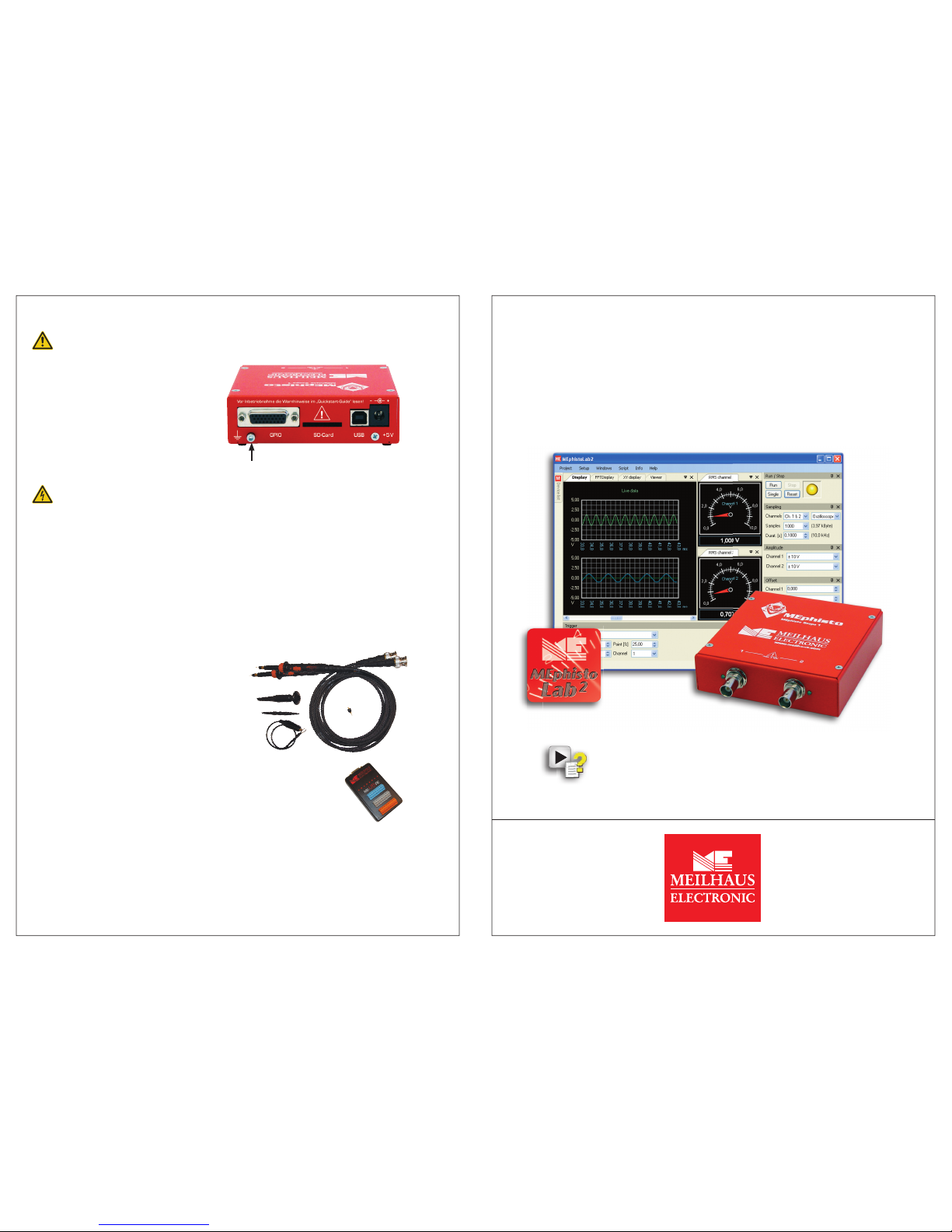
What‘s in the Box?
Please make sure, that your “MEphisto Scope” box includes the following items:
• 1 x USB scope “MEphisto Scope” (UM202, UM203) hardware.
• ME-Power-DVD with driver and DAQ software “MEphistoLab2”.
• USB cable (type A - type B)
• This Getting Started Guide.
Accessories (optional)
“ME-Probe LF Pair”
2 passive modular probes (1:1/1:10 selectable) with accessories. Bandwidth: 15/150
MHz, 47/15.5 pF, 1/10 MΩ, 600 Vp CAT I.
“ME-UB” series
Connect up to 3 “ME-UB” boxes to the 26pin D-sub with a triple
break-out cable “ME AK-DUB/UM202”.
Available models: terminal block, opto-isolated inputs, opto-isolated outputs, relays
Support
Should you experience problems with the device or software, please send an E-Mail
to support@meilhaus.com.
Newest info and software updates on our web sit e:
http://www.meilhaus.org/downloadserver/mephistoscope.htm
2 x
2 x
Earth connection
4 1
Page 2
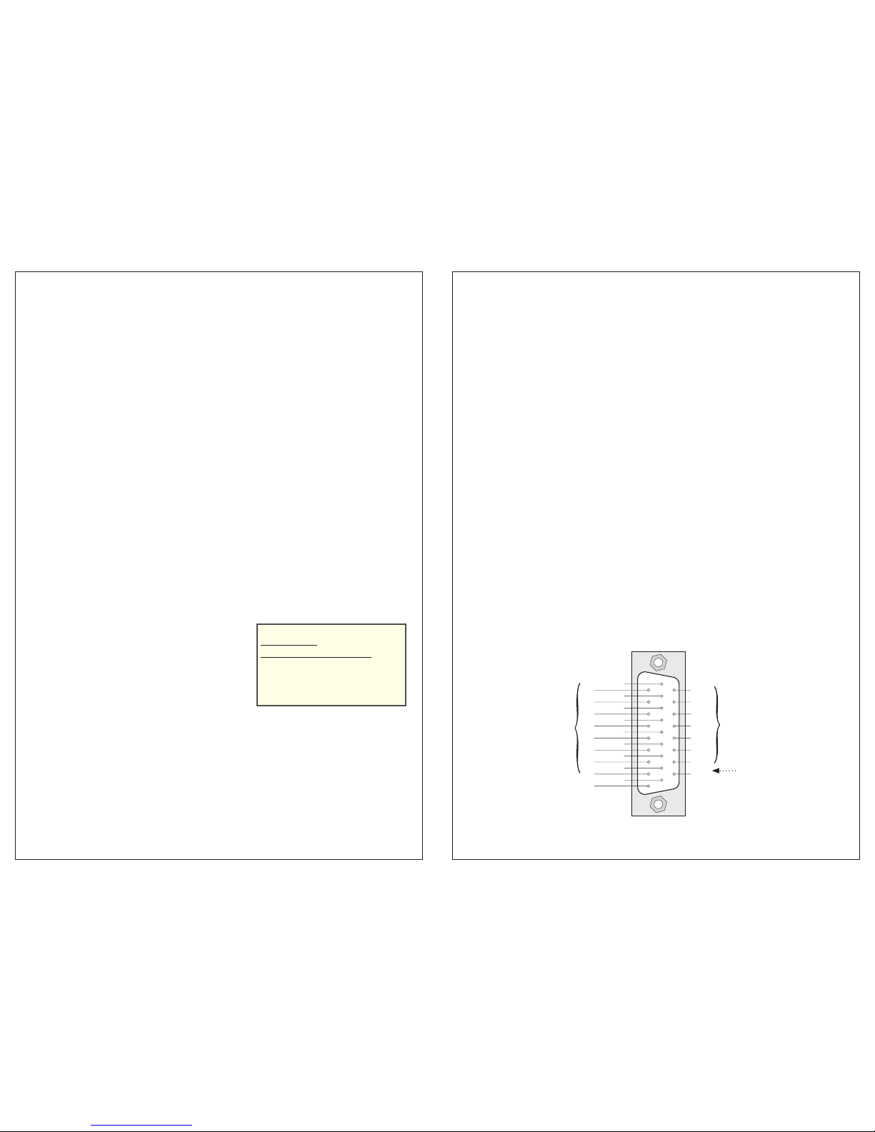
MEphisto Scope and MEphistoLab2 – Short Description
“MEphisto Scope” is a mobile multi-functional device in a compact metal box. The module is
powered from the PC via the USB inter face; no external power supply is necessary. Both
analog inputs have BNC connectors for standard oscilloscope probes. Each channel has it’s
individual 16 bit A/D converter which gives you simultaneous sampling rates of 1 MS/s on
both channels. The input voltage range is ±10 V. Depending on the operation mode multiple
trigger modes are available.
The 2nd generation of the MEphistoLab software was developed completely new and
provides a virtual instrument panel, which gives you easy and quick access to all functions of
the device. The following operation modes are provided
(if you don´t have a MEphisto Scope available
you can choose the option „Simulation“ via the menu „Setup – Options – Driver“):
• „Oscilloscope“ 2 channels, 1 MS/s max. per channel, voltage range ±10 V
• „Logic Analyser“ 16 channels (D0…15), 100 kS
/
s max. per channel, 5 V CMOS level
• „Analog Data Logger“ 2 analog channels, 100 kS
/
s max., voltage range ±10 V
• „Digital Data Logger“ 16 channels (D0…15), 100 kS
/
s max., 5 V CMOS level
• „Analog Meter“ 2 channels (AC
RMS
/AC/DC) with up to 6 virtual analog meters
• „Digital I/O“ 24 digital I/Os, each bit congured indi vidually, 5 V CMOS level
• „Data Viewer“ for analysing data alr eady stored
• „Ofine Mode“ the model UM203 can store data on a SD card without a PC
• „Script Editor“ Write your own code in C#, e. g. for automatic measurements
On demand you can change the program language (English/German) in the menu „Setup – Options – Language“
( program restart required). You nd a detailed description of the MEphistoLab
2
software in the help le.
Hardware Specifications (UM202, UM203)
Analog Inputs
Number, resolution 2 x 16 bit
Total sampling rate 2 MS/s (2 channels)
Simultaneous channels 2
Input voltage range ±100 mV … ±10 V
Analog bandwidt h (-3 dB) 500 kHz
Sample memory 256 kS
Trigger types Level, window, edge,
slope (dU/dt), external, manual
Digital Inputs/Outputs
Number 24 I/Os
Conguration each bit programmable as input or output (outputs can be read back)
Output current (25 °C) sink: 10 mA, source: 5 mA
Signal level +5 V (CMOS)
General Data
PC interface USB 2.0 full-speed (USB 1.1 compatible)
Power supply +5 V/0.85 W via USB interface
Reference ground PC ground (PC_GND)
Connectors Analog channels: 2 x BNC connectors (front panel)
Digital channels: 26-pin D-sub female (rear panel),
USB connector: Type B (rear panel)
Size (W x H x D) 110 mm x 35 mm x 136 mm (incl. connectors)
Operating temperature 0…70 °C
Installation
System requirements for MEphistoLab2: Windows 7, Vista, XP (SP2), 2000 (SP4);
Microsoft
®
.NET Framework version 2.0 or higher, USB driver (32/64bit)
1. Connect the “MEphisto Scope” to a USB port of your PC using the USB cable included
with the device. ⇒ The hardware wizard will automatically detect the new USB device
and will display the message “New hardware found”. The follow ing description is to be
orientated towards Windows XP but applies analogously to other Windows versions.
However the dialogs may differ depending on your Windows ver sion.
2. Insert the CD/DVD included with the package into the drive of your PC or make the
USB driver available by download
http://www.meilhaus.org/downloadserver/mephistoscope.htm
3. In the hardware wizard select the option “Search for a suitable driver for my device
(recommended)” and click “Next”. If Windows displays a message, telling you the driver
is not Microsoft certied, just skip this window.
⇒ The system driver will be installed and the entry “MEphisto Scope” will be added in
the device manager under the device class “Meilhaus DAQ Boards”.
4. End the installation of the system driver by „Finish“ and continue with the installation of
the “MEphistoLab” software as follows:
5. Navigate to the setup pr ogram of the MEphistoLab
2
software on CD/DVD or to the
directory you unpacked the driver to af ter download. The default path on ME-Power-DVD
is [Drive]:\Software\MEphisto-Scope\MEphistoLab2. Start the ins tallation by doubleclicking the le “MEphistoLab2.msi”.
⇒ After the installation has nished you will nd the MEphistoLab
2
as well as the help
le, further documentation and a „Quick Star t Video“ in your Windows “Start” menu
under “Programs - Meilhaus Electronic - MEphistoLab2”.
The 26-pin D-sub female connector:
External Trigger Input
„Logic Analyser“ &
„Data Logger Digital“:
D0…15 are used to be input
channels in that operation
mode. On demand a „Pattern“
(rising/falling edge, high/low
level) can be denied as the
trigger event.
Attention!
D16…22 are reserved in
the operation modes „Logic
Analyser“ and „Data Logger
Digital“ and may not be
connected!
„Digital I/O“:
D0…23 can be congured as
input or output individually.
10
11
12
13
14
15
16
17
18
19
20
21
22
23
24
25
26
D16
D17
D18
D19
D20
D21
D22
D23
(EXT_TRIG)
D8
D9
D10
D11
D12
D13
D14
D15
PC_GND
1
2
3
4
5
6
7
8
9
D0
D1
D2
D3
D4
D5
D6
D7
PC_GND
10
11
12
13
14
15
16
17
18
19
20
21
22
23
24
25
26
D16
D17
D18
D19
D20
D21
D22
D23
(EXT_TRIG)
D8
D9
D10
D11
D12
D13
D14
D15
PC_GND
1
2
3
4
5
6
7
8
9
D0
D1
D2
D3
D4
D5
D6
D7
PC_GND
… optional for the operation modes:
• „Oscilloscope“
• „Logic Analyser“,
• „Data Logger Digital“
• „Data Logger Analog“
Stand-alone Data-logger (UM203):
„Online“ operation: via USB cable like UM202
„Ofine“ or „Stand-alone“ operation:
without connection to the PC. Logging will
be started by insertion of t he SD card into
the slot. For reading the data on the SD card
a standard SD card reader is required.
2 3
 Loading...