

Meilhaus Electronic ME-94 PCI, ME-95 PCI, ME-94 cPCI, ME-95 cPCI, ME-96 PCI User Manual
...Page 1

Meilhaus Electronic Manual
ME-94, ME-95, ME-96 6.0E
(PCI- and CompactPCI-Versions)
Opto-Isolated Digital-I/O Boards
Page 2

Imprint
Manual ME-94, ME-95, ME96
Revision 6.0
Revised: 2018-06-07
Meilhaus Electronic GmbH
Am Sonnenlicht 2
D-82239 Alling bei München
Germany
www.meilhaus.de
© Copyright 2018 Meilhaus Electronic GmbH
All rights reserved. No part of this publication may be reproduced
or distributed in any form whether photocopied, printed, put on
microfilm or be stored in any electronic media without the
expressed written consent of Meilhaus Electronic GmbH.
Important note:
The information contained in this manual has been reviewed with
great care and is believed to be complete and accurate. Meilhaus
Electronic assumes no responsibility for its use, any infringements
of patents or other rights of third parties which may result from
use of this manual or the product. Meilhaus Electronic assumes no
responsibility for any problems or damage which may result from
errors or omissions. Specifications and instructions are subject to
change without notice.
Note the Meilhaus Electronic general terms of business:
www.meilhaus.de/en/infos/my-shop/tob/
All trademarks acknowledged. All trademarks are property of their
respective owners.
Page 3
Content
1 Introduction ........................................................... 4
1.1 Important Notes ............................................................... 4
1.1.1 Use in Accordance with the Requirements ....................... 4
1.1.2 Improper Application ...................................................... 5
1.1.3 Unforeseeable Misapplications ........................................ 5
1.2 Package Contents ............................................................. 6
1.3 Features .......................................................................... 6
1.4 System Requirements ....................................................... 7
1.5 Software Support ............................................................. 7
2 Starting up ............................................................ 8
2.1 Software Installation ......................................................... 8
2.2 Test Program .................................................................... 8
3 Hardware .............................................................. 9
3.1 Block Diagrams ................................................................. 9
3.2 Digital I/O ....................................................................... 10
3.2.1 External Power Supply.................................................. 10
3.2.2 Opto-Isolated Inputs .................................................... 10
3.2.3 Opto-Isolated Outputs ................................................. 11
4 Programming ....................................................... 12
5 Appendix ............................................................. 14
A Specification .......................................................................... 14
B Pinout ................................................................................... 16
B1 ME-94........................................................................... 16
B2 ME-95........................................................................... 17
B3 ME-96........................................................................... 18
B4 External Power Connector ............................................... 19
C Accessories ........................................................................... 20
D Technical Questions ................................................................ 21
D1 Hotline ........................................................................... 21
E Index ..................................................................................... 22
Page 4
1 Introduction
Valued customer,
Thank you for purchasing this device from Meilhaus Electronic. You
have chosen an innovative high technology product that left our
premises in a fully functional and new condition.
Please take the time to carefully examine the contents of the
package for any loss or damage that may have occurred during
shipping. If there are any items missing or if an item is damaged,
please contact us immediately.
Before installing the board in your computer, we recommend you
read this manual carefully, especially the chapter describing board
installation.
The descriptions in this manual concern PCI- and CompactPCIversions of the ME-94, ME-95, ME-96 series, if not otherwise
noted.
1.1 Important Notes
1.1.1 Use in Accordance with the Requirements
The PC-boards of the ME-series are designed for acquisition and
output of analog and digital signals with a PC. Depending on type
install the models of the ME-series into:
a free PCI-slot (PCIe versions) or
a free CompactPCI-slot (3 HE cPCI versions).
For information on how to install a plug-in board or connect a USB
device, please read the manual of your PC.
Please note the instructions and specifications as presented in
this manual (Appendix A, Specifications):
Please ensure sufficient heat dissipation for the board within
the PC housing.
All unused inputs should be connected to the ground reference
of the appropriate functional section. This avoids cross talk
between the input lines.
The opto-isolated inputs and outputs achieve an electrical
isolation of the application relative to PC ground.
Page 5

Note that the computer must be powered up prior to
connecting signals by the external wiring of the board.
As a basic principle, all connections to the board should only be
made or removed in a powered-down state of all components.
Ensure that no static discharge occurs while handling the
board or while connecting/disconnecting the external cable.
Ensure that the connection cable is properly connected. It
must be seated firmly on the D-Sub connector and must be
tightened with both screws, otherwise proper operation of the
board cannot be guaranteed.
1.1.2 Improper Application
PC plug-in boards for the PCI- or CompactPCI-bus may not be taken
into operation outside of the PC. Never connect the devices with
voltage-carrying parts, especially not with mains voltage.
Make sure that no contact with voltage-carrying parts can happen
by the external wiring of the device. As a basic principle, all
connections should only be made or removed in a powered-down
state.
1.1.3 Unforeseeable Misapplications
The device is not suitable to be used as a children’s toy, in the
household or under unfavourable environmental conditions (e.g. in
the open). Appropriate precautions to avoid any unforeseeable
misapplication must be taken by the user.
Page 6
1.2 Package Contents
We take great care to ensure your delivery is complete.
Nonetheless, please check the list enclosed to verify the contents
of your delivery. You should find included:
Opto-isolated digital-I/O board (depending on the package of the
PCI or cPCI board of ME-94, ME-95 or ME-96)
Manual in PDF format on CD-ROM
Driver software on CD-ROM
For the PCI versions only: DIN-connector sourcing the
optocoupler’s power
ME-94 and ME-95: one DB25 female connector
ME-96: two DB15 female connectors
1.3 Features
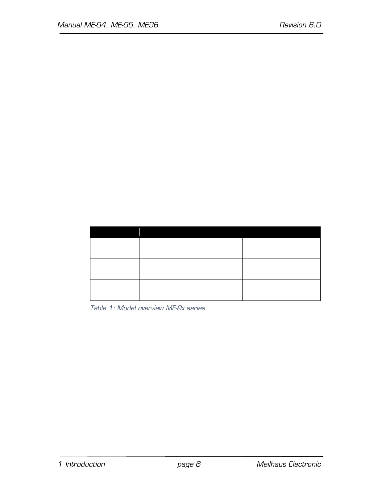
Model Overview
Model
IRQ
Inputs
Outputs
ME-94 PCI
ME-94 cPCI
*
16 opto-isolated** (24 V)
ME-95 PCI
ME-95 cPCI
*
-
16 opto-isolated (24 V)
ME-96 PCI
ME-96 cPCI
*
8 opto-isolated** (24 V)
8 opto-isolated (24 V)
* The interrupt function is not supported by the ME-iDS.
** Input port PC is not supported by ME-iDS.
The ME-9x board family includes opto-isolated digital-I/O boards for
the PCI- and cPCI-bus. The same boards on different buses are
functionally equivalent, pin-compatible, and software-compatible.
The electrical isolation on the boards prevents interference and
high voltages (e.g. voltage peaks on the ground lines) from reaching
the PC electronics. The inputs have been designed for a voltage of
typical 24 V used in control engineering.
Using the ME-iDS you can program the ME-9x series for simple input/output operations.
Page 7
ME-94: 2 x 8-bit input ports.
ME-95: 2 x 8-bit output ports.
ME-96: 1 x 8-bit input ports, 1 x 8-bit output port.
1.4 System Requirements
The ME-series may be installed into any PC (Intel® Pentium®
processor) with a free standard PCI- and CompactPCI-slot (32 bit,
33 MHz, 5 V). The board is supported by the Meilhaus Electronic
Intelligent Driver System (ME-iDS).
1.5 Software Support
The ME-series is supported by the Meilhaus Electronic Intelligent
Driver System (ME-iDS). The ME-iDS is a unique driver system
covering different devices and operating systems. It supports
Windows XP/Vista and Windows 7, 8.1, 10 and contains a universal
function library (API) for all common programming languages.
A detailed description of the functions can be found in the ME-iDS
manual on the CD/DVD enclosed.
Please also note the corresponding README-files.
Page 8

2 Starting up
Please read your computer’s instruction manual on how to install
new hardware components before installing the board.
2.1 Software Installation
Installation under Windows
The following basic procedure should be used:
If you have received the driver software as an archive file, please
unpack the software before installing the board. First choose a
directory on your computer (e.g. C:\Temp\Meilhaus\ME-iDS).
Use the Meilhaus Electronic Intelligent Driver System (ME-iDS) for
programming your new data acquisition hardware. For installation
and operation of the driver system, please follow the
documentation in electronic form included with the software
package.
2.2 Test Program
For simple testing of the board use the corresponding test
program provided with the ME-iDS.
Page 9

3 Hardware
3.1 Block Diagrams
Page 10

3.2 Digital I/O
The inputs and outputs of the ME-9x series are electrically isolated
by optocouplers. There is no electrical connection between the
hardware connected to the board and the PC.
The inputs and outputs are designed for 24 V level used in control
engineering.
For programming please read chapter 4.0 "Digital-I/O Section" on
page 12. For pin out diagrams of the connectors, see page 16.
3.2.1 External Power Supply
In order to run the ME-9x boards properly, an external power
supply is required for the optocouplers. The power supply must be
connected to the D-Sub connector of the boards (pins „ext. GND“
and „ext. V+“, see chapter "B Pinout" on page 16 ff). Alternatively,
the external power can be supplied via a low-voltage connector (DIN
45323) on the standard PCI versions. The power supply is
connected to the „V+“ pins at the D-Sub connector(s) on the
board.
The external supply voltage can be within 20 V and 28 V, so that
small alterations in the voltage will have no effect on the board’s
function.
3.2.2 Opto-Isolated Inputs
The opto-isolated inputs of the ME-94 and ME-96 are connected
to the optocouplers through resistors Rv. These resistors are sized
for an input high level of typical 24 V. For over-voltage protection of
the optocouplers a protection diode is provided. The digital lines
must be referenced to the external ground (ext. GND).
Page 11

3.2.3 Opto-Isolated Outputs
The opto-isolated output channels of the ME-95 and ME-96 provide
special output drivers. After power-up, the outputs are set to a
defined, high-impedance state. A reference to external ground (ext.
GND) must be done. The output current may not exceed I
Out
=
100 mA per channel.
On all ME-96 versions the input port is always the lower one and
the output the upper one.
Page 12

4 Programming
For programming the device please use the Meilhaus Electronic
Intelligent Driver System (ME-iDS) included in your package. The
ME-iDS is a unique driver system covering different devices and
operating systems. It supports Windows XP and higher and
contains a universal function library (API) for all common
programming languages (the extent of the current software
support can be found in the README-files of the ME-iDS).
A detailed description of the functions can be found in the ME-iDS
manual (see CD/DVD enclosed or online:
www.meilhaus.de/download/ME-iDS.
Further details regarding the assignment of the subdevices and
device specific arguments can be found in the help file (help file
format under Windows, *.chm) which can be accessed via the „ME-
iDS Control Center“ in the info area of the task bar (as a rule in
the lower right corner of the screen) or via the Windows start
menu.
Digital-I/O Section
The ME-94 and ME-96 use an 8255 compatible PIO-device. Both
boards can be exclusively programmed in the operation mode
„without interrupt“ (mode 0) of this component. The digital-I/O
ports on the ME-95 are designed with a simple data buffer (latch).
Each digital port of the ME-9x boards is considered to be an
independent functional group (subdevice) in the Meilhaus Intelligent
Driver System (ME-iDS). The following table shows the assignment
of subdevices:
Port
Port width
ME-94
ME-95
ME-96
PA0…7
8 bit
subdevice 0
(ME_TYPE_DI)
subdevice 0
(ME_TYPE_DO)
subdevice 0
(ME_TYPE_DI)
PB0…7
8 bit
subdevice 1
(ME_TYPE_DI)
subdevice 1
(ME_TYPE_DO)
subdevice 1
(ME_TYPE_DO)
For switching the digital ports please read chapter 3.2 on page
10.
Page 13

Simple Input/Output
The input/output of single digital values is done in operation mode
„Single“. Each digital port is accessed as a unique subdevice of
type ME_TYPE_D resp. ME_TYPE_DO, subtype ME_SUBTYPE_SINGLE. Note the order of operation as described in the MEiDS manual. The following parameters can be configured by the
functions and :
Subdevice: see Table 2: Assignment port to subdevice.
Port direction: fixed by the hardware.
Port width: bit or byte operation.
Page 14

5 Appendix
A Specification
PCI Interface
Bus system
Standard PCI (32 bit, 33 MHz, 5 V)
(depending on model)
CompactPCI (32 bit, 33 MHz, 5 V)
Plug&Play
automatic assignment of resources
Digital opto-isolated Inputs (ME-94 and ME-96)
Number
ME-94: 16;
ME-96: 8
PIO device
8255-compatible
Input voltage
low: 0…12 V (PCI, cPCI)
high: 13...24 V (PCI, cPCI)
Input current
at 24 V input voltage
PCI, cPCI: 10 mA
Electrical isolation
500 V DC (referenced to PC-GND)
Transfer rate
Max. 1 kHz
Digital opto-isolated Outputs (ME-95 and ME-96)
Number
ME-95:16;
ME-96: 8
PIO Device
ME-95: discrete components
ME-96: 8255-compatible
Power-up
Output transistors disabled, output pins are
tristate after power-up.
Ext. power supply
24 V nominal
Output current
max. 100 mA per line
Electrical isolation
500 V DC
Transfer rate
max. 1 kHz symmetrically
Page 15

General Information
Power consumption at
+5 V
ME-94 PCI/cPCI: typ. 250 mA
ME-95 PCI/cPCI: typ. 400 mA
ME-96 PCI/cPCI: typ. 380 mA
Fuse for external
power
F1: 1,6 AT/250 V (only ME-95, ME-96)
Physical size (mm)
100 x 160 (cPCI models)
174 x 98 (PCI models)
Connectors
25-pin D-Sub male connector ME-94 and
ME-95);
2 x 15-pin D-Sub connector (ME-96);
2-pin low-voltage female connector DIN 45323
(not for cPCI, supply over cPCI slot connector
there)
Operating
temperature
0…70 ºC
Storage temperature
-40…100 ºC
Relative humidity
20…55 % (non-condensing)
Certification
CE
Page 16

B Pinout
B1 ME-94
*Pin not supported by ME-iDS
Page 17

B2 ME-95
Page 18

B3 ME-96
Output Port of the ME-96 (top)
Input Port of the ME-96 (bottom)
*Pin not supported by ME-iDS.
Page 19

B4 External Power Connector
…for the optocouplers (only standard PCI models)
Page 20

C Accessories
We recommend to use high-quality connector cables with singleshielded lines per channel.
For further accessories please refer to the current Meilhaus
Electronic catalog and the internet:
www.meilhaus.de/en/pc-boards/accessories/
Page 21

D Technical Questions
D1 Hotline
Should you have questions or inquiries concerning your Meilhaus
device, please contact us:
Meilhaus Electronic GmbH
Repair & Service
Am Sonnenlicht 2
D-82239 Alling
Sales: Support:
Tel.: (08141) 52 71 – 0 Tel.: (08141) 52 71 – 188
Fax: (08141) 52 71 – 129 Fax: (08141) 52 71 – 169
eMail: sales@meilhaus.de eMail: support@meilhaus.de
Download-Server and Driver Update:
To download current driver versions for Meilhaus Electronic devices
as well as manuals in PDF format, please go to:
www.meilhaus.org/driver
Service Department with RMA Process:
In case you need to return a board for repair purposes, we strongly
ask you attach a detailed description of the error as well as
information regarding your computer/system and the software
used. Please register online using our RMA process:
www.meilhaus.de/en/infos/service/rma.htm.
Page 22

E Index
A
Accessories 20
Appendix 14
B
Block Diagrams 9
D
Digital I/O 10
Digital-I/O Section 12
E
External Power Connector 19
External Power Supply 10
F
Features 6
H
Hardware 9
Hotline 21
I
Important Notes 4
Improper Application 5
M
ME-94 16
ME-95 17
ME-96 18
O
Opto-Isolated Inputs 10
Opto-Isolated Outputs 11
P
Package Contents 6
Pinout 16
Programming 12
S
Simple Input/Output 13
Software Installation 8
Software Support 7
Specifications 14
Starting up 8
System Requirements 7
T
Technical Questions 21
Test Program 8
 Loading...