

Meilhaus Electronic ME-90, ME-9000, ME-9100, ME-9300 Electronic Manual
Meilhaus Electronic Manual
ME-90/9000/9100/9300 Series 3.0E
(PCI-, PCI-Express-, PC/104-Plus- and
CompactPCI-Versions)
RS-232 or RS-422/485 Interface Boards with up
to 16 Ports (optional: Opto-Isolation)

Imprint
Manual ME-9000 Series
Revision 3.0E
Revised: 2018-05-09
Meilhaus Electronic GmbH
Am Sonnenlicht 2
D-82239 Alling bei München
Germany
www.meilhaus.de
© Copyright 2018 Meilhaus Electronic GmbH
All rights reserved. No part of this publication may be reproduced
or distributed in any form whether photocopied, printed, put on
microfilm or be stored in any electronic media without the
expressed written consent of Meilhaus Electronic GmbH.
Important note:
The information contained in this manual has been reviewed with
great care and is believed to be complete and accurate. Meilhaus
Electronic assumes no responsibility for its use, any infringements
of patents or other rights of third parties which may result from
use of this manual or the product. Meilhaus Electronic assumes no
responsibility for any problems or damage which may result from
errors or omissions. Specifications and instructions are subject to
change without notice.
Note the Meilhaus Electronic general terms of business:
www.meilhaus.de/en/infos/my-shop/tob/
All trademarks acknowledged. All trademarks are property of their
respective owners.
Content
1 Introduction ........................................................... 7
1.1 Important Notes ...................................................................... 7
1.1.1 Use in Accordance with the Requirements ............................. 7
1.1.2 Improper Application ............................................................ 8
1.1.3 Unforeseeable Misapplications .............................................. 8
1.2 Package Contents .................................................................... 9
1.3 Features ................................................................................. 9
1.4 System Requirements ............................................................ 12
1.5 Available Software .................................................................. 12
2 Installation .......................................................... 14
2.1 Hardware Installation.............................................................. 14
2.2 Driver Installation ................................................................... 15
2.2.1 Unpacking the Driver Software ........................................... 15
2.2.2 Installation under Windows* 95/98/Me/2000/XP ................... 15
2.2.3 Checking Installation under Windows ................................... 16
2.2.4 Installation under Windows NT 4.0 ...................................... 18
2.2.5 Checking the Installation under Windows NT 4.0 ................... 18
2.2.6 Installation of the ME Software Developer Kit ...................... 18
2.2.7 Updating the System Driver ............................................... 19
2.2.7.1 …under Windows 95/98/Me/2000/XP ............................. 19
2.2.7.2 …under Windows NT 4.0 ............................................... 19
2.3 Port Configuration .................................................................. 20
2.3.1 …under Windows 95/98/Me ................................................ 20
2.3.1.1 Port Settings .............................................................. 21
2.3.1.2 Settings „Advanced“ .................................................... 22
2.3.2 …under Windows 2000/XP ................................................. 22
2.3.2.1 Port Settings .............................................................. 23
2.3.2.2 Settings “Advanced” .................................................... 24
2.3.3 …under Windows NT 4.0 .................................................... 25
2.3.3.1 Settings “ME SIO Ports” .............................................. 27
2.3.3.2 Port Settings .............................................................. 27

3 Hardware ............................................................ 29
3.1 Block Diagram ME-9000 ......................................................... 29
3.2 Block Diagram ME-9100 ......................................................... 30
3.3 Block Diagram ME-9300 ......................................................... 31
3.4 Block Diagram ME-90 PC/104-Plus .......................................... 32
3.5 Hardware Options .................................................................. 33
3.5.1 ME-9000 PCI/PCIe/cPCI ...................................................... 33
3.5.1.1 Multi-I/O Port............................................................... 33
3.5.1.2 Echo ON/OFF ............................................................... 33
3.5.2 ME-9100 PCI .................................................................... 39
3.5.3 ME-9100 CompactPCI ....................................................... 40
3.5.4 ME-9300 PCI .................................................................... 41
3.5.5 ME-90 PC/104-Plus ........................................................... 42
3.5.5.1 Multi-I/O Port............................................................... 42
3.5.5.2 Assignment of the PCI Slots ......................................... 43
3.5.5.3 Configuration of RS-422/485 Ports ............................... 43
3.5.5.4 Echo ON/OFF ............................................................... 45
3.6 Connection Options ................................................................ 46
3.6.1 Dual/Quad/Octopus Cables .................................................. 46
3.6.2 Flat Ribbon Cable to 9-pin D-Sub Connectors ....................... 46
3.6.3 Terminal Panel for ME-9000/9100 ...................................... 47
3.6.4 Terminal Panel for ME-9300 ............................................... 49
3.7 Operation Modes .................................................................... 52
3.7.1 The RS-232 Standard ........................................................ 52
3.7.2 The RS-422/485 Standard ................................................. 53
3.7.2.1 RS-422 ....................................................................... 54
3.7.2.1.1 ME-9000 ................................................................ 55
3.7.2.1.2 ME-9100 ................................................................ 55
3.7.2.1.3 ME-90 PC/104-Plus ................................................. 56
3.7.2.2 RS-485 Half-Duplex ...................................................... 56
3.7.2.2.1 ME-9000 ................................................................ 57
3.7.2.2.2 ME-9100 ................................................................ 57
3.7.2.2.3 ME-90 PC/104-Plus ................................................. 58

3.7.2.3 RS-485 Full-duplex ....................................................... 58
3.7.2.3.1 ME-9000 ................................................................ 59
3.7.2.3.2 ME-9100 ................................................................ 59
3.7.2.3.3 ME-90 PC/104-Plus ................................................. 60
4 Programming ....................................................... 61
4.1 ME-9000 Multi-I/O Driver ........................................................ 61
4.1.1 Visual C++ ....................................................................... 61
4.1.2 Visual Basic ...................................................................... 62
4.1.3 Delphi ............................................................................... 62
4.1.4 Agilent VEE ....................................................................... 63
4.1.5 LabVIEW ........................................................................... 63
4.2 Digital-I/O Section .................................................................. 63
4.3 Counter ................................................................................. 66
5 Function Reference .............................................. 69
5.1 General Notes ........................................................................ 69
5.2 Naming Conventions ............................................................... 69
5.3 Description of the API Functions .............................................. 70
5.3.1 Error Handling ................................................................... 72
5.3.2 General Functions ............................................................. 76
5.3.3 Digital Input/Output ........................................................... 80
5.3.4 Counter Functions ............................................................. 91
Appendix ................................................................. 100
A Specification ........................................................................ 100
B Pinout ................................................................................. 104
B1 ME-9000/9100 RS-232 ....................................................... 104
B2 ME-9000/9100 RS-422/485 ................................................. 105
B3 ME-9300 RS-232 ................................................................ 106
B4 ME-90PC/104-Plus ............................................................... 107
B5 Auxiliary Connector ST2 (ME-9000) ....................................... 109
B6 Auxiliary Connector ST3 (ME-90 PC/104-Plus) ........................ 110
B7 9-pin Male Connector ME-9000/9100/9300 ........................... 111
B8 9-pin Male Connector ME-90 PC/104-Plus .............................. 112
B9 8-pin RJ-45 Female Connectors ............................................ 112

B10 Null Modem Cable ................................................................. 113
C Accessories ......................................................................... 114
D Technical Questions .............................................................. 116
D1 Hotline ................................................................................ 116
E Constant Definitions ........................................... 117
F Index ................................................................................... 119

1 Introduction
Valued customer,
Thank you for purchasing this device from Meilhaus Electronic. You
have chosen an innovative high-technology product that left our
premises in a fully functional and new condition.
Please take the time to carefully examine the contents of the
package for any loss or damage that may have occurred during
shipping. If there are any items missing or if an item is damaged,
please contact us immediately.
Before installing the board in your computer, we recommend you
read this manual carefully, especially the chapter describing board
installation.
The descriptions in this manual concern PCI-, PCI-Express- and
CompactPCI-versions of the ME-9000 series, if not otherwise
noted.
1.1 Important Notes
1.1.1 Use in Accordance with the Requirements
The PC boards of the ME-series are designed for acquisition and
output of analog and digital signals with a PC. Depending on type
install the models of the ME-series into:
a free PCI slot or
a free PCI Express slot or
a free CompactPCI slot.
The boards of the ME-90 PC/104-Plus series are serial interface
boards (RS-232 or RS-422/485) in the PC/104 format to be
integrated in a PC/104-Plus stack.
For information on how to install a plug-in board or connect a USB
device, please read the manual of your PC.
Please note the instructions and specifications as presented in
this manual (Appendix A, Specifications):
Please ensure sufficient heat dissipation for the board within
the PC housing.

All unused inputs should be connected to the ground reference
of the appropriate functional section. This avoids cross talk
between the input lines.
The opto-isolated inputs and outputs achieve an electrical
isolation of the application relative to PC ground.
Note that the computer must be powered up prior to
connecting signals by the external wiring of the board.
As a basic principle, all connections to the board should only be
made or removed in a powered-down state of all components.
Ensure that no static discharge occurs while handling the
board or while connecting/disconnecting the external cable.
Ensure that the connection cable is properly connected. It
must be seated firmly on the D-Sub connector and must be
tightened with both screws, otherwise proper operation of the
board cannot be guaranteed.
1.1.2 Improper Application
PC plug-in boards for the PCI-, PCI-Express- or CompactPCI-bus
may not be taken into operation outside of the PC. PC/104-Plus
boards may not be taken into operation outside of an embedded
system. Never connect the devices with voltage-carrying parts,
especially not with mains voltage. As power supply of the USB
models only an authorized power adapter may be used.
Make sure, that no contact with voltage-carrying parts can happen
by the external wiring of the device. As a basic principle, all
connections should only be made or removed in a powered-down
state.
1.1.3 Unforeseeable Misapplications
The device is not suitable to be used as a children’s toy, in the
household or under unfavourable environmental conditions (e.g. in
the open). Appropriate precautions to avoid any unforeseeable
misapplication must be taken by the user.

1.2 Package Contents
We take great care to ensure your delivery is complete.
Nonetheless, please check the list enclosed to verify the contents
of your delivery. You should find included:
RS-232 resp. RS-422/485 interface board (depending on
version ordered):
o ME-90 PC/104-Plus or
o ME-9000 cPCI, PCI or PCIe or
o ME-9100 cPCI or PCI or
o ME-9300 PCI
Manual in PDF format on CD/DVD.
Driver software on CD/DVD.
ME-9000/9100: dual-, quad- or octopus-connection
cable from 78-pin D-Sub male connector to 2, 4 resp. 8
x 9-pin D-Sub male connector, 1 m
ME-9000 PCI/PCIe/cPCI: Additional mounting bracket for
DIO port with flat ribbon cable to 25-pin D-Sub female
connector for PCI-/PCIe- (ME-AK-D25F/S) resp.
CompactPCI-slot.
ME-90 PC/104-Plus: Flat ribbon cable for DIO port to
25-pin D-Sub female connector (ME-AK-D25F)
ME-90 PC/104-Plus: 2 x flat ribbon cable with each 4 x
9-pin D-Sub male connector (2 x ME-AK-4D9M).
More connectivity option see page 47.
1.3 Features
ME-9000
Models
Serial Ports
ME-9000(i/p)*/2
RS232
PCI/PCIe/cPCI
2 RS-232 ports up to 921,6
kBd
ME-9000(i/p)*/4
RS232
PCI/PCIe/cPCI
4 RS-232 ports up to 921,6
kBd
ME-9000(i/p)*/8
RS232
PCI/PCIe/cPCI
8 RS-232 ports up to 921,6
kBd
ME-9000(i/p)*/2
RS485
PCI/PCIe/cPCI
2 RS-485 ports up to 921,6
kBd
ME-9000(i/p)*/4
RS485
PCI/PCIe/cPCI
4 RS-485 ports up to 921,6
kBd
ME-9000(i/p)*/8
RS485
PCI/PCIe/cPCI
8 RS-485 ports up to 921,6
kBd
ME-9000(i/p)*/2 MIX
PCI/PCIe/cPCI
1 RS-232 port and 1 RS-485
ports up to 921,6
kBd
ME-9000(i/p)*/8 MIX
PCI/PCIe/cPCI
4 RS-232 ports and 4
RS-485
ports up to 921,6
kBd
* The PCI-Express models, the ME-9000 PCI models (from Rev. 1.4 up)
and the ME-9000 CompactPCI models (from Rev. 1.2 up) are
provided with optional opto-isolation from PC ground („i“-models)
resp. with electrical insulation between the single ports („p“-models).
Note: Further versions on request (sales@meilhaus.com).
The ME-9000 series is a high integrated serial interface board
designed for PCI-, PCI-Express- resp. CompactPCI-bus. It provides
a PCI controller with integrated Octo-UART of type EXAR
XR17D158IV for extended temperature range. The UARTs are
register-compatible with the 16550 and provide an integrated 64byte transmit and receive FIFO for each port. The board allows
transfer rates up to 921,6 kBd. There are versions available with
up to 8 ports for RS-232 and/or RS-422/485 standard. The ME9000 PCI- and cPCI-versions adapt themselves automatically to
the level at the PCI bus of +3.3 V or +5 V (Universal PCI).
As a special the ME-9000 offers an 8-bit multi-I/O port for
customer-specific extensions. See also chapter 4.1 "ME-9000
Multi-I/O Driver" from page 61 on.
The ME-9000i models provide opto-isolation of all serial ports from
PC ground. I.e. as seen from the application all ports refer to a
common, isolated ground (GND_C). The isolation voltage is 500 V.
ME-9000p models: each serial port is an electrically isolated
„island“ with separate ground (GND_x). It is ideal for noisesensitive environments in industrial control. The isolation voltage is
500 V.
ME-9100
Models
Serial Ports
ME-9100i/4 RS232
PCI/cPCI
4 RS-232 ports up to 921,6 kBd
with
opto-isolation
ME-9100i/8 RS232
PCI/cPCI
8 RS-232 ports up to 921,6 kBd
with
opto-isolation
ME-9100i/4 RS485
PCI/cPCI
4 RS-485 ports up to 921,6 kBd
with
opto-isolation
ME-9100i/8 RS485
PCI/cPCI
8 RS-485 ports up to 921,6 kBd
with
opto-isolation
The ME-9100i is a high-speed serial interface board designed for
PCI- resp. CompactPCI-bus. There are versions which are available
with 4 or 8 ports for RS-232 or RS-422/485 standard. The UARTs
are 16550 compatible and are good for transfer rates up to
921,6 kBd. Each port has an integrated 128-byte transmit and
receive FIFO. The ports are opto-isolated by default („i“-versions).
ME-9300
Models
Serial Ports
ME-9300/16
RS232
PCI
16 RS-232 ports up to 921,6
kBd
The ME-9300 is a multi-port RS-232 interface board designed for
the PCI bus. The board is available with 16 ports and is good for
transfer rates up to 921,6 kBd. The UARTs are 16550 compatible
and each port provides an integrated 128-byte transmit and
receive FIFO. Connecting the serial ports we recommend fitting
connection panels, which are available in several versions (see chap.
3.6 Connection Options).
ME-90
PC/104-Plus
Models
Serial Ports
ME-90/8 RS232
PC/104-Plus
8 RS-232 ports up to 921,6
kBd
ME-90/8 RS485
PC/104-Plus
8 RS-422/485 ports up to 21,6
kBd
ME-90/8 MIX
PC/104-Plus
4 RS-232 Ports and 4 RS422/485 ports up to 921,6
kBd
Note: Further versions on request (sales@meilhaus.com).

The ME-90 PC/104-Plus series is a serial interface board compliant to PC/104-Plus specification 2.3 with PCI interface (3.3 V or
5 V) and a „looped through“ ISA bus. I.e. if you have a PC/104-Plus
single board computer, which supports PCI- as well as ISA-bus you
can combine the ME-90 PC/104-Plus with ISA-based PC/104
boards without problems.
The ME-90 PC/104-Plus provides a PCI controller with integrated
Octo-UART of type EXAR XR17D158IV for extended temperature
range. The UARTs are register compatible with the 16550 and
provide an integrated 64-byte transmit and receive FIFO for each
port. The board allows transfer rates up to 921,6 kBd. There are
versions available either with 8 RS-232, 8 RS-422/485 or mixed
with 4 RS-232 and 4 RS-422/485 ports. The routing of the PCIbus signals CLK, IDSEL and INT0# is done by jumpers. The ME-90
PC/104-Plus adapts itself automatically to the level at the PCI-bus
of +3.3 V or +5 V (Universal PCI).
With its extended temperature range from -40 °C to +85 °C it is
the ideal solution for industrial applications.
As a special the ME-90 PC/104-Plus offers an 8-bit multi-I/O port
for customer-specific extensions. See also chapter 4.1 "ME-9000
Multi-I/O Driver" from page 61 on.
1.4 System Requirements
The ME-9000/9100/9300 can be installed into any PC with an
Intel® Pentium® or compatible computer with a free standard
PCI-, PCI-Express- or CompactPCI-slot (depends on model).
The ME-90 PC/104-Plus can be used as a PCI-based peripheral
board in a PC/104 stack.
The board is supported by the Meilhaus Electronic Intelligent Driver
System (ME-iDS).
1.5 Available Software
The provided software enables quick integration of the boards
under all common operating systems. Using Windows the ports
can be accessed as standard COMports.
Note: The ME-9000 and ME-90 PC/104-Plus are not supported
under Windows 95/98/Me!
System Drivers: Current driver support see
README-files.
High-level language support: Each programming language that
supports access to Win32ComAPI (e.g. Visual C, Delphi)
Graphical programming languages, i.e.: HP VEE, HP VEE Lab,
Agilent VEE Pro, Agilent VEE
OneLab, LabView™: no extra driver
necessary; ports can be accessed
as COM ports under Windows.
For the newest versions and latest software releases, please
consult the README-files included with the driver software.
.
2 Installation
Important Note:
If you have got the driver software as an archive file (e.g. by
download or the Windows 9x driver coming with CD/DVD), please
unpack the software before installing the board to a directory of
your choice.
Now insert the board into your computer (see chapter „Hardware
Installation) and then install the driver software (see chapter
„Driver Installation“). This order of operation is important to
guarantee the “Plug&Play”-operation under Windows*
95/98/Me/2000/ XP and Vista. Windows NT 4.0 needs an analogous
order of operation, however the installation procedure differs
slightly.
2.1 Hardware Installation
The following chapter also applies to the installation of PC/104
(-Plus) boards.
Please read your computer’s manual instructions on how to install
new hardware components.
Basically use the following procedure for installing the board.
Make sure that the computer is turned off.
Caution: some of the more sensitive components can be damaged
by static electricity!
That’s why: Make sure to ground yourself by touching an
exposed metal part of the PC case before handling the board.
Unplug the power cable from your computer.
Open the computer case.
Pick up your board carefully with both hands. Be careful not to
bend the board or to damage the edges in any way. This could lead
to short-circuits on the board. Do not exert too much pressure
when inserting the board into the slot. A small amount of force

should be all that is required to seat the board fully and properly
into the slot.
Close the computer case.
Connect the power cable to your computer.
Power up your computer and continue with the chapter
“Driver Installation”.
2.2 Driver Installation
2.2.1 Unpacking the Driver Software
Proceed with the following steps if you have got the driver update
as a self-extracting archive (e.g. by download or the Windows 9x
driver coming with the CD/DVD, if supported by the regarding
model). Else you can start directly with the driver installation (see
the following chapters).
Navigate to the appropriate archive file (e.g.
<Drive>:\InstallWindows\Serial\me-9x00\win9x\
me9x00vxd.exe) and unpack the driver software by
double-clicking the archive file.
Enable the option „Overwrite Files Without Prompting“
(default)
Only Windows NT 4.0: enable the option „When Done
Unzipping Run: setup.exe“
Choose a directory and click on „Unzip“. By default the
directory C:\Meilhaus\ME-9x00\install will be used.
o The driver software will be unpacked.
Click on “Close”.
Continue with the following chapters.
2.2.2 Installation under Windows* 95/98/Me/2000/XP
! If you have got the driver as a self-extracting archive (e.g. by
download or the Windows 9x driver coming with the CD/ DVD)
you must unpack the driver software first. See chap.2.2.1
"Unpacking the Driver Software".

After inserting the board and rebooting, it will be detected
automatically by the Windows „Hardware Wizard“ and the message
„New Hardware Found“ will be displayed. The dialogs may differ
slightly depending on your Windows version.
Note for Windows Vista: For safety reasons the user account
control of Windows Vista requires your confirmation to proceed
with the installation for several times. If you don’t have the
appropriate rights contact your system administrator.
With the hardware wizard select the option „Specify a
location:“ and click the button Browser.
Select the source for the installation of the driver
software and start the installation by OK.
o The driver will be installed.
o The currently installed board will be added to the
device manager under „Multi-function Adapter“
(Windows 95/98/ Me) resp. „Multi-port Serial
Adapter“ (Windows 2000/XP).
o The ports of the board will be added to the device
manager under „Ports (COM & LPT)“.
Reboot your computer.
For high-level language support, demos and test
programs please install the ME-Software-Developer-Kit
(see separate chapter).
Test the function of the board with the test program.
2.2.3 Checking Installation under Windows
Use the Device Manager to check the proper entry of the board.
Run the Device Manager:
o Under Windows 95/98/ME:
START-Menu➜ Settings ➜ System Control ➜
System ➜ Device Manager
o Under Windows 2000:
START-Menu ➜ Settings➜ System Control ➜
System ➜ System Properties ➜ Hardware ➜
Device Manager
o Under Windows XP:

START-Menu ➜ System Control ➜ Performance
and Maintenance ➜ System ➜ Hardware ➜ Device
Manager
Check the entry of your board in the device manager. The
entry must not be marked with the symbol „exclamation
mark on a yellow circle“. This would indicate an
installation error.
By double clicking, open the window „Settings for…“.
o When clicking the property page Resources, the
following resource settings are shown: interrupt,
memory range and I/O range. Under „Device
conflicts“ the message „No conflicts“ must be
found.
If one of the above noted entries does not exist, check the following
items:
? Your new board was assigned to the device class „? Other
Components“. This could happen when installing Windows when a
new board is plugged in the computer or if the installation was
cancelled (depending on the system)
o If this occurs, delete the entry, reboot your
computer and run the driver installation once
more.
? Is there an address or interrupt conflict?
o Edit the BIOS settings of your computer if
necessary (possibly reserving an IRQ channel for
ISA boards) or change the interrupt assignment
under Windows. Refer to the manuals of the
relevant devices.
o The property page General should show „Device is
ready to run“ under „Device Status“ and the
property page Resources must show „No
conflicts“ under „Device conflicts“.
o Reboot your computer if you have changed any
settings.
2.2.4 Installation under Windows NT 4.0
! If you have got the driver as a self-extracting archive (e.g. by
download or from CD/DVD) you must unpack the driver software first. See chap. 2.2.1 Unpacking the Driver Software.
If the setup program doesn’t start automatically after un-
packing the driver, browse to the ME-9x00 driver installation
(default: C:\Meilhaus\ME-9x00\install\sys) and start the
SETUP.EXE file there by double-click.
o The driver will be installed.
Reboot your computer.
For high-level language support, demos and test programs
please install the ME-Software-Developer-Kit (see separate
chapter).
Test the function of the board by the test program.
2.2.5 Checking the Installation under Windows NT 4.0
The proper entries for the memory range and interrupt can be
checked in Windows NT Diagnostics under Resources.
2.2.6 Installation of the ME Software Developer Kit
The ME Software Developer Kit (ME-SDK) provides programming
support for all common high-level languages as well as samples,
test programs and tools for all ME PCI boards. The installation is
optional.
Navigate to the directory with the self-extracting archive file
of the ME-SDK (mesdk.exe). When installing from the MEPower-DVD choose <Drive>:\Legacy\me-boards\me-sdk.
Select the file „mesdk.exe“ and start unpacking by OK.
Enable the option „Overwrite Files Without Prompting“
Choose a directory and click on „Unzip“. By default the files
are copied to the directory C:\Meilhaus\me-sdk.
High-level language support, examples, tools and test pro-
grams will be copied.
Click on „Close“
Note: The system driver must be installed separately.
2.2.7 Updating the System Driver
If you have got the driver update as a self-extracting archive (e.g.
by download) please unpack the driver software first (see „Unpacking the Driver Software” on page 15).
2.2.7.1 …under Windows 95/98/Me/2000/XP
Run the Device Manager:
o Under Windows 95/98/ME:
START-Menu ➜ Settings ➜ System Control ➜
System ➜ Device Manager
o Under Windows 2000:
START-Menu ➜ Settings ➜ System Control ➜
System ➜ System Properties ➜ Hardware ➜
Device Manager
o Under Windows XP:
START-Menu ➜ Settings ➜ Performance and
Maintenance ➜ System ➜ Hardware ➜ Device
Manager
Choose the property page Driver in the device manager
and click on the button Update Driver.
The Device Driver Wizard will be started. Choose the
option „Specify a location“ and click on Browse.
Choose the source for the driver update, e.g. CD/DVD. If
you got the driver update as an archive file (e.g. by
download), browse your computer for the directory you
unpacked the driver to (default: C:\Meilhaus\ME-
9x00\install\…). Start the update with OK.
o The driver will be updated.
Reboot your computer.
2.2.7.2 …under Windows NT 4.0
! If you have got the driver as a self-extracting archive (e.g. by
download or from CD/DVD) you must unpack the driver software first. See chap. 2.2.1 "Unpacking the Driver Software".
Install the new driver as described in chapter 2.2.4
Installation under Windows NT 4.0.
2.3 Port Configuration
2.3.1 …under Windows 95/98/Me
Use the device manager to check the port assignments and to
change the settings. Choose:
START-Menu ➜ Settings ➜ System Control ➜ System ➜
Device Manager
The ports of the ME-9100/9300 will be added under „Ports (COM
& LPT)“ and the COM ports automatically assigned. In the following
picture you see a typical installation of a ME-9100 with 4 ports for
RS-485 operation:
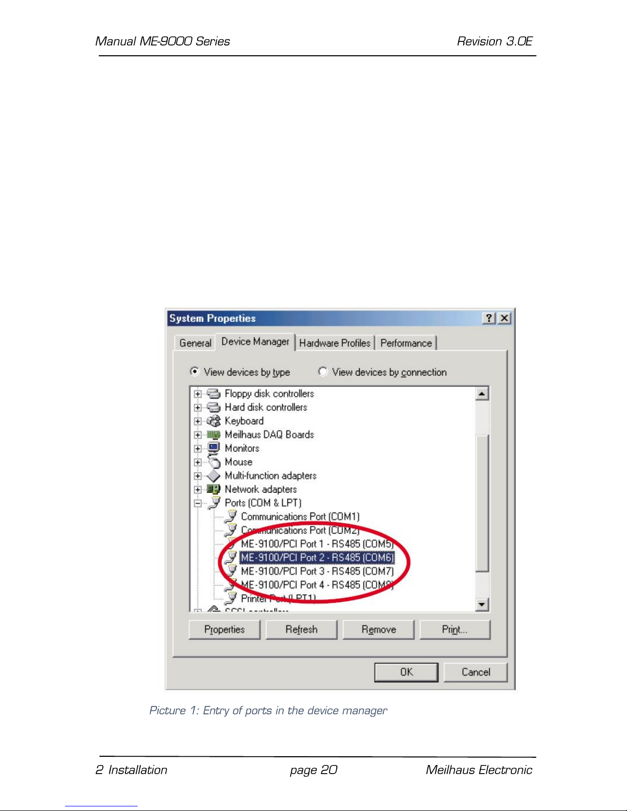
Mark the appropriate port in the device manager under „Ports“(see
Picture 1) and click the button „Properties“ in order to display the
properties.
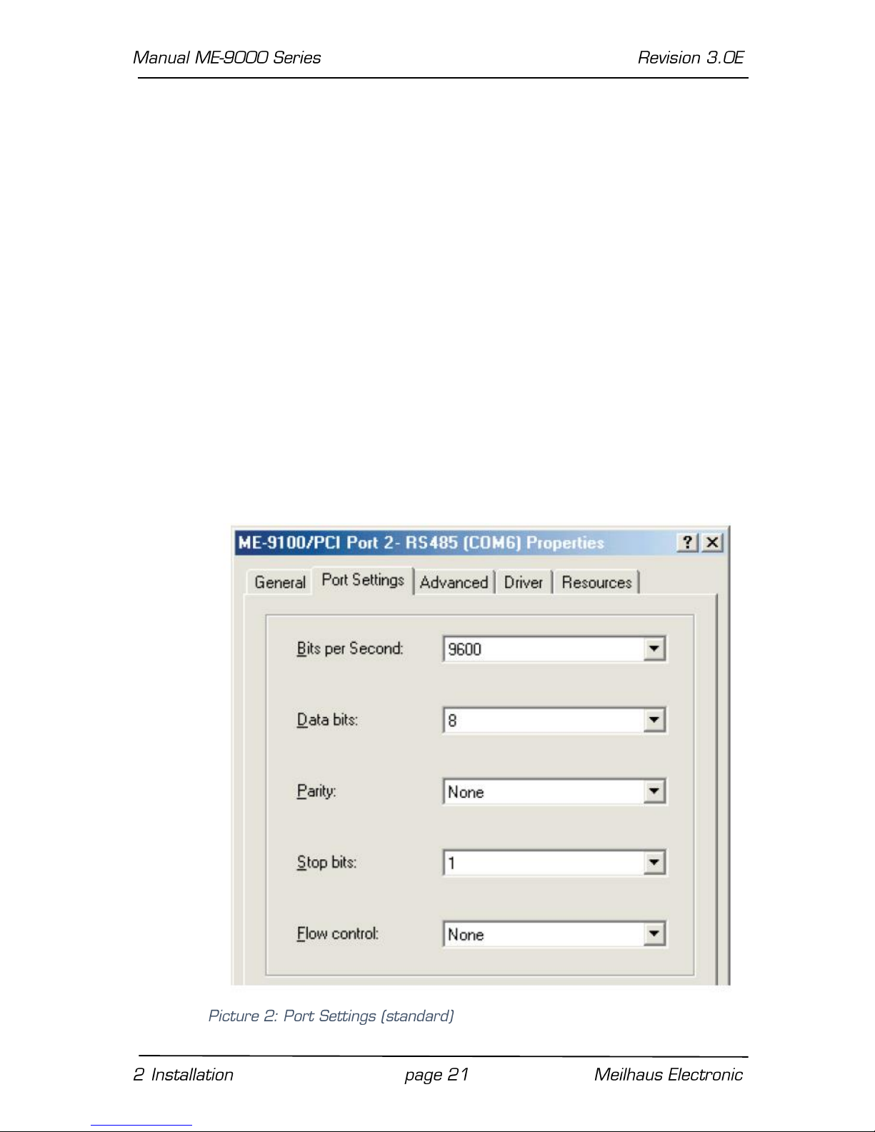
2.3.1.1 Port Settings
For most of the application programs the „Port Settings“ done in
the device manager are not relevant. Exception: board-specific
parameters like the operation mode (see 2.3.1.2 Settings
„Advanced“). Therefore check the transfer parameters in your
application program (e.g. Hyper Terminal). The following settings
are possible:
Bits per Second: depending on board version all settings
selectable in Windows up to 921,6 kbps (see also
appendix A "Specifications", page 100)
Data bits: 4; 5; 6; 7; 8
Parity: None, Odd, Even, Mark, Space
Stop bits: 1; 1,5; 2
Flow control Xon/Xoff, Hardware, None
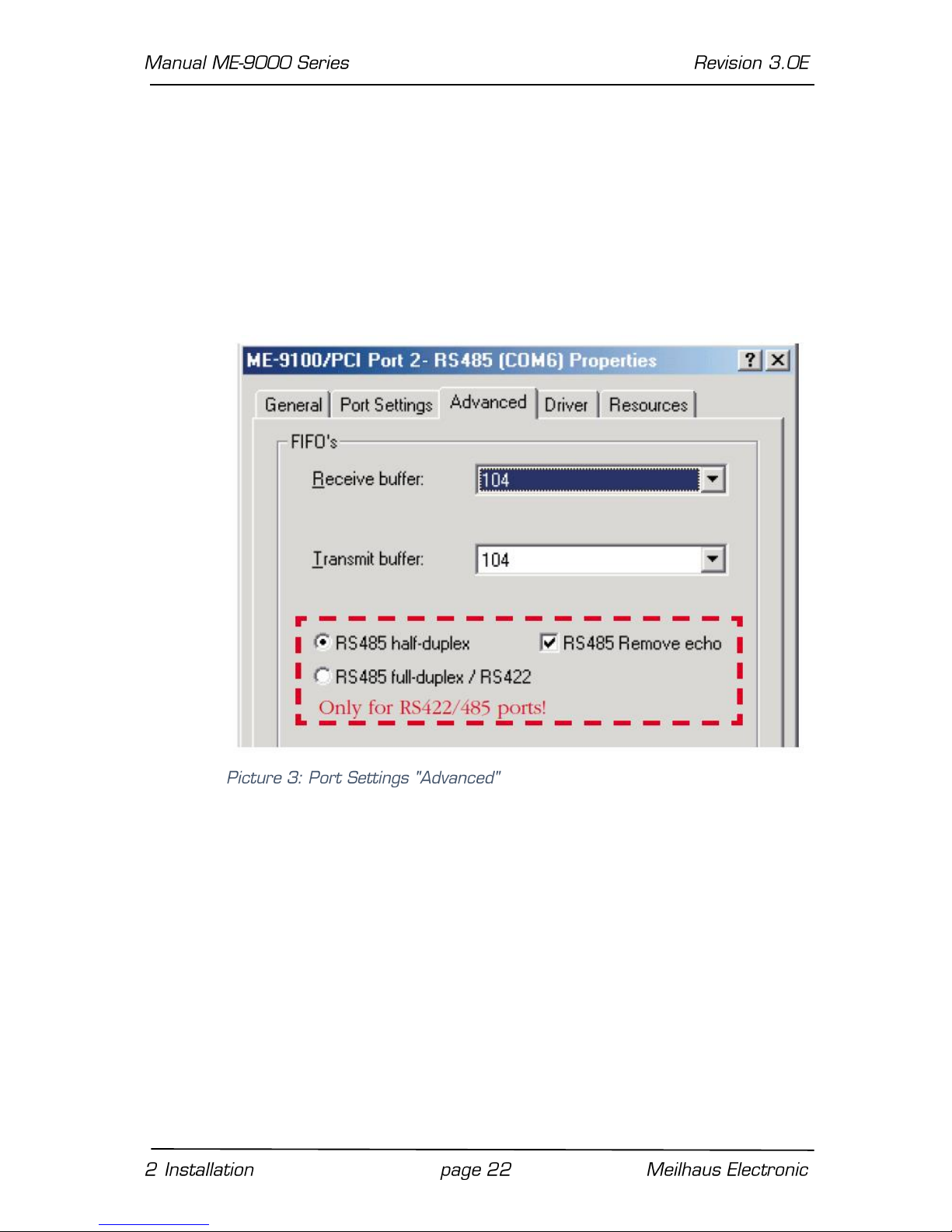
2.3.1.2 Settings „Advanced“
The property page „Advanced“ offers you the ability to set the
operation mode of RS422/485 ports (see chap 3.7 Operation
Modes) and the FIFO trigger level. Every port provides separate
transmit and receive FIFOs. Each of them with a size of 128 bytes
(ME-9100/9300). For adaption to your system there is the
possibility to set the trigger level for reading resp. writing the
FIFO. When the trigger level is matched an interrupt occurs. For
most applications the default setting is useful.
2.3.2 …under Windows 2000/XP
Use the device manager to check the port assignments and change
the settings. Choose:
o Under Windows 2000:
START-Menu ➜ Settings ➜ System Control ➜
System ➜ System Properties ➜ Hardware ➜
Device Manager
o Under Windows XP:
START-Menu ➜ Settings ➜ Performance and
Maintenance ➜ System ➜ Hardware ➜ Device
Manager
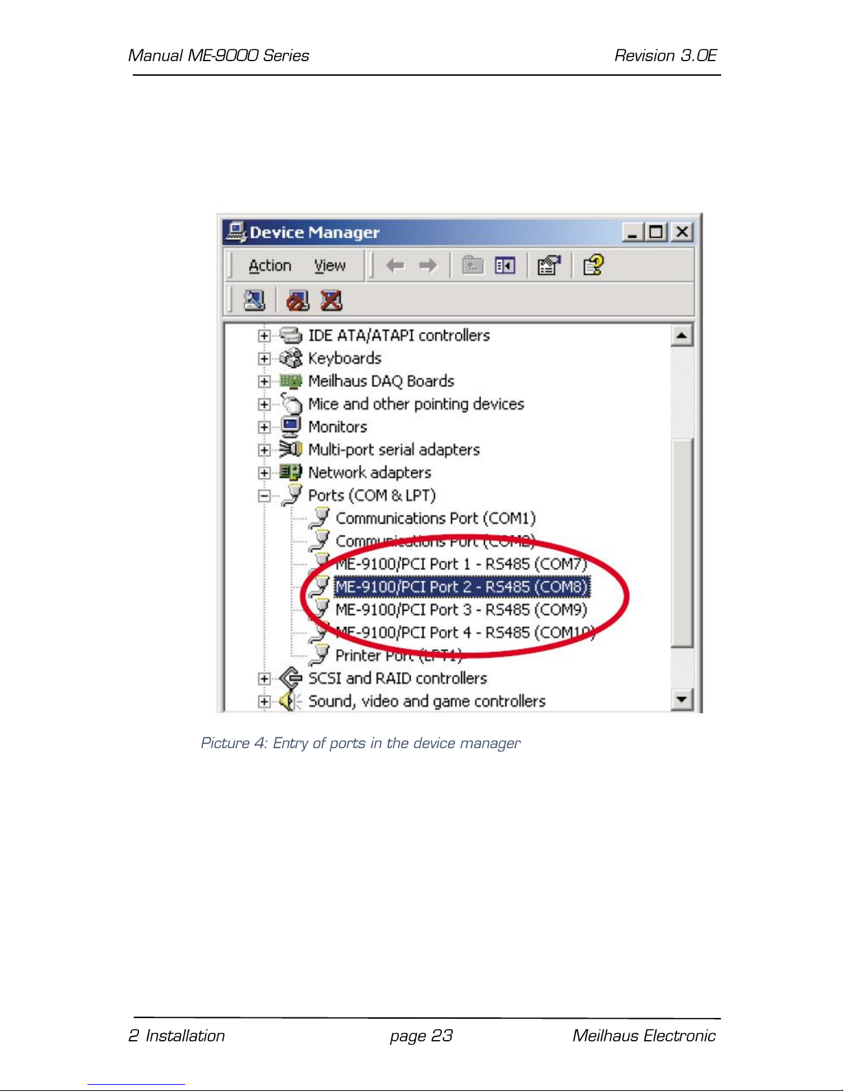
The ports of the ME-9000/9100/9300 as well as the ME-90 PC/
104-Plus will be added under „Ports (COM & LPT)“ and the COM
ports automatically assigned. In the following picture you see a
typical installation of a ME-9100 with 4 ports for RS-485
operation:
Mark the appropriate port in the device manager under “Ports”
(see picture 4) and click the button “Properties” to display the
settings.
2.3.2.1 Port Settings
For most of the application programs the „Port Settings“ done in
the device manager are not relevant. Exception: board-specific
parameters like the operation mode (see chap. 2.3.2.2). Therefore
check the transfer parameters in your application program (e.g.
Hyper Terminal). The following settings are possible:
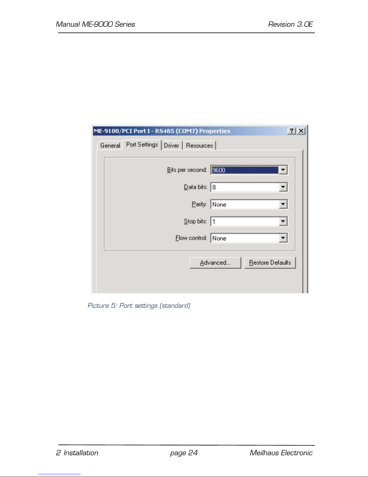
Bits per Second: depending on board version all settings
selectable in Windows up to 921,6 kbps (see also
appendix A "Specifications", page 100)
Data bits: 4; 5; 6; 7; 8
Parity: None, Odd, Even, Mark, Space
Stop bits: 1; 1,5; 2
Flow control Xon/Xoff, Hardware, None
2.3.2.2 Settings “Advanced”
The property page „Advanced“ (see picture 5) offers you the ability
to set the operation mode of RS422/485 ports (see chap 3.7
Operation Modes) and the FIFO trigger level. Every port
provides separate transmit and receive FIFOs. Each of them with a
size of 64 byte (ME-9000 and ME-90 PC/104-Plus) resp.128 bytes
(ME-9100/9300). For adaption to your system there is the
possibility to set the trigger level for reading resp. writing the
FIFO. When the trigger level is matched an interrupt occurs. For
most applications the default setting is useful.
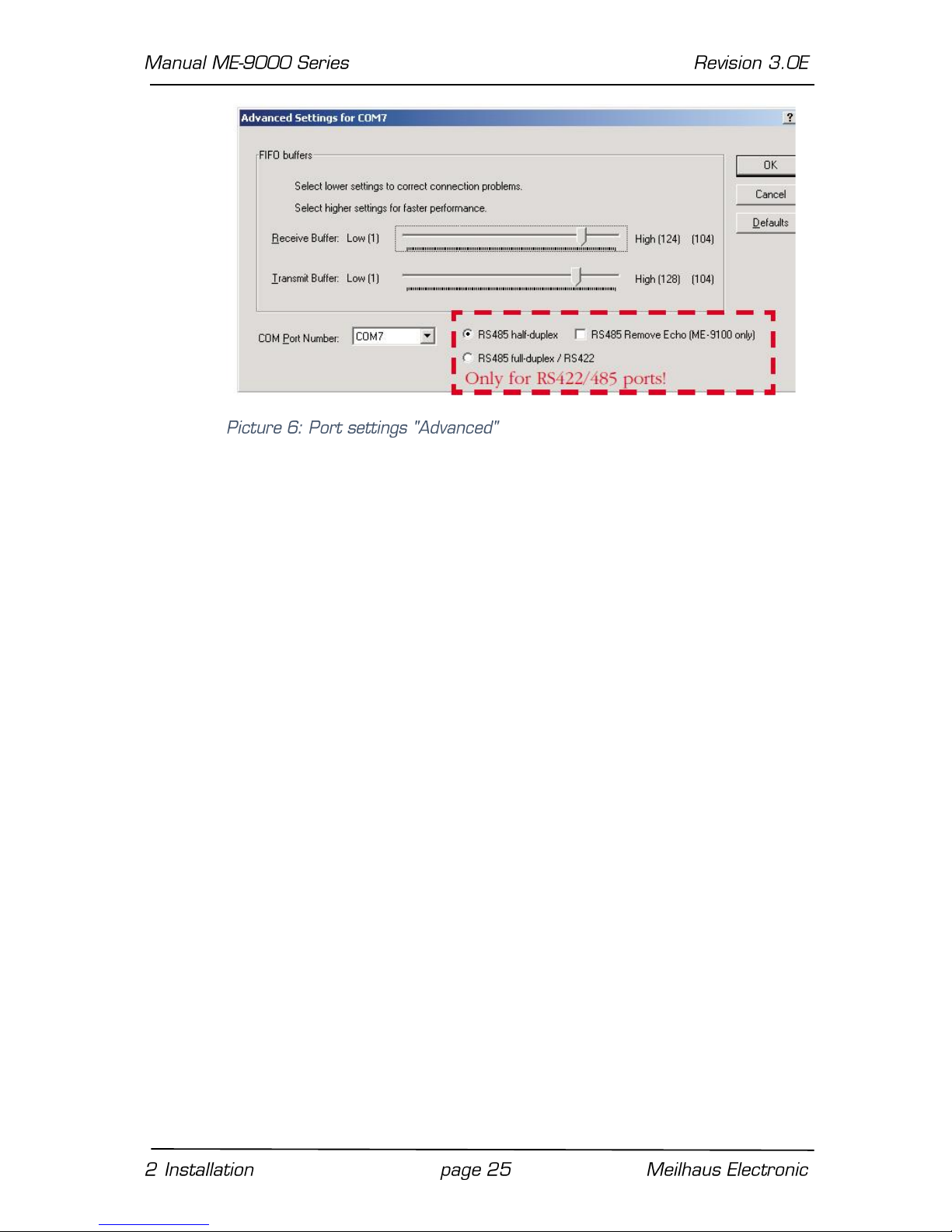
We recommend not to change the assignment of the COM ports by
the pull-down menu “COM Port Number”.
2.3.3 …under Windows NT 4.0
The assignment of COM ports is done automatically by the
operation system. Under „Control Panel“ double-click the icon „ME
SIO Ports“ to check the port assignments and change the
settings.
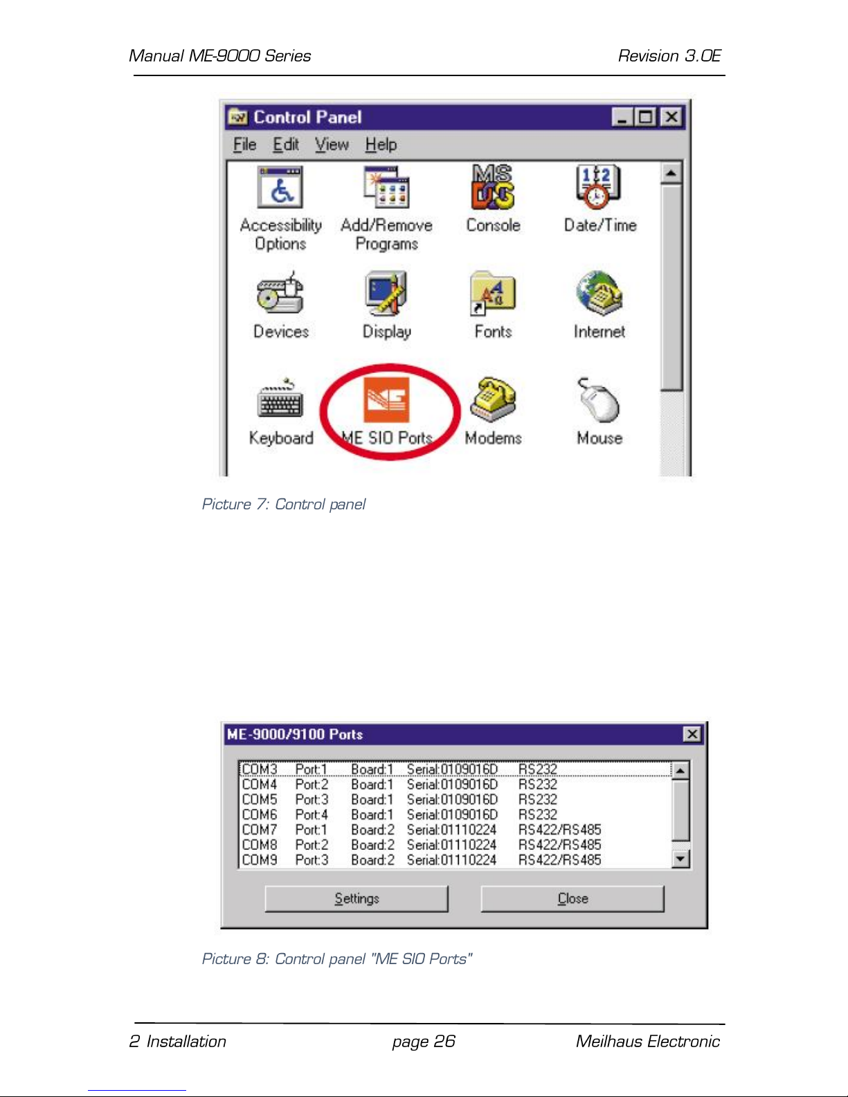
In the following picture you see a typical installation of two boards,
the first one with 4 RS-232 ports and the second one with 4 RS485 ports. You get the following information:
Beginning from the left side the name is displayed which refers to
the port, followed by the assignment of the port number to the
board, the corresponding serial number and last the interface
standard (RS232 or RS485). COM10 is not visible on the picture.

2.3.3.1 Settings “ME SIO Ports”
Mark a port in the control panel „ME SIO Ports“ (see Picture 8)
and click the button „Settings“. The next dialog offers you the
ability to set the operation mode of RS422/485 ports (see chap.
3.7 Operation Modes) and the FIFO trigger level. Every port
provides separate transmit and receive FIFOs. Each of them with a
size of 64 bytes (ME-9000 and ME-90 PC/104-Plus) resp.128
bytes (ME-9100/9300). For adaption to your system there is the
possibility to set the trigger level for reading resp. writing the
FIFO. When the trigger level is matched an interrupt occurs. For
most applications the default setting is useful. (RX Buffer =
Receive FIFO and TX Buffer = Transmit FIFO.
2.3.3.2 Port Settings
For most of the application programs the settings done in the
control-panel „Ports“ are not relevant. Exception: board-specific
parameters like the operation mode (see chap. 2.3.3.1 Settings

“ME SIO Ports”). Therefore check the transfer parameters in your
application program (e.g. Hyper Terminal). The following settings
are possible:
Bits per Second: depending on board version all settings
selectable in Windows up to 921,6 kbps (see also
appendix A "Specifications", page 101)
Data bits: 4; 5; 6; 7; 8
Parity: None, Odd, Even, Mark, Space
Stop bits: 1; 1,5; 2
Flow control Xon/Xoff, Hardware, None
3 Hardware
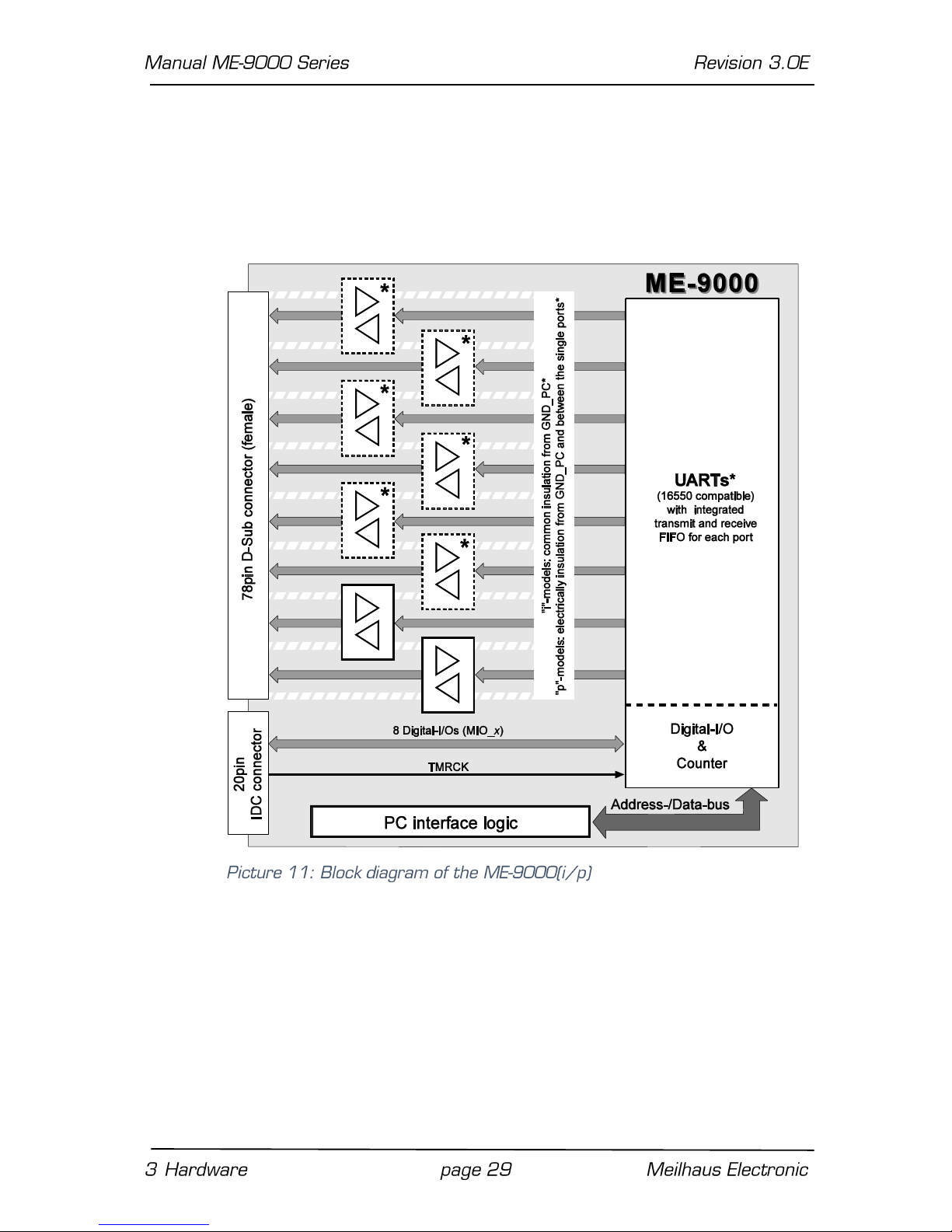
3.1 Block Diagram ME-9000
*2, 4 or 8 RS-232 and/or RS-422/485 ports
depending
on
version.
Optional:
„i“-models: with a
common electrical insulation
from PC
ground.
„p“-models:
with
electrical insulation
from PC
ground
and
between
the ports
(„island-ports“).
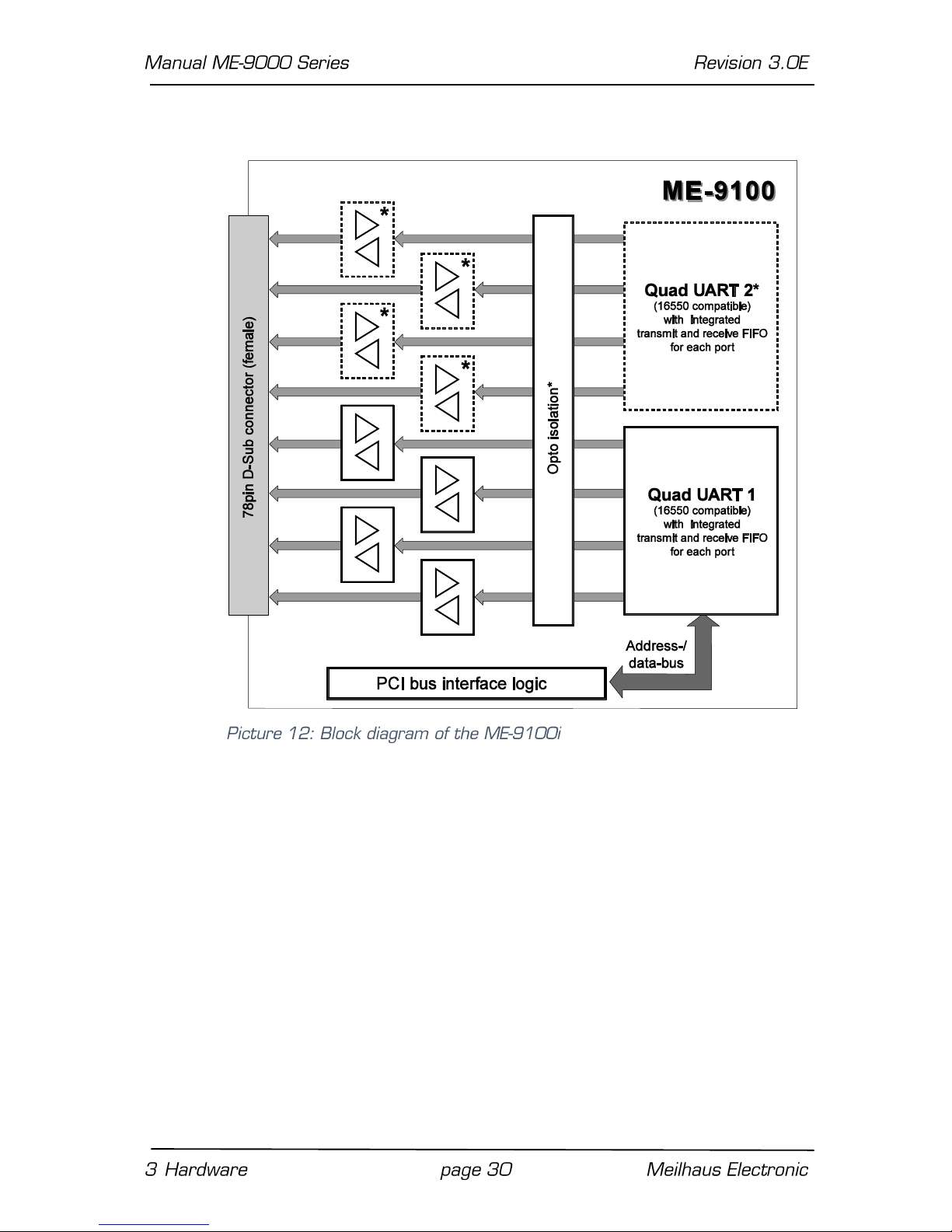
3.2 Block Diagram ME-9100
*2, 4 or 8 RS-232 and/or RS-422/485 ports depending on version.
 Loading...