

Page 1
Meilhaus Electronic Manual
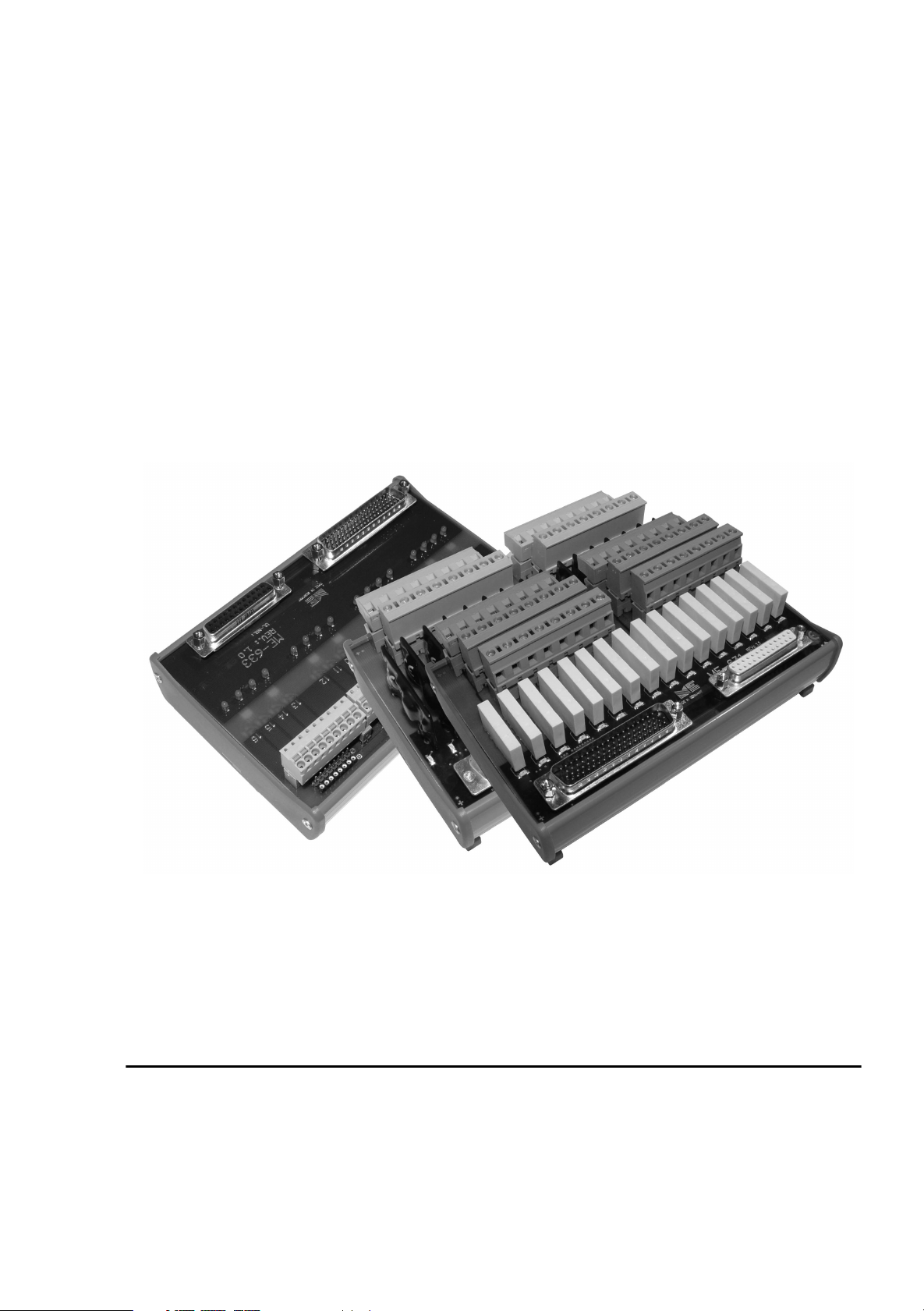
ME-63Xtend Series
1.2E
External Extension Board Series
Page 2

Imprint
Manual ME-63Xtend Series
Revision 1.2E
Revised: 23. Januar 2006
Meilhaus Electronic GmbH
Fischerstraße 2
D-82178 Puchheim/Munich
Germany
http://www.meilhaus.com
© Copyright 2006 Meilhaus Electronic GmbH
All rights reserved. No part of this publication may be reproduced or distributed
in any form whether photocopied, printed, put on microfilm or be stored in any
electronic media without the expressed written consent of Meilhaus Electronic
GmbH.
Important note:
The information contained in this manual has been reviewed with great care and
is believed to be complete and accurate. Meilhaus Electronic assumes no responsibility for its use, any infringements of patents or other rights of third parties
which may result from use of this manual or the product. Meilhaus Electronic assumes no responsibility for any problems or damage which may result from errors
or omissions. Specifications and instructions are subject to change without notice.
Borland Delphi is a trademark of Borland International Inc.
Turbo/Borland C is a trademark of Borland International Inc.
Visual C++ and Visual Basic are trademarks of the Microsoft Corporation.
VEE Pro and VEE OneLab are trademarks of Agilent Technologies.
ME-VEC and ME-FoXX are trademarks of Meilhaus Electronic.
Other company names and product names found in the text of this manual are
also trademarks of the companies involved.
Page 3

Manual ME-63Xtend Series Rev. 1.2E
Table of Contents
1 Introduction ........................................................................................ 5
1.1 Warning ...................................................................................... 5
1.2 Package contents........................................................................ 5
2 Hardware ............................................................................................. 7
2.1 ME-631......................................................................................... 9
2.1.1 Block Diagram....................................................................... 10
2.1.2 Protection Circuit ................................................................. 10
2.1.3 Pinout..................................................................................... 12
2.2 ME-632....................................................................................... 13
2.2.1 Block Diagram ..................................................................... 14
2.2.2 Jumper Settings ..................................................................... 15
2.2.3 Pinout..................................................................................... 16
2.3 ME-633....................................................................................... 17
2.3.1 Block Diagram ..................................................................... 18
2.3.2 Jumper Settings ..................................................................... 19
2.3.3 Pullup Resistors .................................................................... 20
2.3.4 Pinout..................................................................................... 21
2.4 ME-634....................................................................................... 22
2.4.1 Block Diagram ..................................................................... 23
2.4.2 Jumper Settings .................................................................... 24
2.4.3 Pullup Resistors .................................................................... 25
2.4.4 Pinout..................................................................................... 26
2.5 ME-635....................................................................................... 27
2.5.1 Block Diagram ..................................................................... 28
2.5.2 Pinout..................................................................................... 29
2.6 Connection Options................................................................. 30
2.6.1 Connection to ME-1000 ....................................................... 30
2.6.2 Connection to ME-1400 ....................................................... 32
2.6.3 Connection to ME-Boards with extra port ..................... 33
Appendix.................................................................................................. 34
A Pinouts ..................................................................................... 34
A1 Pinout ST1 .............................................................................. 34
A2 Pinout ST2 .............................................................................. 35
Meilhaus Electronic Page 3 Table of Contents
Page 4

Rev. 1.2E Manual ME-63Xtend Series
B Specifications ........................................................................... 36
B1 ME-63Xtend Series (all models) ............................................ 36
B2 ME-631 ................................................................................... 37
B3 ME-632 ................................................................................... 39
B4 ME-633 ................................................................................... 41
B5 ME-634 .................................................................................. 43
B6 ME-635 .................................................................................. 43
C Accessories................................................................................ 45
D Technical Questions................................................................. 46
D1 Fax-Hotline ............................................................................. 46
D2 Service address....................................................................... 46
E Index ......................................................................................... 47
Table of Contents Page 4 Meilhaus Electronic
Page 5

Manual ME-63Xtend Series Rev. 1.2E
1 Introduction
Valued customer,
Thank you for purchasing this Meilhaus product. You have chosen a high quality board that left our premises in a fully functional
and new condition.
Take the time to carefully examine the contents of the package
for any loss or damage that may have occurred during shipping.
If there are any items missing or if an item is damaged, contact
Meilhaus Electronic immediately.
1.1 Warning
The device was developed and produced in accordance to the
EMC low voltage directive 73/23/EWG. When putting the device
!
into operation especially with voltages greater than 42 V please
follow the appropriate standards, installation instructions and national safty standards. Meilhaus Electronic GmbH assumes no responsibility for damage in case of faulty installation, operation or
handling.
1.2 Package contents
We take great care to make sure that the package is complete in
every way. We do ask that you take the time to examine the contents of the box.
Your box should consist of:
• External extension board of the ME-63Xtend series
• Manual in PDF format on CD-ROM (optional as printed
version)
• additionally:
- ME-632: 19 jumpers
- ME-633: 19 jumpers, 4 resistor arrays
- ME-634: 18 jumpers, 2 resistor arrays
Meilhaus Electronic Page 5 Introduction
Page 6

Rev. 1.2E Manual ME-63Xtend Series
Introduction Page 6 Meilhaus Electronic
Page 7
Manual ME-63Xtend Series Rev. 1.2E
2 Hardware
The ME-63Xtend series consists of external extension boards
for DIN rail mounting. The series includes the following models:
Model
ME-631
16 relays form C,
Description Page
9
up to 6A, 30VDC/240VAC
ME-632
16 opto-isolated digital inputs
13
(2,5…60V)
ME-633
16 opto-isolated digital outputs,
17
up to 60V (Open Collector)
ME-634
8 opto-isolated digital inputs
22
(2,5…60V), 8 opto-isolated digital outputs up to 60V (Open Collector)
ME-635
16 electronic power relays, 5A/240VAC 27
Table 1: Model Overview ME-63Xtend Series
The opto-isolated I/Os of the models ME-632, ME-633 and
ME-634 are isolated up to 2500 VAC
eff
.
The ME-63Xtend series can be connected with many multi-I/O
and digital-I/O boards using appropriate connection cables. The
I/O-board requires at least two 8-bit TTL input resp. output ports.
For the following boards preconfigured cables are available:
ME-1000
ME-1400(A/B)
ME-630 series
ME-4600 series
ME-6000 series
Note: A detailed description of the connection options can be found in chapter
2.6 on page 30. Many other multi-I/O and digital-I/O boards with appropriate
TTL ports can be connected by special cables!
Special cable ME AK-D78/1000
(ME-1000 can not be combined with the ME-634!)
1:1 connection cable e.g. ME AK-D78(/1)
Special cable ME AK-D2578/4000 via additional mounting bracket for bi-directional ports (ME-630 USB:
direct connection to the 25pin D-Sub jack of the device)
Table 2: Compatible I/O boards
Meilhaus Electronic Page 7 Hardware
Page 8

Rev. 1.2E Manual ME-63Xtend Series
Attention : Make sure that no contact with voltage carrying parts
can happen by the wiring of the board. The external connections
to the board should only be made or removed in a powered
down state.
Look for proper connection of the cable. It must join the Sub-D
jack completly and must be fixed with the both screws. Otherwise a proper operation of the board can not be guaranteed!
Hardware Page 8 Meilhaus Electronic
Page 9
P x
Manual ME-63Xtend Series Rev. 1.2E
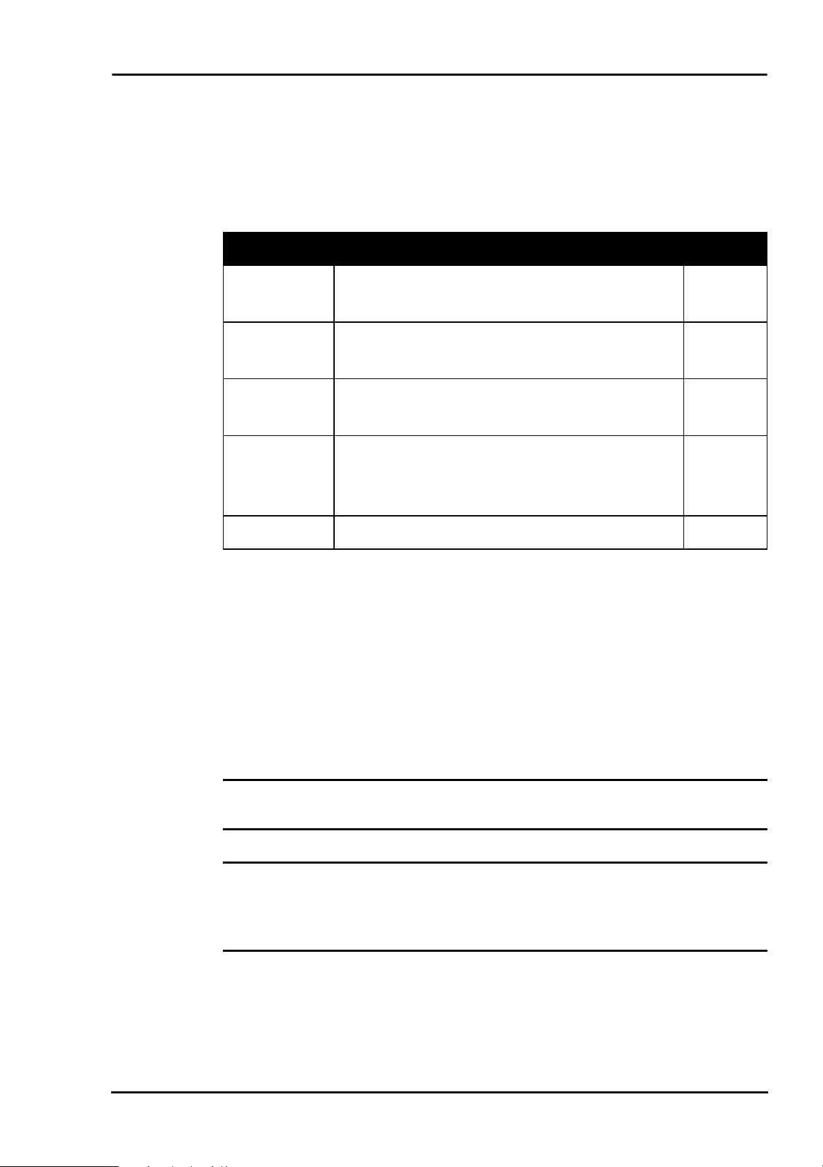
2.1 ME-631
The ME-631 is an external relay board with 16 change-over
relays (form C). The relays can switch up to 30 VDC/6 A or
240 VAC/6 A (specifications see page 37). To drive the relays a
buffer circuit is inserted. For status control one LED per channel
is assembled. It is connected in parallel to the relay coil. Depending on the I/O-board further signals are feed-through to the 25pin D-Sub female connector ST2 (see table 3).
For relay control the following assignment is valid:
Relay 1…8 Relay 9…16 ST2
ME-1000
ME-1400(A/B)
ME-630 series
ME-4600 series
ME-6000 series
Table 3: Controlling the ME-631
1
KL1
KL2
1
1
KL3
0…7 P x 8…15 P x 16…31
PA0…7 PB0…7 PC0…7
counter 0…2 (only
ME-1400A/B)
DIO_C0…7 DIO_D0…7 --
DIO_C0…7 DIO_D0…7 --
DIO_A0…7 DIO_B0…7 --
8
8
8
1
KL4
KL5
1
1
KL6
8
8
8
1 2 3 4 5 6 7 8 9 10 11 12 13 14 15 16
ME-631 Rev. 1.1
ST1
ST2
Diagram 1: ME-631
Meilhaus Electronic Page 9 Hardware
Page 10
Rev. 1.2E Manual ME-63Xtend Series
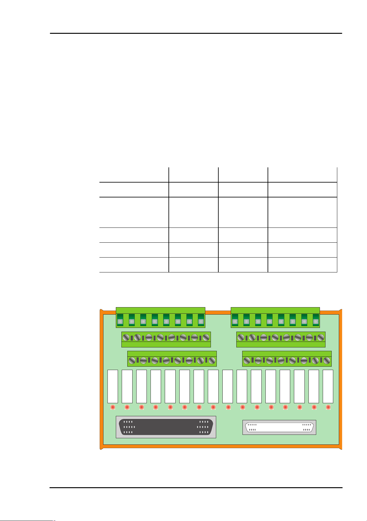
2.1.1 Block Diagram
78pin D-Sub Connector
Feed-through signals
ST1
25pin D-Sub Connector (ST2)
Diagram 2: Block diagram ME-631
8 Relays
Form C
8 Relays
Form C
NC
NO
COM
NC
NO
COM
ME-631
ME-631
8
8
8
8
8
8
KL1
KL3
KL2
KL4
KL6
KL5
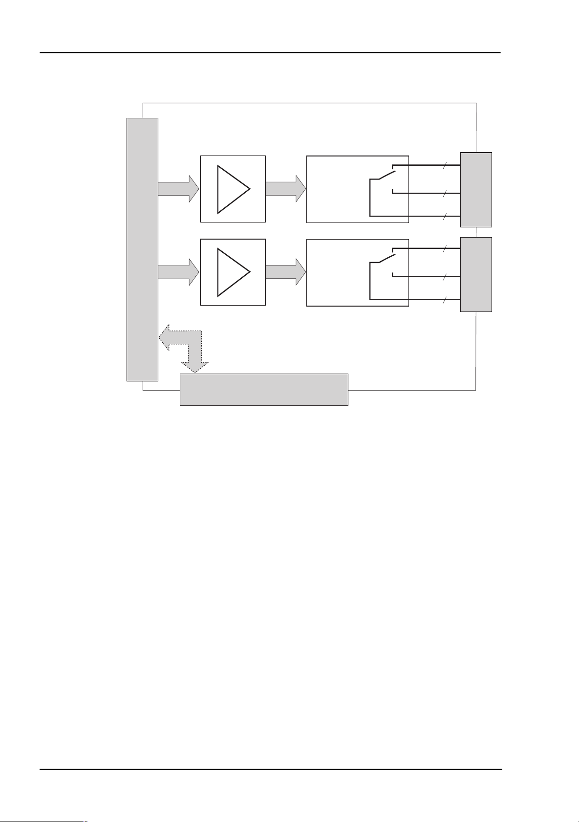
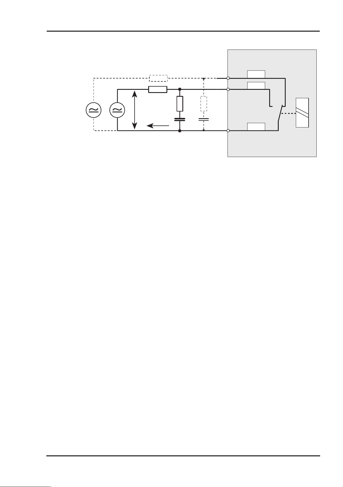
2.1.2 Protection Circuit
On the ME-631 electro-mechanical power relays are used. They
can switch currents up to 6 A. During switching the relays induced voltages and high transient currents occur. Therefore the use
of a protection circuit for the contacts is urgently needed. To
guarantee the efficiency of the protection circuit the distance
should not exceed more than 20 cm.
The following diagram shows a typical circuitry that could be
used. The values of the components used depend on the load
and the relay properties. The condensator C suppresses the discharge when contact opens and the resistor R limits the current
when switching the next time. The circuitry can be used for DC
and AC operation. The ME-631 offers a make contact as well as
a break contact. Therefore the protection circuit must be provided for every contact switching a considerable load.
Hardware Page 10 Meilhaus Electronic
Page 11
Manual ME-63Xtend Series Rev. 1.2E
Resistive or
inductive loads
RL*_B
RL*_A
R
1
R
2
U
C
I
1
C
2
Diagram 3: Protection circuit
As a rule for selection of R
R
: 0,5 bis 1 Ω per 1 V of switching voltage U
x
C
: 0,5 bis 1 µF per 1 A of switching current I
x
and C
x
use:
x
RL*_C
Meilhaus Electronic Page 11 Hardware
Page 12
Rev. 1.2E Manual ME-63Xtend Series
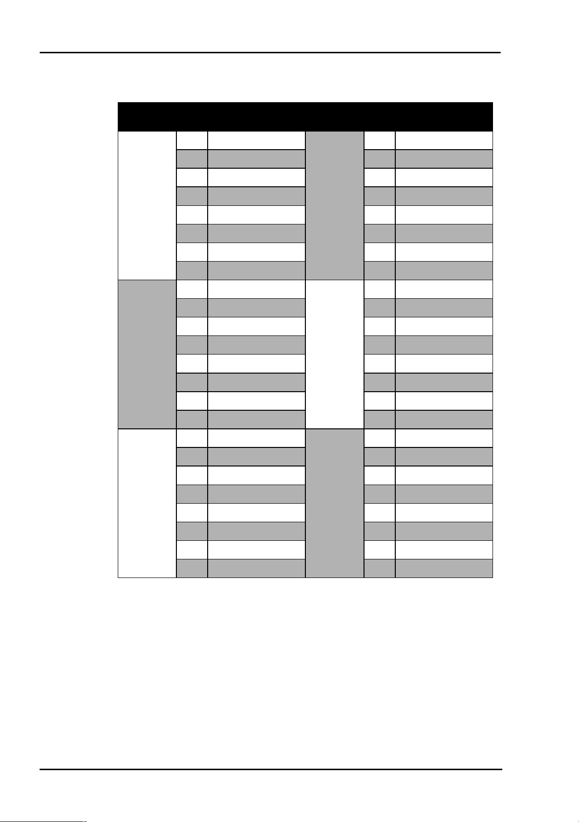
2.1.3 Pinout
Clamping
block
KL1
KL2
Pin
1 Relay 1, NC
2 Relay 2, NC 2 Relay 10, NC
3 Relay 3, NC 3 Relay 11, NC
4 Relay 4, NC 4 Relay 12, NC
5 Relay 5, NC 5 Relay 13, NC
6 Relay 6, NC 6 Relay 14, NC
7 Relay 7, NC 7 Relay 15, NC
8 Relay 8, NC 8 Relay 16, NC
1 Relay 1, COM
2 Relay 2, COM 2 Relay 10, COM
3 Relay 3, COM 3 Relay 11, COM
4 Relay 4, COM 4 Relay 12, COM
5 Relay 5, COM 5 Relay 13, COM
6 Relay 6, COM 6 Relay 14, COM
Signal
Clamping
block
KL4
KL5
Pin
1 Relay 9, NC
1 Relay 9, COM
Signal
7 Relay 7, COM 7 Relay 15, COM
8 Relay 8, COM 8 Relay 16, COM
1 Relay 1, NO
2 Relay 2, NO 2 Relay 10, NO
3 Relay 3, NO 3 Relay 11, NO
KL3
4 Relay 4, NO 4 Relay 12, NO
5 Relay 5, NO 5 Relay 13, NO
6 Relay 6, NO 6 Relay 14, NO
7 Relay 7, NO 7 Relay 15, NO
8 Relay 8, NO 8 Relay 16, NO
Table 4: Pinout ME-631
NC: „Normally Closed“
NO: „Normally Open“
COM: „Common“
1 Relay 9, NO
KL6
Hardware Page 12 Meilhaus Electronic
Page 13
Manual ME-63Xtend Series Rev. 1.2E
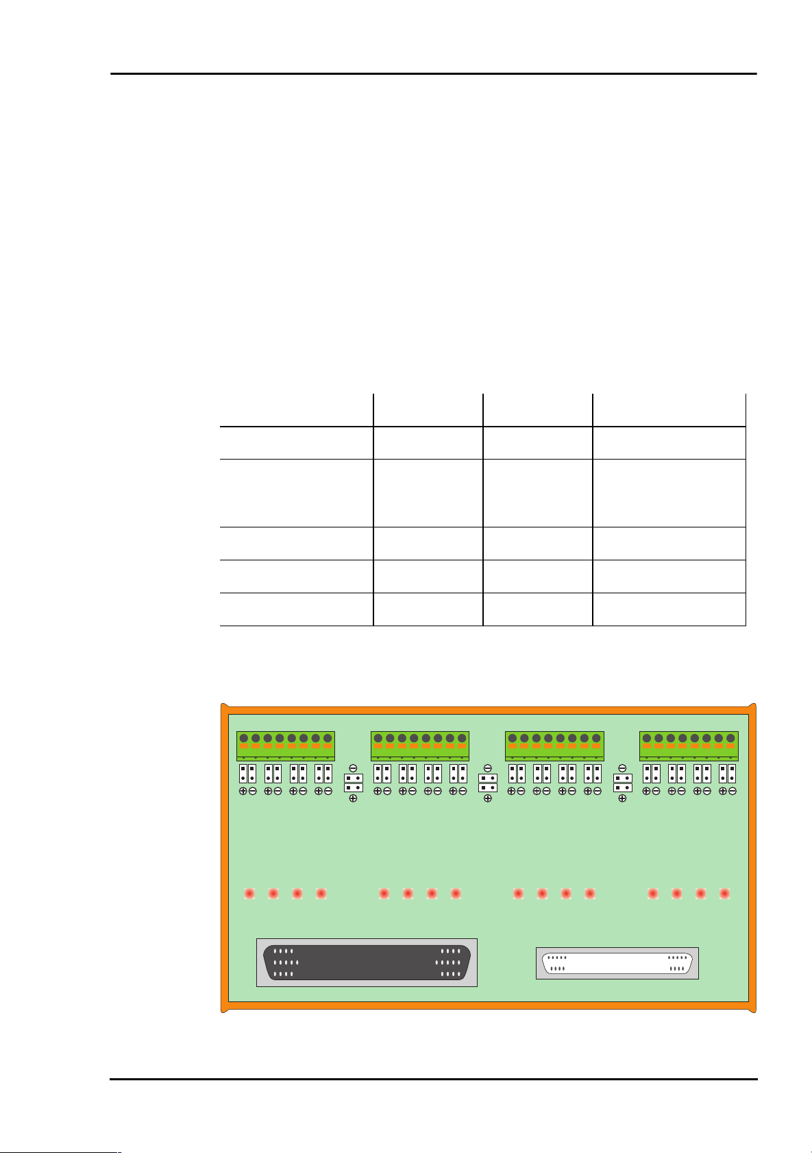
2.2 ME-632
The ME-632 is an external extension board with 16 opto-isolated digital input channels. The voltage high-level can be in the
range of 2.5…60V (specifications see page 39). For each channel
the positive and negative input is connected with the clamp. The
4 channels of a clamp are combined in a group. For status control
one LED per channel is assembled after the input buffer. Depending on the I/O-board further signals are feed-through to the 25pin D-Sub female connector ST2 (see table 5).
For the inputs the following assignment is valid:
Input 1…8 Input 9…16 ST2
ME-1000
ME-1400(A/B)
ME-630 series
ME-4600 series
ME-6000 series
Table 5: Controlling the ME-632
KL1 KL2 KL3 KL4
JP17a
JP1a
JP1b
JP2a
JP2b
JP3a
JP3b
JP4a
JP4b
JP17b
Px0…7 Px8…15 Px16…31
PA0…7 PB0…7 PC0…7
counter 0…2 (only
ME-1400A/B)
DIO_C0…7 DIO_D0…7 --
DIO_C0…7 DIO_D0…7 --
DIO_A0…7 DIO_B0…7 --
JP19a
JP19b
18181818
JP13a
JP5a
JP5b
JP6a
JP6b
JP7a
JP7b
JP8a
JP8b
JP18a
JP18b
JP9a
JP9b
JP10a
JP10b
JP11a
JP11b
JP12a
JP12b
JP13b
JP14a
JP14b
JP15a
JP15b
JP16a
JP16b
16151413121110987654321
ME-632 Rev. 1.0
ST1
ST2
Diagram 4: ME-632
Meilhaus Electronic Page 13 Hardware
Page 14
Rev. 1.2E Manual ME-63Xtend Series
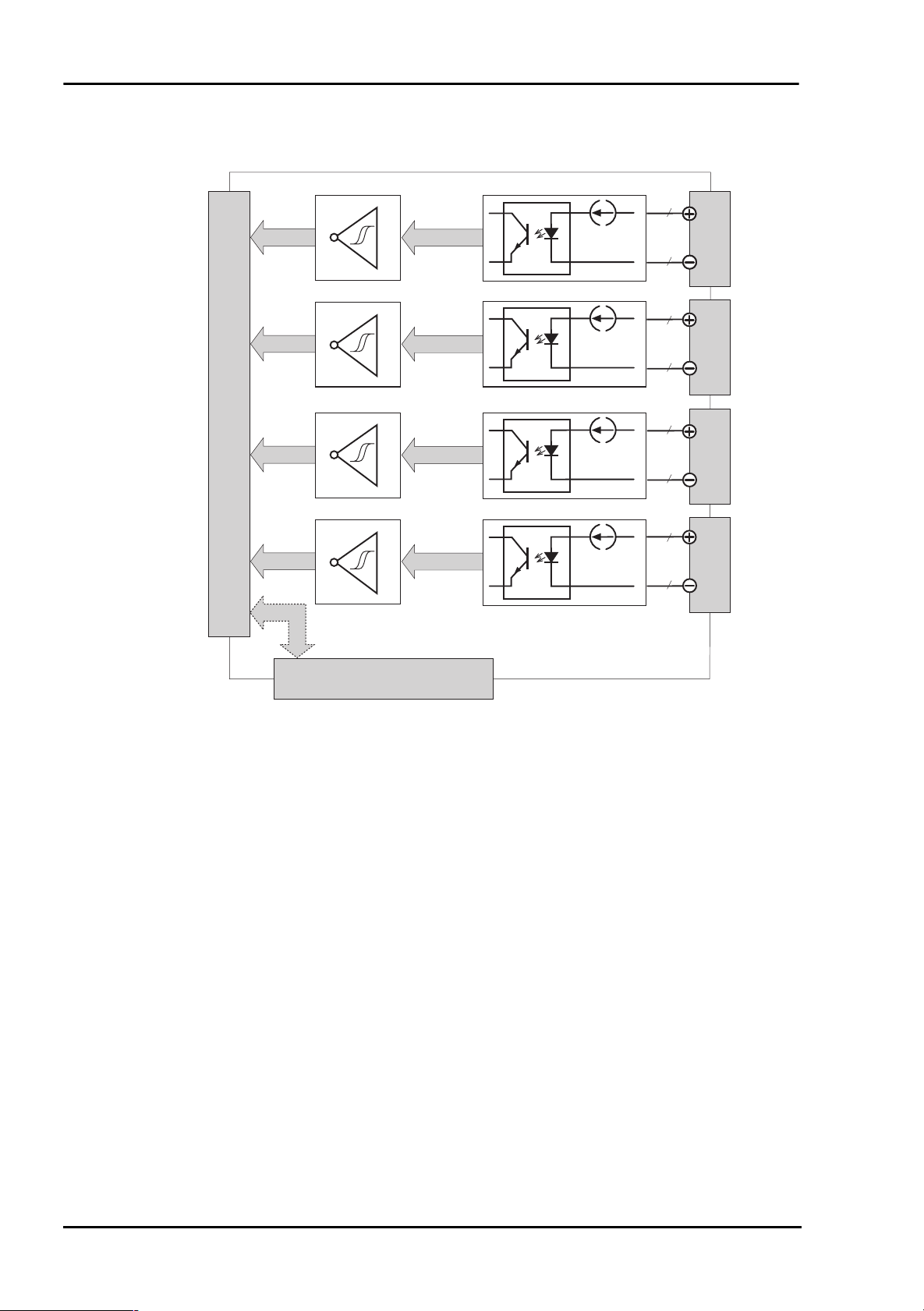
2.2.1 Block Diagram
4
I
78pin D-Sub Connector
const.
I
const.
I
const.
KL1
4
4
KL2
4
4
KL3
4
ST1
Feed-through signals
25pin D-Sub Connector (ST2)
Diagram 5: Block diagram ME-632
4
I
const.
ME-632
ME-632
4
KL4
Hardware Page 14 Meilhaus Electronic
Page 15
Manual ME-63Xtend Series Rev. 1.2E
2.2.2 Jumper Settings
By jumper a common reference can be made between the involved channels of a group (see diagram 6).
The input channels can be refered alternatively to a positive
reference voltage or to a common ground. For every channel,
which should be refered to a positive reference, the corresponding jumper JPxa must be set. For every channel, which should
be refered to ground, the corresponding jumper JPxb must be set.
For example: if the jumpers JP1a and JP3a are set you can connect the positive reference of group KL1 to the clamps KL1.1 or
KL1.5.
Please note, out of each pair of jumpers only one jumper (e. g.
JP1a, JP1b) may be set!
JP1a
KL1.1…
1
2
Group KL1
…KL1.8
Group KL2
KL2.1…
81
JP1b
(JP2x…4x) (JP6x…8x)
JP5a
JP17a
JP17b
JP5b
1
2
…KL2.8
81
JP18a
JP18b
JP9a
KL3.1…
1
2
Group KL3
…KL3.8
81
JP9b
(JP10x…12x) (JP14x…16x)
JP13a
JP19a
JP19b
KL4.1…
1
2
Group KL4
…KL4.8
81
JP13b
Diagram 6: Jumper ME-632
If required, alternatively the positive references (JP17a, JP18a,
JP19a) or the ground references (JP17b, JP18b, JP19b) of adjacent
groups can be connected with each another.
Meilhaus Electronic Page 15 Hardware
Page 16

Rev. 1.2E Manual ME-63Xtend Series
2.2.3 Pinout
Clamping
block
KL1
KL3
Pin Signal
1 Input 1, positive
2 Input 1, negative 2 Input 5, negative
3 Input 2, positive 3 Input 6, positive
4 Input 2, negative 4 Input 6, negative
5 Input 3, positive 5 Input 7, positive
6 Input 3, negative 6 Input 7, negative
7 Input 4, positive 7 Input 8, positive
8 Input 4, negative 8 Input 8, negative
1 Input 9, positive
2 Input 9, negative 2 Input 13, negative
3 Input 10, positive 3 Input 14, positive
4 Input 10, negative 4 Input 14, negative
5 Input 11, positive 5 Input 15, positive
6 Input 11, negative 6 Input 15, negative
Clamping
block
KL2
KL4
Pin Signal
1 Input 5, positive
1 Input 13, positive
7 Input 12, positive 7 Input 16, positive
8 Input 12, negative 8 Input 16, negative
Table 6: Pinout ME-632
Hardware Page 16 Meilhaus Electronic
Page 17

Manual ME-63Xtend Series Rev. 1.2E
2.3 ME-633
The ME-633 is an external extension board with 16 opto-isolated digital output channels. The outputs are designed as open
collector outputs and can switch up to 60V (specifications see
page 41). For each channel the positive and negative output is
connected with the clamp. The 4 channels of a clamp are combined in a group. For status control one LED per channel is assembled before the opto-isolation. Depending on the I/O-board
further signals are feed-through to the 25-pin D-Sub female connector ST2 (see table 7).
For the outputs the following assignment is valid:
Output 1…8 Output 9…16 ST2
ME-1000
ME-1400(A/B)
ME-630 series
ME-4600 series
ME-6000 series
RA1
4123
JP…
1 10
JP17b JP19b
Px0…7 Px8…15 Px16…31
PA0…7 PB0…7 PC0…7
counter 0…2 (only
ME-1400A/B)
DIO_C0…7 DIO_D0…7 --
DIO_C0…7 DIO_D0…7 --
DIO_A0…7 DIO_B0…7 --
Table 7: Controlling the ME-633
RA2
JP…
1 9
JP18a
JP18b
8567
RA3
JP…
1 10
1291011
KL3 KL4KL1 KL2
RA4
JP…
1 9
1613 14 15
16151413121110987654321
ME-633
ST1
ST2
Rev. 1.0
Diagram 7: ME-633
Meilhaus Electronic Page 17 Hardware
Page 18

Rev. 1.2E Manual ME-63Xtend Series
2.3.1 Block Diagram
4
KL1
4
4
KL2
4
4
KL3
4
78pin D-Sub Connector
ST1
Feed-through signals
25pin D-Sub Connector (ST2)
Diagram 8: Blocks diagram ME-633
4
4
ME-633
ME-633
KL4
Hardware Page 18 Meilhaus Electronic
Page 19

Manual ME-63Xtend Series Rev. 1.2E
2.3.2 Jumper Settings
By jumper a common reference can be made between the involved channels of a group (see diagram 9).
For the output channels a common ground can be defined for
each group. For every channel, which should be refered to it, the
corresponding jumper JPx must be set. By the clamps KLx.1 the
ground reference for each group must be done. For example: if
the jumpers JP1 and JP4 are set you can connect the ground reference of group KL1 to the clamp KL1.1.
KL1.1…
R
UP
Group KL1
…KL1.10
101
JP1
1
2
(JP2…4) (JP6…8)
RA1.1
JP17b
KL2.1…
R
UP
Group KL2
JP5
1
2
RA2.1
…KL2.9
91
JP18a
JP18b
KL3.1…
R
UP
Group KL3
…KL3.10
Group KL4
KL4.1…
101
JP19b
R
UP
RA4.1
JP9
1
2
(JP10…12) (JP14…16)
RA3.1
…KL4.9
91
JP13
1
2
Diagram 9: Jumper ME-633
If required, the grounds of adjacent groups (JP17a, JP18a, JP19a)
can be connected with each another. Additionally the positive references between the groups KL2 and KL3 (JP18a) can be connected.
Meilhaus Electronic Page 19 Hardware
Page 20

Rev. 1.2E Manual ME-63Xtend Series
2.3.3 Pullup Resistors
As pullup resistors RUP (see diagram 9) resistor arrays with 4 separate resistors come with the package.
If you want to use pullup resistors a positive reference for the
groups KL1 and KL2 must be done by clamp KL1.10. For the
groups KL3 and KL4 a positive reference must be done by clamp
KL3.10. If necessary you can you use different resistor values for
each channel.
KL1.1…
1 10
1
4 x R
UP
…KL1.10
8
Diagram 10: Pullup resistors
RAx
1
Hardware Page 20 Meilhaus Electronic
Page 21

Manual ME-63Xtend Series Rev. 1.2E
2.3.4 Pinout
Clamping
block
KL1
Pin Signal
1 Ground KL1
2 Output 1, positive 2 Output 5, positive
3 Output 1, negative 3 Output 5, negative
4 Output 2, positive 4 Output 6, positive
5 Output 2, negative 5 Output 6, negative
6 Output 3, positive 6 Output 7, positive
7 Output 3, negative 7 Output 7, negative
8 Output 4, positive 8 Output 8, positive
9 Output 4, negative 9 Output 8, negative
10 positive reference
KL1 and KL2
1 Ground KL3
2 Output 9, positive 2 Output 13, positive
3 Output 9, negative 3 Output 13, negative
Clamping
block
KL2
Pin Signal
1 Ground KL2
1 Ground KL4
KL3
4 Output 10, positive 4 Output 14, positive
5 Output 10, negative 5 Output 14, negative
6 Output 11, positive 6 Output 15, positive
7 Output 11, negative 7 Output 15, negative
8 Output 12, positive 8 Output 16, positive
9 Output 12, negative 9 Output 16, negative
10 positive reference
KL3 and KL4
KL4
Table 8: Pinout ME-633
Meilhaus Electronic Page 21 Hardware
Page 22

Rev. 1.2E Manual ME-63Xtend Series
2.4 ME-634
The ME-634 is an external extension board with 8 opto-isolated
digital output channels and 8 opto-isolated digital input
channels. The outputs are designed as open collector outputs
and can switch up to 60V. The voltage high-level of the inputs
can be in the range of 2.5…60V (specifications see page 43). For
each channel the positive and negative input resp. output is connected with the clamp. The 4 channels of a clamp are combined
in a group. For status control one LED per channel is assembled.
Depending on the I/O-board further signals are feed-through to
the 25-pin D-Sub female connector ST2 (see table 9).
For the inputs resp. outputs the following assignment is valid:
Output 1…8 Input 9…16 ST2
ME-1000
ME-1400(A/B)
ME-630 series
ME-4600 series
ME-6000 series
RA1
4123
JP…
1 10
KL1 KL2
JP17
Combination not possible
PA0…7 PB0…7 PC0…7
counter 0…2 (only
ME-1400A/B)
DIO_C0…7 DIO_D0…7 --
DIO_C0…7 DIO_D0…7 --
DIO_A0…7 DIO_B0…7 --
Table 9: Controlling the ME-634
1
JP…
RA2
8567
9
KL3 KL4
1818
JP9a
JP9b
JP11a
JP11b
JP10a
JP10b
JP12a
JP12b
JP18a
JP18b
JP13a
JP13b
JP14a
JP14b
JP15a
JP15b
JP16a
JP16b
16151413121110987654321
ME-634 Rev. 1.0
ST1
ST2
Diagram 11: ME-634
Hardware Page 22 Meilhaus Electronic
Page 23

Manual ME-63Xtend Series Rev. 1.2E
2.4.1 Block Diagram
4
KL1
4
4
KL1
4
4
I
const.
78pin D-Sub Connector
KL3
4
ST1
Feed-through signals
25pin D-Sub Connector (ST2)
Diagram 12: Block diagram ME-634
4
I
const.
ME-634
ME-634
4
KL4
Meilhaus Electronic Page 23 Hardware
Page 24

Rev. 1.2E Manual ME-63Xtend Series
2.4.2 Jumper Settings
By jumper a common reference can be made between the involved channels of a group (see diagram 13).
For the output channels a common ground can be defined for
each group (KL1 resp. KL2). For every channel, which should be
refered to it, the corresponding jumper JPx must be set. By the
clamps KL1.1 resp. KL2.1 the ground reference for each group
must be done. For example: if the jumpers JP1 and JP4 are set
you can connect the ground reference of group KL1 to the clamp
KL1.1.
The input channels can be refered alternatively to a positive
reference voltage or to a common ground. For every channel,
which should be refered to a positive reference, the corresponding jumper JPxa must be set. For every channel, which should
be refered to ground, the corresponding jumper JPxb must be set.
For example: if the jumpers JP13b and JP16b are set you can connect the ground reference of group KL4 to the clamps KL4.2 or
KL4.8.
Please note, out of each pair of jumpers JPxa,b only one jumper
may be set!
KL1.1…
R
UP
Group KL1
…KL1.10
101
JP1
1
2
(JP2…4) (JP6…8) (JP10x…12x) (JP14x…16x)
RA1.1
JP17
KL2.1…
R
UP
Group KL2
JP5
1
2
RA2.1
…KL2.9
91
JP9a
KL3.1…
1
2
Group KL3
JP9b
…KL3.8
81
JP13a
JP18a
JP18b
KL4.1…
1
2
Group KL4
…KL4.8
81
JP13b
Diagram 13: Jumper ME-634
If required, the grounds of group KL1 and KL2 (JP17) can be connected. Additionally the positive references (JP18a) or the
ground references (JP18b) of KL3 and KL4 can be connected with
each another.
Hardware Page 24 Meilhaus Electronic
Page 25

Manual ME-63Xtend Series Rev. 1.2E
2.4.3 Pullup Resistors
As pullup resistors RUP for the output channels (see
diagram 14) resistor arrays with 4 separate resistors come with
the package.
If you want to use pullup resistors a positive reference for the
groups KL1 and KL2 must be done by clamp KL1.10. If necessary
you can you use different resistor values for each channel.
KL1.1…
1 10
1
4 x R
UP
…KL1.10
8
Diagram 14: Pullup resistors
RAx
1
Meilhaus Electronic Page 25 Hardware
Page 26

Rev. 1.2E Manual ME-63Xtend Series
2.4.4 Pinout
Clamping
block
KL1
Pin Signal
1 Ground KL1
2 Channel 1
(Output), positive
3 Channel 1
(Output), negative
4 Channel 2
(Output), positive
5 Channel 2
(Output), negative
6 Channel 3
(Output), positive
7 Channel 3
(Output), negative
8 Channel 4
(Output), positive
9 Channel 4
(Output), negative
Clamping
block
KL2
Pin Signal
1 Ground KL2
2 Channel 5
(Output), positive
3 Channel 5
(Output), negative
4 Channel 6
(Output), positive
5 Channel 6
(Output), negative
6 Channel 7
(Output), positive
7 Channel 7
(Output), negative
8 Channel 8
(Output), positive
9 Channel 8
(Output), negative
KL3
10 positivee reference
KL1 and KL2
1 Channel 9
(Input), positive
2 Channel 9
(Input), negative
3 Channel 10
(Input), positive
4 Channel 10
(Input), negative
5 Channel 11
(Input), positive
6 Channel 11
(Input), negative
7 Channel 12
(Input), positive
8 Channel 12
(Input), negative
KL4
1 Channel 13
(Input), positive
2 Channel 13
(Input), negative
3 Channel 14
(Input), positive
4 Channel 14
(Input), negative
5 Channel 15
(Input), positive
6 Channel 15
(Input), negative
7 Channel 16
(Input), positive
8 Channel 16
(Input), negative
Table 10: Pinout ME-634
Hardware Page 26 Meilhaus Electronic
Page 27

Manual ME-63Xtend Series Rev. 1.2E
2.5 ME-635
The ME-635 is an external relay board with 16 solid-state
relays. The relays can switch up to 5 A/240 VAC (specifications
see page 43). An automatic detection of zero-axis crossing guarantees that the load is always switched on zero-axis crossing of
your signal. However phase synchronized switching is not possible with the ME-635.For status control one LED per channel is assembled. Depending on the I/O-board further signals are feedthrough to the 25-pin D-Sub female connector ST2 (see table 11).
For controlling the relays th following assignment is valid:
Relays 1…8 Relays 9…16 ST2
ME-1000
ME-1400(A/B)
ME-630 series
ME-4600 series
ME-6000 series
Px0…7 Px8…15 Px16…31
PA0…7 PB0…7 PC0…7
DIO_C0…7 DIO_D0…7 --
DIO_C0…7 DIO_D0…7 --
DIO_A0…7 DIO_B0…7 --
Table 11: Controlling the ME-635
18
KL1
KL2
1
2 3 4 5 6 7 8 9 10 11 12 13 14 15 161
8
18
KL3
KL4
1
counter 0…2 (only
ME-1400A/B)
8
ME-635
ST1
Rev. 1.0
ST2
Diagram 15: ME-635
Meilhaus Electronic Page 27 Hardware
Page 28

Rev. 1.2E Manual ME-63Xtend Series
2.5.1 Block Diagram
78pin D-Sub Connector
Feed-through signals
ST1
25pin D-Sub Connector (ST2)
Diagram 16: Block diagram ME-635
8 solid-state relays
8 solid-state relays
ME-635
ME-635
COM
NO
COM
NO
8
KL1
8
KL2
8
KL3
8
KL4
Hardware Page 28 Meilhaus Electronic
Page 29

Manual ME-63Xtend Series Rev. 1.2E
2.5.2 Pinout
Clamping
block
KL1
KL3
Pin Signal
1 Relay 1, COM
2 Relay 2, COM 2 Relay 2, NO
3 Relay 3, COM 3 Relay 3, NO
4 Relay 4, COM 4 Relay 4, NO
5 Relay 5, COM 5 Relay 5, NO
6 Relay 6, COM 6 Relay 6, NO
7 Relay 7, COM 7 Relay 7, NO
8 Relay 8, COM 8 Relay 8, NO
1 Relay 9, COM
2 Relay 10, COM 2 Relay 10, NO
3 Relay 11, COM 3 Relay 11, NO
4 Relay 12, COM 4 Relay 12, NO
5 Relay 13, COM 5 Relay 13, NO
6 Relay 14, COM 6 Relay 14, NO
Clamping
block
KL2
KL4
Pin Signal
1 Relay 1, NO
1 Relay 9, NO
7 Relay 15, COM 7 Relay 15, NO
8 Relay 16, COM 8 Relay 16, NO
Table 12: Pinout ME-635
NO: „Normally Open“
COM: „Common“
Meilhaus Electronic Page 29 Hardware
Page 30

Rev. 1.2E Manual ME-63Xtend Series
2.6 Connection Options
For the connection of the ME-63Xtend series to the ME-1000,
ME-1400, ME-630, ME-4600 series and ME-6000 series ready-made cables are available as accessories from Meilhaus Electronic
(see the following chapters).
Using individual connection cables the ME-63Xtend series can
also be connected to many multi-I/O and digital-I/O boards. The
I/O board requires at least two 8 bit TTL input resp. output ports.
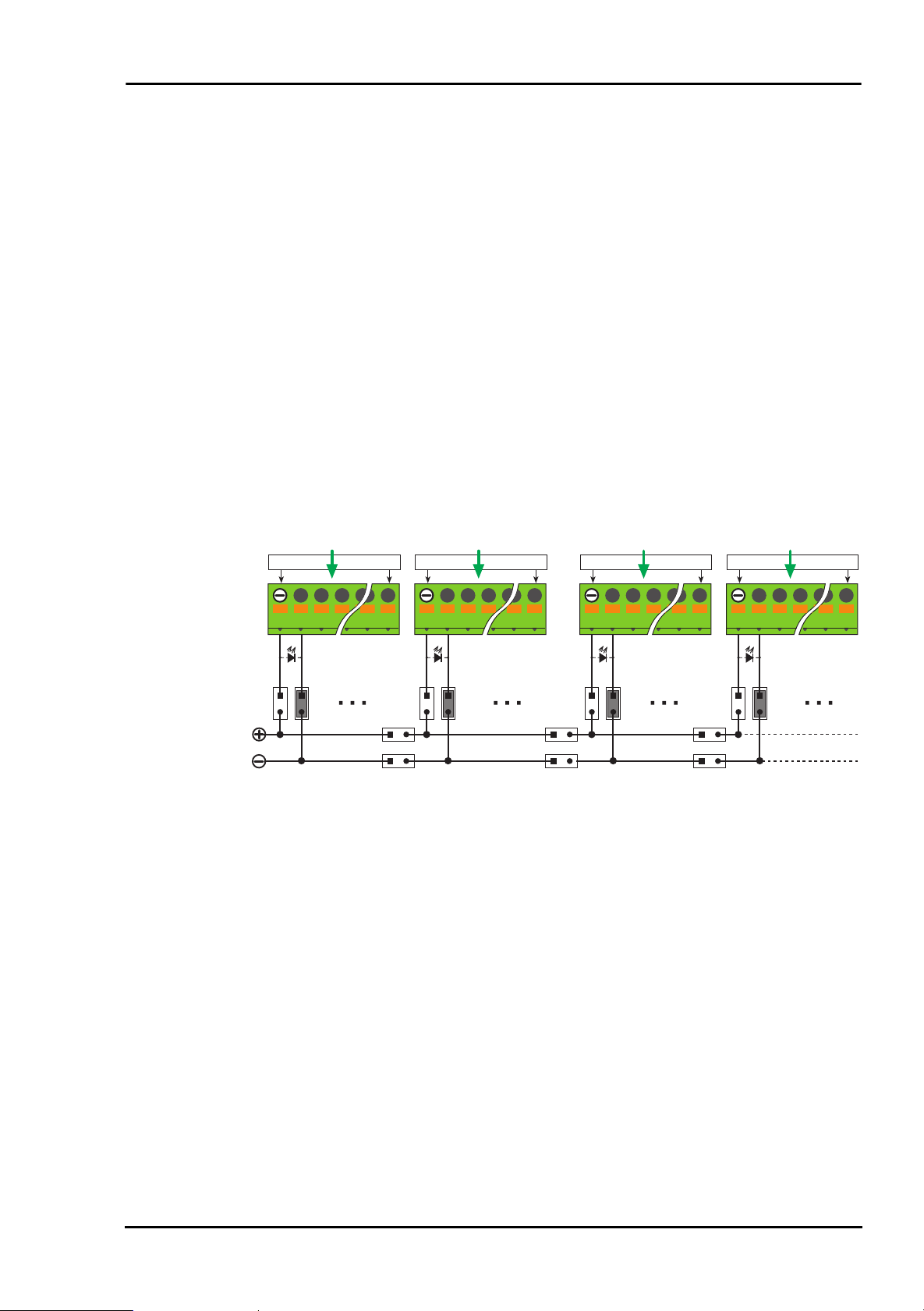
2.6.1 Connection to ME-1000
By a special connection cable of type ME AK-D78/1000 two
ME-63Xtend boards can be connected to a ME-1000/64 directly.
If you are using a ME-1000/128: with one more connection cable
of type ME AK-D78/1000 two additional ME-63Xtend boards can
be connected to the ME-1001.
With up to 4 special connection cables ME AK-D2578/1000 you
can connect one more ME-63Xtend board to the previous
ME-63Xtend board (ST2) in daisy-chain operation. (Note: Only
one additional board can be connected).
With that you can control up to four ME-63Xtend boards
(64 channels) with one ME-1000/64 and up to eight ME-63Xtend
boards (128 channels) with one ME-1000/128. Of course smaller
extension boards are also possible.
Please note, that the digital I/O lines of the ME-1000 are organized in 32 bit wide ports, which can be configured for input or
output by port only. Because of this the ME-634 can not be used
in combination with the ME-1000. ME-X63tend boards used in
daisy chain configuration must be of type input (ME-632) or output (ME-631/633/635).
Hardware Page 30 Meilhaus Electronic
Page 31

Manual ME-63Xtend Series Rev. 1.2E
ME-1000/64
ME-1001 ME-1000/128=
+
2 x ME AK-D78/1000
Port A: 0…31 Port B: 0…31
Port A: 0…15
4 x ME AK-D2578/1000
n.c. n.c. n.c. n.c.
Port A: 16…31 Port B: 16…31 Port C: 16…31 Port D: 16…31
Diagram 17: Connection to ME-1000
Port C: 0…31 Port D: 0…31
Port D: 0…15Port C: 0…15Port B: 0…15
Meilhaus Electronic Page 31 Hardware
Page 32

Rev. 1.2E Manual ME-63Xtend Series
2.6.2 Connection to ME-1400
By a 1:1 connection cable of type ME AK-D78 (or ME-AK-D78/1)
a ME-63Xtend board can be connected to a ME-1400(A/B) directly.
The 8 bit port C as well as the counters 0…2 (not on ME-1400)
are feed-through to the 25pin D-Sub connector (ST2). On demand you can use a connection block (ME AB-D25M) and a
25pin D-Sub cable (ME AK-D25).
Basically the boards of the ME-63Xtend series can also be used
with the ME-1400B. However the digital ports D, E and F as well
as the counters 3…5 are not feed-through to the 25pin D-Sub
connector.
ME-1400(A)
ME AK-D78
ME AK-D25ME AB-D25M
Port C: 0…7;
Clk 0…2;
Gate 0…2;
Out 0…2
Port B:
0…7
Port A:
0…7
Diagram 18: Connection to ME-1400
Hardware Page 32 Meilhaus Electronic
Page 33

Manual ME-63Xtend Series Rev. 1.2E
2.6.3 Connection to ME-Boards with extra port
Connect the boards of the ME-63Xtend series to the bi-directional
TTL ports (ST2) of the ME-630 series, ME-4600 series and
ME-6000 series. The extra mounting bracket ME AK-D25F/S
included with the package must be installed (see manual of the
board). With the special connection cable ME AK-D2578/4000
the ME-63Xtend board is connected to the 25pin D-Sub jack of
the extra mounting bracket (ME-630 USB: direct connection to
the 25pin D-Sub connector of the device).
ME-630
ME AK-D25F/S
ME-4600
ME-6000
Series
ME-630: Port C, D
ME-46x0: Port C, D
ME-6x00: Port A, B
ME AK-D2578/4000
n.c.
Port D:
0…7
Port C:
0…7
Diagram 19: Connection to extra port
Note: To the 25pin D-Sub connector (ST2) of the ME-63Xtend
series no further signals are attached with exeption of VCC and
ground (see diagram 21).
Meilhaus Electronic Page 33 Hardware
Page 34

Rev. 1.2E Manual ME-63Xtend Series
Appendix
A Pinouts
A1 Pinout ST1
➜ ST2*, Pin 22
➜ ST2*, Pin 21
➜ ST2*, Pin 20
➜ ST2*, Pin 19
➜ ST2*, Pin 18
PC-GND
➜ ST2*, Pin 4
➜ ST2*, Pin 3
➜ ST2*, Pin 2
➜ ST2*, Pin 1
Channel 16
Channel 14
Channel 12
Channel 10
PC-GND
Channel 7
Channel 5
Channel 3
Channel 1
PC-GND
➜ ST2*, Pin 9
➜ ST2*, Pin 8
➜ ST2*, Pin 7
➜ ST2*, Pin 6
➜ ST2*, Pin 5
➜ ST2*, Pin 17
➜ ST2*, Pin 16
➜ ST2*, Pin 15
➜ ST2*, Pin 14
PC-GND
Channel 15
Channel 13
Channel 11
Channel 9
Channel 8
Channel 6
Channel 4
Channel 2
VCC (+5V)
20
19
18
17
16
15
14
13
12
11
10
59
39
38
37
36
35
34
33
32
31
30
29
9
28
8
27
7
26
6
25
5
24
4
23
3
22
2
21
1
78
58
77
57
76
56
75
55
74
54
73
53
72
52
71
51
70
50
69
49
68
48
67
47
66
46
65
45
64
44
63
43
62
42
61
41
60
40
PC-GND
VCC (+5V)
n.c.
n.c.
n.c.
n.c.
n.c.
n.c.
n.c.
n.c.
n.c.
PC-GND
n.c.
n.c.
n.c.
n.c.
n.c.
n.c.
n.c.
n.c.
PC-GND
n.c.
n.c.
n.c.
n.c.
n.c.
n.c.
n.c.
n.c.
PC-GND
n.c.
n.c.
n.c.
n.c.
n.c.
n.c.
n.c.
n.c.
VCC (+5V)
Diagram 20: Pinout 78pin D-Sub connector ST1
Please note chapter 2.6 "Connection Options" on page 30!
Pinouts Page 34 Meilhaus Electronic
Page 35

Manual ME-63Xtend Series Rev. 1.2E
A2 Pinout ST2
*Px 16
*P
x
18
*P
x
20
*P
x
22
*P
x
24
*P
x
26
*P
x
28
*P
x
30
n.c.
VCC
VCC
PC-GND
PC-GND
PC0
PC2
PC4
PC6
(Clk 0)
(Out 0)
(Gate 1)
(Clk 2)
(Out 2)
only ME-1400A/B
VCC
VCC
PC-GND
PC-GND
10
11
12
13
1
14
2
15
3
16
4
17
5
18
6
19
7
20
8
21
9
22
23
24
25
PC1
PC3
PC5
PC7
(Gate 0)
(Clk 1)
(Out 1)
(Gate 2)
(OSC/IR IN)
VCC
PC-GND
PC-GND
ME-1400(A/B)
*P
x
17
*P
x
19
*P
x
21
*P
x
23
*P
x
25
*P
x
27
*P
x
29
*P
x
31
n.c.
VCC
PC-GND
PC-GND
ME-1000/1001
Diagram 21: Pinout of the 25pin D-Sub connector ST2
Note for boards of ME-630, ME-4600 and ME-6000 series: To
the 25pin D-Sub connector (ST2) of the ME-63Xtend series no
further signals are attached with exeption of VCC and ground
(see also diagram 19).
*„Daisy-Chain“ operation with the ME-1000:
If you connect a second board of the ME-63Xtend series to the
25pin D-Sub connector ST2 using the special connection cable
ME AK-D2578/1000 the digital I/Os Px16…31 of each port (A, B,
C, D) are attached (see also chapter 2.6 "Connection Options" on
page 30).
Condition is using the special connection cable ME AK-D78/1000
to connect boards of the ME-63Xtend series to the ME-1000/64
(up to 64 channels) resp. ME-1000/128 (up to 128 channels).
Note: ME-1000/64 + ME-1001 = ME-1000/128.
Meilhaus Electronic Page 35 Pinouts
Page 36

Rev. 1.2E Manual ME-63Xtend Series
B Specifications
B1 ME-63Xtend Series (all models)
General Specifications
Physical size 160 x 100 mm
(without mounting kit)
Mounting DIN Rail Mounting Kit included
Connectors 78pin D-Sub female connector (to I/O
board), 25pin D-Sub female connector (for
feed through signals), detachable clam-
ping blocks for inputs and outputs
Operating temperature 0…70 °C
Storage temperature 0…50°C
Relative humidity 20…55% (non condensing)
CE Certification
EMC Directive 89/336/EMC
Emission EN 55022
Noise immunity EN 50082-2
Specifications Page 36 Meilhaus Electronic
Page 37

Manual ME-63Xtend Series Rev. 1.2E
B2 ME-631
Number of relays 16 Form C relays
Relay type Nais APE3014H
Note: The index „out“ refers to the clamps KL1…6; the index „in“ refers to the 78pin D-Sub female
connector.
Maximum Ratings
Conditions: TA=25°C
Measurement Values Test Conditions MIN MAX Unit
Operating voltage U
Input voltage U
Switching voltage U
Switching voltage U
Permanent current I
b
in
out
out
out, max
Switching power non destructive,
non destructive -0,5 +8 V
non destructive -0,5 30 V
non destructive 400 V
non destructive 300 V
non destructive 6 A
1500 VA
AC
DC
cosϕ=1
Isolation voltage
coil/contact U
ISO
Isolation voltage
contact/contact U
Off
4000 V
1000 V
AC,rms
AC,rms
Recommended Operating Conditions
Conditions: Ub=5V±10%, TA=25°C
Measurement Values Test Conditions MIN Typ MAX Unit
U
b
I
U
U
I
out
out
out
= I
out
out, max
I
= I
out
out, max
time unlimited, all
12
12
0,1
channels
1)
on small load the life time of contacts is decreasing.
1)
1)
1)
5V
250 V
30 V
6A
AC
DC
Meilhaus Electronic Page 37 Specifications
Page 38

Rev. 1.2E Manual ME-63Xtend Series
Static Values
Conditions: Ub=5V±10%, TA=25°C
Measurement Values Test Conditions MIN Typ MAX Unit
U
U
I
in,H
in,H
in,L
Uin=3,85V 0,93 1,35 mA
3,5 Ub - 0,6 V
1,5 V
Dynamic Values
Conditions: Ub=5V±10%, TA=25°C
Measurement Values Test Conditions MIN Typ MAX Unit
f
in
t
pd,on
t
pd,off
Contact life time I
without load 20 Hz
58 ms
2,5 4 ms
=6A,
out
U
=250VAC,
out
3 x 10
4
5 x 10
6
cosϕ=1
Specifications Page 38 Meilhaus Electronic
Page 39

Manual ME-63Xtend Series Rev. 1.2E
B3 ME-632
Inputs 16 digital inputs
Opto-isolation up to 2500 VDC
Note: The index „in“ refers to the clamps KL1…4; the index „out“ refers to the 78pin D-Sub female
connector.
Maximum Ratings
Conditions: TA=25°C
Measurement Values Test Conditions MIN MAX Unit
Operating voltage U
Input voltage U
I
out
in
b
non destructive -0,5 +7 V
non destructive -5 70 V
non destructive,
-60 +150 mA
1 channel
U
ISO
f=60Hz, t=1min 2500 V
AC,rms
Recommended Operating Conditions
Conditions: Ub=5V±10%, TA=25°C
Measurement Values Test Conditions MIN Typ MAX Unit
U
I
in
out
t=1s, 1 channel ±60 ±115 ±200 mA
060V
Static Values
Conditions: Ub=5V±10%, TA=25°C
Measurement Values Test Conditions MIN Typ MAX Unit
U
U
U
U
R
I
in
in,H
in,L
out,H
out,L
in
I
=-24mA,
out
=4,5V
U
b
I
=24mA,
out
U
=4,5V
b
Uin=24V 4,3 kΩ
Uin = 60V 6,5 10 mA
2,30 60 V
0 2,20 V
2,4 3,3 V
0,3 0,55 V
Meilhaus Electronic Page 39 Specifications
Page 40

Rev. 1.2E Manual ME-63Xtend Series
Dynamic Values
Conditions: Ub=5V±10%, TA=25°C
Measurement Values Test Conditions MIN Typ MAX Unit
f
in
f
in
f
in
t
pd,HL
t
pd,LH
Output switching, duty
cycle 12%, U
=10V
in
Output switching, duty
cycle 50%, U
=10V
in
Output switching, duty
cycle 50%, U
=2,35V
in
fin=1kHz, Uin=10V 36 µs
fin=1kHz, Uin=10V 1,9 µs
23 kHz
10,5 kHz
62 kHz
Input current related to Maximum input frequency related to
input voltage input voltage
TA=25°C, Ub=5,0V, f=0Hz TA=25°C, Ub=5,0V, output switching
I [mA]
7
6
5
4
3
2
1
0
0 1020 30 4050 60
U [V]
f [kHz]
65
60
55
50
45
40
35
30
25
20
15
10
2 4 6 8 101214161820
U [V]
Specifications Page 40 Meilhaus Electronic
Page 41

Manual ME-63Xtend Series Rev. 1.2E
B4 ME-633
Outputs 16 digital outputs
Opto-isolation up to 2500 VDC
Note: The index „out“ refers to the clamps KL1…4; the index „in“ refers to the 78pin D-Sub female
connector.
Maximum Ratings
Conditions: TA=25°C
Measurement Values Test Conditions MIN MAX Unit
Operating voltage U
Input voltage U
U
out
I
out
in
b
non destructive -0,5 +7 V
non destructive -0,5 Ub + 0,5 V
non destructive -0,8 70 V
non destructive,
-200 1000 mA
t=10s
U
ISO
f=60Hz, t=1min 2500 V
AC,rms
Recommended Operating Conditions
Conditions: Ub=5V±10%, TA=25°C
Measurement Values Test Conditions MIN Typ MAX Unit
U
I
out
out
I
> 100µA 0,6 60 V
out, on
time limited, all
0 300 mA
channels
I
out, peak
t=1min, 1 channel 400 mA
Static Values
Conditions: Ub=5V±10%, TA=25°C
Measurement Values Test Conditions MIN Typ MAX Unit
U
in,H
U
in,L
U
out,on
U
out,on
R
on
R
off
I
=100mA 0,86 V
out
I
= I
out
out, max
U
= U
out
out, max
2V
0,8 V
1,00 1,03 1,2 V
3 10 700 mΩ
600 MΩ
Meilhaus Electronic Page 41 Specifications
Page 42

Rev. 1.2E Manual ME-63Xtend Series
Dynamic Values
Conditions: Ub=5V±10%, TA=25°C
Measurement Values Test Conditions MIN Typ MAX Unit
f
in
t
pd,HL
t
pd,LH
t
tr,HL
t
tr,LH
U
=90%,
out
=100mA
I
out
I
=100mA,
out
=1kHz
f
out
I
=100mA,
out
=1kHz
f
out
I
=100mA,
out
f
=1kHz
out
I
=100mA,
out
f
=1kHz
out
5,0 5,5 5,7 kHz
90 µs
2,2 µs
1,4 µs
62 µs
Forward voltage related to load current Maximum input frequency related to
TA=25°C, Ub=5,0V, f=0Hz load current, TA=25°C, Ub=4,5V, ∆U=1%
U [V]
3,5
3,0
2,5
2,0
1,5
1,0
0,5
f [kHz]
8
7
6
5
4
3
2
1
0,0
0
50
100
150
200
250
300
350
400
450
I [mA]
500
0
0
50
100
150
200
250
300
350
400
450
500
I [mA]
Specifications Page 42 Meilhaus Electronic
Page 43

Manual ME-63Xtend Series Rev. 1.2E
B5 ME-634
Inputs 8 digital inputs
Outputs 8 digital outputs
Opto-isolation up to 2500 VDC
- Specifications of the input channels see ME-632 on page 39.
- Specifications of the output channels siehe ME-633 on page 41.
B6 ME-635
Anzahl Relais 16 Halbleiter-Relais
Note: The index „out“ refers to the clamps KL1…4; the index „in“ refers to the 78pin D-Sub female
connector.
Maximum Ratings
Conditions: TA=25°C
Measurement Values Test Conditions MIN MAX Unit
Operating voltage U
Input voltage U
in
Switching voltage U
Switching voltage U
Permanent current I
Peak current I
out
Isolation voltage
input/output U
ISO
b
out
out,max
out
non destructive -0,5 +8 V
non destructive -0,5 30 V
non destructive 280 V
transient 600 V
non destructive 6 A
t=15ms 250 A
f=50/60Hz 4000 V
AC,rms
pp
AC,rms
Meilhaus Electronic Page 43 Specifications
Page 44

Rev. 1.2E Manual ME-63Xtend Series
Recommended Operating Conditions
Conditions: Ub=5V±10%, TA=25°C
Measurement Values Test Conditions MIN Typ MAX Unit
Operating voltage U
Output voltage U
Output current I
out
out
b
time unlimited, all channels
12 280 V
60 4000 mA
5V
(without forced ventilation)
Output current I
out
time unlimited, maximum
60 5000 mA
each second channel in operation, (without forced
ventilation)
Static Values
Conditions: Ub=5V±10%, TA=25°C
Measurement Values Test Conditions MIN Typ MAX Unit
U
in,H
U
in,L
I
in,H
Voltage drop at output U
Uin=3,85V 0,93 1,35 mA
out=Uout,max
3,5 Ub + 0,6 V
1,5 V
1,4 V
AC,rms
AC,rms
AC,rms
AC
Dynamic Values
Conditions: Ub=5V±10%, TA=25°C
Measurement Values Test Conditions MIN Typ MAX Unit
f
in
t
pd,on
t
pd,off
cosϕ Maximum load 0,5 1
1 VAC cycle
0,5 VAC cycle
0,5 VAC cycle
Specifications Page 44 Meilhaus Electronic
Page 45

Manual ME-63Xtend Series Rev. 1.2E
C Accessories
The following products are available as an option (see also
chapter 2.6 "Connection Options" on page 30):
ME AK-D78(/1)
78pin D-Sub cable (male - female), 2 m (1 m), for connection of
a board of the ME-63Xtend series to the ME-1400(A/B).
ME AK-D25
25pin D-Sub connection cable (male - female), 2 m, for connection of a connector block ME AB-D25M to ST2 of the ME-63Xtend
series.
ME AB-D25M
25pin connector block with clamping blocks.
ME AK-D78/1000
Special connection cable from 78pin D-Sub male connector to
2 x 78pin D-Sub female connector for connection of 2 boards of
the ME-63Xtend series to a ME-1000 resp. ME-1001.
ME AK-D2578/1000
Special connection cable from 25pin D-Sub male connector to
78pin D-Sub female connector. Required for daisy chain operation of 2 boards of the ME-63Xtend series in combination with a
ME-1000 resp. ME-1001.
ME AK-D2578/4000
Special connection cable from 25pin D-Sub male connector to a
78pin D-Sub female connector to connect the ME-63Xtend series
with a board of the series ME-630 (incl. MEphisto Switch),
ME-4600 and ME-6000.
Meilhaus Electronic Page 45 Accessories
Page 46

Rev. 1.2E Manual ME-63Xtend Series
D Technical Questions
D1 Fax-Hotline
If you should have any technical questions or problems with the
board, please send a detailed description of the problem to our
hotline:
Fax-Hotline: (+49) (0)89 - 89 01 66-28
eMail: support@meilhaus.de
D2 Service address
We hope that your board will never need to be repaired. If this
should become necessary please contact us at the following
address:
Meilhaus Electronic GmbH
Service Department
Fischerstraße 2
D-82178 Puchheim/Germany
If you would like to send your board to Meilhaus Electronic for
repair, please do not forget to add a detailed description of the
problem
Technical Questions Page 46 Meilhaus Electronic
Page 47

Manual ME-63Xtend Series Rev. 1.2E
E Index
A
Accessories 45
C
Connection Options 30
ME-1000 30
ME-1400 32
ME-4600 33
ME-6000 series 33
ME-630 series 33
Connectors 34
F
Fax hotline 46
I
Pinout 16
Specifications 39
ME-633
Block diagram 18
Control 17
Jumper settings 19
Pinout 21
Pullup resistors 20
Specifications 41
ME-634
Block diagram 23
Control 22
Introduction 5
M
ME-631
Block diagram 10
Control 9
Pinout 12
Protection Circuit 10
Specifications 37
ME-632
Block diagram 14
Control 13
Jumper settings 15
Jumper settings 24
Pinout 26
Pullup resistors 25
Specifications 43
ME-635
Block diagram 28
Control 27
Pinout 29
Specifications 43
Model Overview 7
P
Package contents 5
Pinout 34
Meilhaus Electronic Page 47 Index
Page 48

Rev. 1.2E Manual ME-63Xtend Series
S
Service address 46
Specifications 36
T
Technical questions 46
W
Warning 5
Index Page 48 Meilhaus Electronic
 Loading...