

Page 1
Meilhaus Electronic Manual
ME-630
(PCI, PCI-Express, CompactPCI)
8/16 Relays, 16 TTL I/Os, TTL Inputs and/or
Opto-Isolated Inputs
Page 2

Imprint
Manual ME-630
Revision 3.0E
Revised: 2019-11-27
Meilhaus Electronic GmbH
Am Sonnenlicht 2
D-82239 Alling bei München
Germany
www.meilhaus.de
© Copyright 2019 Meilhaus Electronic GmbH
All rights reserved. No part of this publication may be reproduced
or distributed in any form whether photocopied, printed, put on
microfilm or be stored in any electronic media without the
expressed written consent of Meilhaus Electronic GmbH.
Important note:
The information contained in this manual has been reviewed with
great care and is believed to be complete and accurate. Meilhaus
Electronic assumes no responsibility for its use, any infringements
of patents or other rights of third parties which may result from
use of this manual or the product. Meilhaus Electronic assumes no
responsibility for any problems or damage which may result from
errors or omissions. Specifications and instructions are subject to
change without notice.
Note the Meilhaus Electronic general terms of business:
www.meilhaus.de/en/infos/my-shop/tob/
All trademarks acknowledged. All trademarks are property of their
respective owners.
Page 3
Content
1 Introduction ........................................................... 5
1.1 Important Notes ............................................................... 5
1.1.1 Use in Accordance with the Requirements ....................... 5
1.1.2 Improper Application ...................................................... 6
1.1.3 Unforseeable Misapplications .......................................... 6
1.2 Package Contents ............................................................. 7
1.3 Features .......................................................................... 7
1.4 System Requirements ....................................................... 8
1.5 Software Support ............................................................. 8
2 Starting up ............................................................ 9
2.1 Software Installation ......................................................... 9
2.2 Power Supply for PCI-Express Models.................................. 9
2.3 Test Program .................................................................. 10
3 Hardware ............................................................ 11
3.1 Block Diagrams ............................................................... 11
3.2 General Notes ................................................................. 14
3.3 Relays ............................................................................ 15
3.4 Digital-I/O Section ........................................................... 18
3.4.1 TTL Inputs ................................................................... 18
3.4.2 Opto-Isolated Inputs .................................................... 19
3.4.3 Bidirectional TTL Ports ................................................. 20
3.5 Interrupt Inputs .............................................................. 21
4 Programming ....................................................... 22
4.1 Relays ............................................................................ 22
4.2 Digital-I/O Section ........................................................... 23
4.3 External Interrupt ........................................................... 24
5 Appendix ............................................................. 25
A Specification .......................................................................... 25
B Pinout ................................................................................... 28
B1 78-pin D-Sub (ST1) – ME-630 “Standard” PCI, cPCI .......... 29
Page 4

B2 78-pin D-Sub (ST1) – ME-630 “Standard” PCIe .................. 30
B3 78-pin D-Sub (ST1) – ME-630/x-0 ..................................... 31
B4 Auxiliary Connector (ST2) ................................................. 32
C Accessories ........................................................................... 33
D Technical Questions ................................................................ 34
D1 Hotline ........................................................................... 34
E Index ..................................................................................... 35
Page 5

1 Introduction
Valued customer,
Thank you for purchasing this device from Meilhaus Electronic. You
have chosen an innovative high-technology product that left our
premises in a fully functional and new condition.
Please take the time to carefully examine the contents of the
package for any loss or damage that may have occurred during
shipping. If there are any items missing or if an item is damaged,
please contact us immediately.
Before installing the board in your computer, we recommend you
read this manual carefully, especially the chapter describing board
installation.
The descriptions in this manual concern PCI-, PCI-Express- and
CompactPCI-versions of the ME-630 series if not otherwise noted.
1.1 Important Notes
1.1.1 Use in Accordance with the Requirements
The PC boards of the ME-series are designed for acquisition and
output of analog and digital signals with a PC. Depending on type
install the models of the ME-series into:
a free PCI slot (PCI versions) or
a free PCI Express slot (PCIe versions) or
a free CompactPCI-slot (3 HE cPCI versions)
For information on how to install a plug-in board please read the
manual of your PC.
Please note the instructions and specifications as presented in
this manual (Appendix A, Specifications):
Please ensure sufficient heat dissipation for the board within
the PC housing.
All unused inputs should be connected to the ground reference
of the appropriate functional section. This avoids cross talk
between the input lines.
Page 6

The opto-isolated inputs and outputs achieve an electrical
isolation of the application relative to PC ground.
Note that the computer must be powered up prior to
connecting signals by the external wiring of the board.
As a basic principle, all connections to the board should only be
made or removed in a powered-down state of all components.
Ensure that no static discharge occurs while handling the
board or while connecting/disconnecting the external cable.
Ensure that the connection cable is properly connected. It
must be seated firmly on the D-Sub connector and must be
tightened with both screws, otherwise proper operation of the
board cannot be guaranteed.
1.1.2 Improper Application
PC plug-in boards for the PCI-, PCI-Express- or CompactPCI-bus
may not be taken into operation outside of the PC. Never connect
the devices with voltage-carrying parts, especially not with mains
voltage.
Make sure that no contact with voltage-carrying parts can happen
by the external wiring of the device. As a basic principle, all
connections should only be made or removed in a powered-down
state.
1.1.3 Unforeseeable Misapplications
The device is not suitable to be used as a children’s toy, in the
household or under unfavourable environmental conditions (e.g. in
the open). Appropriate precautions to avoid any unforeseeable
misapplication must be taken by the user.
Page 7
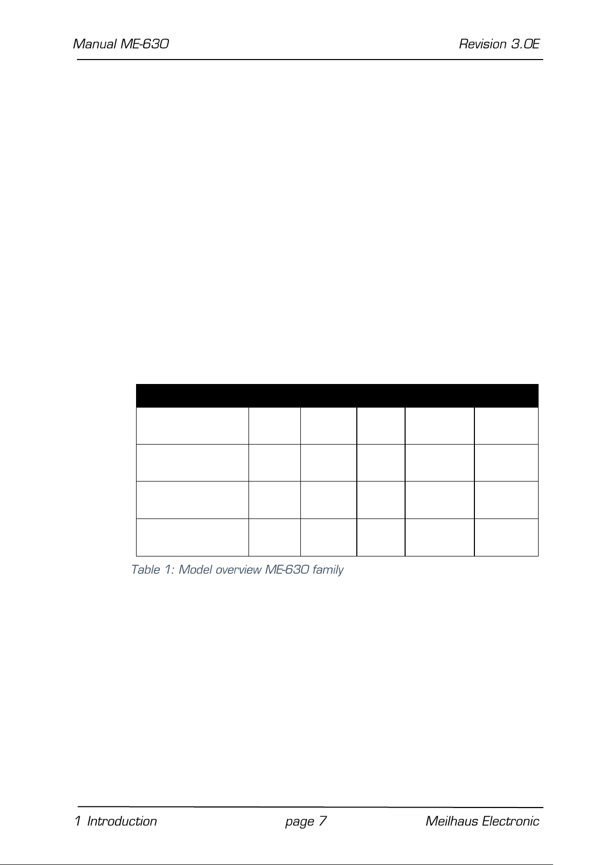
Model
Relays
Opto-In
TTL-In
TTL-I/Os*
IRQ
ME-630/16
PCI/PCIe/cPCI
16 8 8
16
2 (TTL)
ME-630/8
PCI/PCIe/cPCI
8 8 8
16
2 (TTL)
ME-630/16-O
PCI/PCIe/cPCI
16
16 – 16
2
(isolated)
ME-630/8-O
PCI/PCIe/cPCI
8
16 – 16
2
(isolated)
1.2 Package Contents
We take great care to ensure your delivery is complete.
Nonetheless, please check the list enclosed to verify the contents
of your delivery. You should find included:
Relay board for PCI, PCI-Express or CompactPCI
Manual in PDF format on CD/DVD
Driver software on CD/DV
78-pin D-Sub male connector
Additional mounting bracket (PCI-, PCI-Express- and Compact-
PCI-versions)
25-pin D-Sub male connector
1.3 Features
Model overview:
The ME-630 series are universal relay boards designed for PCI-,
PCI-Express- resp. CompactPCI-bus.
Common features to all models:
8 resp. 16 changeover relays (Form C), switching loads up to
30 V/2 A (DC/AC),
8 opto-isolated inputs working with 24 V input level.
Additionally, the standard models (without „-O“ in the model name)
provide…
8 TTL-inputs and 2 TTL-interrupt-inputs …
Page 8
instead of the „O“ versions provide:
8 opto-isolated inputs and 2 opto-isolated interrupt inputs
working with 24 V input level.
PCI-Express models as well as PCI and cPCI with hardware revision
3.0 and higher:
16 additional TTL-I/Os. These are organized as 2 bi-directional,
8-bit-wide TTL-ports. Connection is done by the 25-pin D-Sub
connector ST2. Therefore an extra mounting bracket is included
with the package of PCI-, PCIe- and CompactPCI-versions.
1.4 System Requirements
The ME-series may be installed into any PC (Intel® Pentium®
processor) with a free standard PCI-, PCI-Express- resp.
CompactPCI-slot (32 bit, 33 MHz, 5 V). The board is supported by
the Meilhaus Electronic Intelligent Driver System (ME-iDS).
1.5 Software Support
The ME-series is supported by the Meilhaus Electronic Intelligent
Driver System (ME-iDS). The ME-iDS is a unique driver system
covering different devices and operating systems. It supports
Windows 2000/XP/Vista and Windows 7, 8.1, 10 and contains a
universal function library (API) for all common programming
languages.
A detailed description of the functions can be found in the ME-iDS
manual on the CD/DVD enclosed.
Please also note the corresponding README-files.
Page 9
2 Starting up
Please read your computer’s instruction manual on how to install
new hardware components before installing the board.
2.1 Software Installation
Installation under Windows
The following basic procedure should be used:
If you have received the driver software as an archive file please unpack the software before installing the board. First choose a
directory on your computer (e.g. C:\Temp\Meilhaus\ME-iDS).
Use the Meilhaus Electronic Intelligent Driver System (ME-iDS) for
programming your new data acquisition hardware. For installation
and operation of the driver system, please follow the
documentation in electronic form included with the software
package.
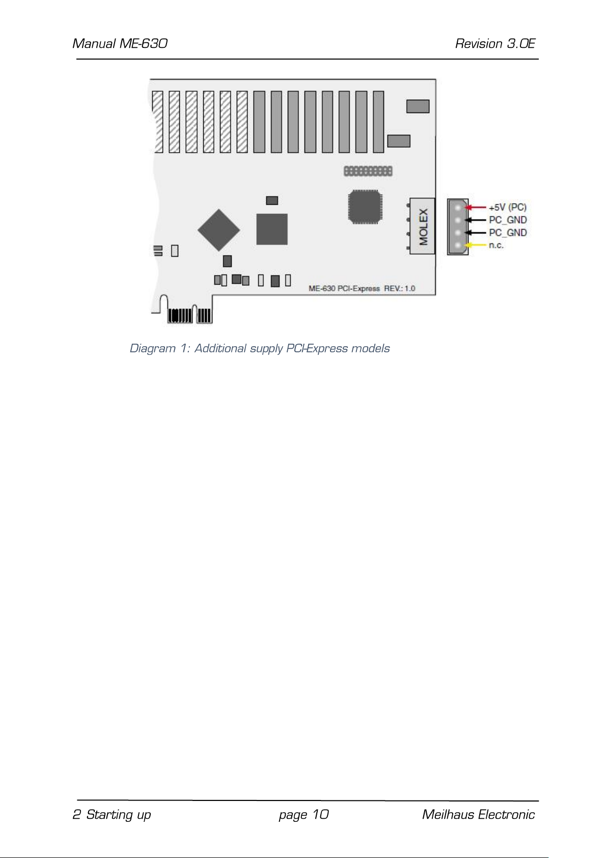
2.2 Power Supply for PCI-Express Models
Because of the PCI-Express slot drive’s insufficient current for
operation of the board, an additional supply is required via the PC
power supply. For that purpose connect a free „MOLEX“-connector
of the PC (also as used for power supply of drives) with the
appropriate terminal of the board (see the following diagram).
Page 10
2.3 Test Program
For simple testing of the board use the corresponding test
program provided with the ME-iDS.
Page 11
3 Hardware
3.1 Block Diagrams
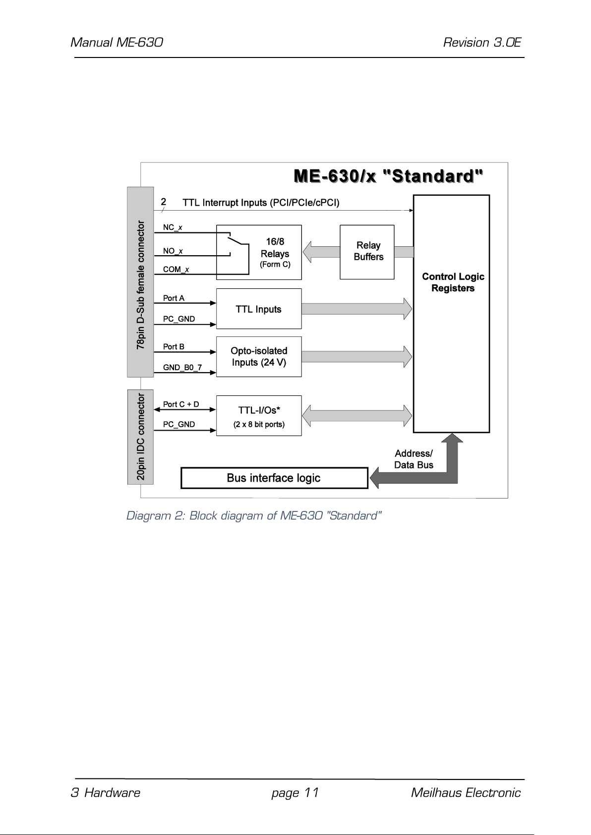
ME-630/16 PCI/PCIe/cPCI: 16 relays (type C), 2 IRQ-inputs
ME-630/8 PCI/PCIe/cPCI: 8 relays (type C), 2 IRQ-inputs
All boards… provide 8 TTL-inputs, 8 opto-isolated inputs,
16 bidirectional TTL-I/Os*
*TTL-I/OS on all PCI-Express as well as PCI- and cPCI-models with hardware
revision 3.0 and higher.
Page 12

ME-630/16-O PCI/PCIe/cPCI: 16 relays (type C),
2 opto-isolated IRQ-inputs
ME-630/8-O PCI/PCIe/cPCI: 8 relays (type C),
2 opto-isolatedIRQ inputs
All boards… provide 16 opto-isolated inputs and 16 bidirectional
TTL-I/Os
Page 13

Page 14

3.2 General Notes
Important Note: The external connections to the board should only
be made or removed in a powered-down state.
Before handling and installing the board and cable, make sure that
you ground yourself. Electrostatic discharge can damage some of
the more sensitive components on the board.
Look for proper connection of the cable. It must join the Sub-D jack
completely and must be fixed with both screws. Otherwise a
proper operation of the board cannot be guaranteed!
All unused input channels should be grounded to avoid crosstalk
between the input lines.
For the pin configuration of the 78-pin female D-Sub see „78-pin DSub (ST1) – ME-630 „Standard“ on page 29).
In the following chapters you find a description for wiring of each
functional group. For details of operation modes and programming,
please read chapter 4 on page 22 and following.
Page 15

3.3 Relays
The real current carrying rating of the ME-630 depends on several
conditions, which are described in the following.
Important Notes:
Choose sufficient wire gauges for your external wiring (e.g.
0.5 mm2 at 2 A). Note the resulting power dissipation and provide
a sufficient ventilation of the housing. We strongly advise you to
stick to the following maximum values for the carrying rating of the
ME-630:
When using the connector cable ME-AK-D78(/1): max. 0.5 A
per relay
When using an external wiring with sufficient dimensioning:
- Permanent load at 25 °C environmental temperature: max.
2°A per relay
- Short-term load: max. 3.5 A of single relays
The total power dissipation PG of all relay channels of the board
must not exceed 12.8 W!
The resistance Rn of the board per channel (connector, track, relay
contact) is typ. 200 mΩ (max. 250 mΩ). Use the following formula
for the power dissipation per channel Pn at In = 2 A (with n =
1…16):
Pn = I
2
· Rn = 22 A · 0.2 Ω = 0.8 W
n
i.e. the total power dissipation is:
PG = P
+ … + P
n=1
≤ 12.8 W
n=16
Page 16

Apart from the permanent load, induced voltages and high
transient currents during switching the relays can occur.
Therefore the use of a protection circuit for the contacts is
urgently needed. To guarantee the efficiency of the protection
circuit the distance should not exceed more than 20 cm from the
contact.
The following diagram shows a typical circuitry that could be used.
The values of the components used depend on the load and the
relay properties. The condensator C
when contact opens and the resistor R
suppresses the discharge
NC/NO
limits the current when
NC/NO
switching the next time. The circuitry can be used for DC and AC
operation. The ME-630 offers a normally open contact as well as a
normally closed contact. Therefore the protection circuit must be
provided for every contact switching a considerable load.
Page 17

As a rule for selection of R
R
C
: 0.5…1 Ω per 1 V of switching voltage U
NC/NO
: 0.5…1 µF per 1 A of switching current I
NC/NO
Note: If the computer is powered down and after power-up the
common contacts (COM_x) are connected with the normally closed
contacts (NC_x).
NC/NO
and C
NC/NO
use:
Page 18

3.4 Digital-I/O Section
3.4.1 TTL-Inputs
The standard models of the ME-630 series provide 8 TTL-inputs
(port A). Make sure that the signals are within the TTL-signal-levelspecifications (Low: 0 V…+0,8 V; High: +2,0 V…+5,5 V) and that
a connection to PC ground (Pin 1) exists.
Page 19

Port A
GND-pin
Port B
GND-pin
DI_A0…3
Pin 6 (GND_A0_3)
DI_B0…3
Pin 21 (GND_B0_3)
DI_A4…7
Pin 1 (GND_A4_7)
DI_B4…7
Pin 1 (GND_B4_7)
3.4.2 Opto-Isolated Inputs
The standard models of the ME-630 series provide 8 opto-isolated
inputs (port B) and the models with option „-O“ provide 16 optoisolated inputs (port A and B). The opto-isolated inputs are
designed for 24 V level, which
is common in industrial environment (Low: 0 V…+12 V; High:
+13 V…+24 V). Make sure that a ground reference to the
external wiring is done by the various GND pins of the D-Sub
connector ST1. On the standard models these are the pins 21 and
40. Note on the models with „-O“ option, that for the higher and
lower significant half-byte separate grounds are used. Depending
on the wiring you must connect the pins 1, 6, 21 and 40
separately (see also table 2 and the pinout on page 19). If the
inputs are open a logical „0“ is returned (see diagram).
Page 20

3.4.3 Bidirectional TTL-Ports
All PCI-Express models as well as PCI and cPCI models with
hardware revision 3.0 and higher provide two TTL-ports with 8 bits
each. Each port can be configured independently as input or
output. After power up, all ports are set to input. For more
information about programming refer to chapter 4.2 "Digital-I/O
Section" on page 23.
Both ports C and D are available by the 25-pin D-sub female
connector ST2. With the PCI-, PCI-Express- and CompactPCImodels the additional mounting bracket ME-AK-D25F/S is required
(see pinout on page 28).
It is important that the voltage levels of the digital input/output
wiring is within the TTL-level-limits (see specifications on page 25)
and that a reference to PC ground (PC_GND) is made.
The maximum output current is I
= IOL = IOH = 10 mA.
Out
Page 21

3.5 Interrupt Inputs
The PCI-, PCI-Express- and CompactPCI-models of the ME-630
series offer 2 independent external interrupt inputs.
On standard models the inputs are of TTL-type (Low: 0 V…+0.8 V;
High: +2.0 V…+5.5 V), which require a reference to PC ground
(PC_GND) and are assembled with pull-up resistors on the board.
On models with option „-O“ the IRQ inputs are opto-isolated and
designed for 24 V level (Low: 0 V…+12 V; High: +13 V…+24 V).
The ground reference must refer to pin 45 (GND_IRQ).
As soon as a positive edge occurs an interrupt is initiated
(condition: interrupt enabled by software). The interrupt sources
are processed sequentially.
Page 22

ME-630/x „Standard“
ME-630/x-O
PCI, PCIe, cPCI
PCI, PCIe, cPCI
4 Programming
For programming the device please use the Meilhaus Electronic
Intelligent Driver System (ME-iDS) included in your package. The
ME-iDS is a unique driver system covering different devices and
operating systems. It supports Windows 2000 and higher and
contains a universal function library (API) for all common
programming languages (the extent of the current software
support can be found in the README-files of the ME-iDS).
A detailed description of the functions can be found in the ME-iDS
manual (see CD/DVD enclosed or online:
www.meilhaus.de/download/ME-iDS.
Further details regarding the assignment of the subdevices and
device specific arguments can be found in the help file (help file
format under Windows, *.chm) which can be accessed via the „MEiDS Control Center“ in the info area of the task bar (as a rule in
the lower right corner of the screen) or via the Windows start
menu.
If you do not want to program your board with the ME-iDS but with
the legacy driver you can find the last revision of the old function
reference in the ME-630 manual Rev. 2.3 (see:
www.meilhaus.com/download/ME-630). Please note that we cannot
support this driver anymore.
4.1 Relays
Depending on the model, the ME-630 provides 8 or 16 relays of
type C. Excitation is done in operation mode „Single“. The relays
are accessed as a subdevice of type ME_TYPE_DO, subtype ME_
SUBTYPE_SINGLE. Note the order of operation as described in the
ME-iDS manual. The following parameters can be configured by the
functions and :
Determine subdevice with meQuery…functions
Choose the option ME_SINGLE_CONFIG_DIO_OUTPUT in para-
meter <SingleConfig> of the function .0.
Page 23

ME-630/x „Standard“
ME-630/x-O
PCI, PCIe, cPCI
PCI, PCIe, cPCI
The relays can be accessed separately or all in common (see
parameter iFlags).
If the computer is powered down and after power-up the common
contacts (COM_x) are connected with the normally closed contacts
(NC_x).
Note: The relay control registers can also be read! But you can
also check the actual switching status by the opto-isolated inputs
of the ME-630.
For wiring the relays refer to chapter 3.3 on page 15.
4.2 Digital-I/O Section
Each of the four digital ports of the ME-630 series is considered
as an independent subdevice. Port A and B are always input ports
whereas the TTL-ports C and D are bi-directional. The assignment
of the ports to the subdevices can be found in the ME-iDS help file
(see ME-iDS Control Center).
The input/output of single digital values is done in operation mode
„Single“. Each digital port is accessed as a subdevice of type
ME_TYPE_DI (Port A, B) resp. ME_TYPE_DIO (Port C, D), subtype
ME_SUBTYPE_SINGLE. Note the order of operation as described in
the ME-iDS manual. The following parameters can be configured by
the functions and :
Determine subdevice with … functions.
Port direction: input or output, if not fixed by opto-isolation.
Port width: bit or byte operation (8 bit).
Note: Ports defined as output can also be read back!
For wiring the digital ports please read chapter 3.4 on page 18.
Page 24

ME-630/x „Standard“
ME-630/x-O
PCI, PCIe, cPCI
PCI, PCIe, cPCI
4.3 External Interrupt
At both external interrupt inputs (IRQ_1, pin 64 and IRQ_2, pin 65)
you can initiate an interrupt by a rising edge, which is sent to the
PCI-bus directly.
Programming is done by the … functions. Each of both
interrupt channels is considered to be an independent subdevice of
type ME_TYPE_EXT_IRQ (IRQ_1: subdevice 5, IRQ_2: subdevice 6).
After enabling the external interrupt by the function
an interrupt can be triggered by a rising edge. Note the order of
operation as described in the ME-iDS manual.
For wiring the interrupt channels please read chapter 3.5 on page
21.
Page 25

PC Interface
Bus system
PCI-Bus (32 bit, 33 MHz)
(depends on model)
CompactPCI bus (32 bit, 33 MHz)
PCI-Express x1, Specification Rev. 2.0
Plug&Play operation
fully supported
Relays
Number
8 resp. 16 form C relays
Relay type
NAIS APE3005 or compatible compliant
with EN 60255, EN 60335, EN 60730,
EN 60950, EN 60065, EN 50178
Permanent load
DC: max. 30 VDC/2 A;
AC: max. 30 VAC/2 A
Peak load
short time up to 30 V/3.5 A
(see also chapter “3.3 Relays”)
Resistance per relay channel
type
typ. 200 mΩ; max. 250 mΩ
Isolation resistance
min. 103 MΩ at 500 VDC
Breakdown voltage
contact to contact: 1.000 V
contact to coil: 4.000 V
Operating time
ca. 5 ms (depends on contact rating)
Release time
ca. 3 ms (depends on contact rating)
Switching cycles
> 5 x 10⁶
Monitoring
Relay registers can be read back by
software.
Digital Inputs (TTL)
Number
8 (only ME-630 „Standard“)
Input level (TTL)
low: 0 V…+ 0.8 V (I
IL max.
= ±10 µA)
high: + 2.0 V…+5.5 V (I
IH max.
= ±10 µA)
Reference to ground
PC ground (PC_GND)
5 Appendix
A Specification
Page 26

Digital Inputs (opto-isolated)
Number
ME-630 “Standard”: 8
ME-630 “-0”: 16
Input level
low: 0 V…+ 12 V
high: + 13 V…+ 24 V
Input current
typ. 7.5 mA at 24 V
Isolation voltage
500 VDC
Signal frequency
max. 1 kHz
Reference to ground
ground of the appropriate channel group
(GND…)
Bidirectional Digital I/Os(TTL)
Ports
2 x 8 bit
Reference to ground
PC ground (PC_GND)
Port type
bidirectional TTL ports
Output level
UOL
max.0.5 V at 24 mA
UOH
min. 2.4 V at -24 mA
Input level
UIL
max. 0.8 V at Vcc = 5 V
UIH
min. 2 V at Vcc = 5 V
Input current
±1 µA
Interrupt Channels (PCI-/PCIe-/cPCI-models)
Number
2
Input level
ME-630/x „Standard“: see TTL inputs
ME-630/x-O: see opto-isolated inputs
Reference to ground
ME-630/x „Standard“: PC_GND
ME-630/x-O: GND_IRQ
General Information (PCI/PCIe/cPCI models)
Power consumption at +5 V
typ. 850 mA (16 relays)
Physical size (without mounting bracket and connector)
ME-630 PCI: 174 mm x 98 mm
Page 27

ME-630 PCIe: 167.65 mm x 111.15 mm
ME-630 cPCI: 3U CompactPCI board
Connectors
78-pin D-Sub female connector ST1;
25-pin D-Sub female connector ST2
(by extra mounting bracket)
Common Specifications
Operating temperature
0…70 °C
Storage temperature
-40…100 °C
Relative humidity
20…55 % (non-condensing)
Certification
CE
Page 28

NC_
break contact relay (normally closed)
NO_
make contact relay (normally open)
COM_
common relay contact (COMmon)
DI_A
digital input port A (ME-630 „Standard“: TTL,
ME-630 „-O“: opto-isolated)
DI_B
digital input port B (opto-isolated)
DIO_C
bidirectional TTL port C
DIO_D
bidirectional TTL port D
IRQ_1
interrupt channel 1 (TTL resp. opto-isolated)
IRQ_2
interrupt channel 2 (TTL resp. opto-isolated)
GND_A0_3
ME-630 „-O“: reference to ground for
opto-isolated inputs DI_A0…3
GND_A4_7
ME-630 „-O“: reference to ground for
opto-isolated inputs DI_A4…7
GND_B0_3
ME-630 „-O“: reference to ground for
opto-isolated inputs DI_B0…3
GND_B4_7
ME-630 „-O“: reference to ground for
opto-isolated inputs DI_B4…7
GND_B0_7
ME-630 „Standard“: reference to ground for
opto-isolated inputs DI_B0…7
GND_IRQ
ME-630 „-O“: reference to ground for
opto-isolated interrupt inputs IRQ_
PC_GND
PC ground
VCC_OUT
VCC output (PCI, cPCI: +5 V, PCI-Express: +3.3 V)
max. 200 mA load
n.c.
pin not connected
B Pinout
Page 29

B1 78-pin D-Sub (ST1) – ME-630 “Standard” PCI, cPCI
*The pins of the relays 8…15 are not connected on the ME-630/8.
Signals shaded with the same color use a common reference to
ground.
Page 30

B2 78-pin D-Sub (ST1) – ME-630 “Standard” PCIe
*The pins of the relays 8…15 are not connected on the ME-630/8.
Signals shaded with the same color use a common reference to
ground.
Page 31

B3 78-pin D-Sub (ST1) – ME-630/x-0
*The pins of the relays 8…15 are not connected on the ME-630/8.
Signals shaded with the same color use a common reference to
ground.
Page 32

B4 Auxiliary Connector (ST2)
Note: For the PCI-, PCIe- and CompactPCI-models an extra
mounting bracket with an adapter cable from 20-pin IDC-connector
to 25-pin D-Sub female connector is required (comes with the
board).
Attention: When connecting the mounting bracket make sure to
plug in pin 1 of the flat ribbon cable (red marked line) as shown
above to the IDC connector ST2.
Page 33

C Accessories
We recommend to use high-quality connector cables with singleshielded lines per channel.
For further accessories please refer to the current Meilhaus
Electronic catalog and the internet:
www.meilhaus.de/en/pc-boards/accessories/
Page 34

D Technical Questions
D1 Hotline
Should you have questions or inquiries concerning your Meilhaus
device, please contact us:
Meilhaus Electronic GmbH
Repair & Service
Am Sonnenlicht 2
D-82239 Alling
Sales: Support:
Tel.: (08141) 52 71 – 0 Tel.: (08141) 52 71 – 188
Fax: (08141) 52 71 – 129 Fax: (08141) 52 71 – 169
eMail: sales@meilhaus.de eMail: support@meilhaus.de
Download-Server and Driver Update:
To download current driver versions for Meilhaus Electronic devices
as well as manuals in PDF format, please go to:
www.meilhaus.org/driver
Service Department with RMA Process:
In case you need to return a board for repair purposes, we strongly
ask you attach a detailed description of the error as well as
information regarding your computer/system and the software
used. Please register online using our RMA process:
www.meilhaus.de/en/infos/service/rma.htm.
Page 35

E Index
A
Accessories .................................................................... 33
Appendix ....................................................................... 25
B
Bidirectional TTL-Ports .................................................. 20
Block Diagram ............................................................... 11
D
Digital-I/O Section ................................................... 18, 23
E
External Interrupt .......................................................... 24
F
Features........................................................................... 7
I
Important Notes ........................................................... 15
Interrupt Inputs............................................................. 21
Introduction .................................................................... 5
O
Opto-Isolated Inputs ..................................................... 19
P
Package Contents ............................................................ 7
Pinout ............................................................................ 28
Programming ................................................................ 22
R
Relays ...................................................................... 15, 22
S
G
General Notes ............................................................... 14
H
Hardware ....................................................................... 11
Software Support ............................................................ 8
Specification .................................................................. 25
Starting up....................................................................... 9
System Requirements ..................................................... 8
W
wiring ............................................................................ 15
 Loading...