

Page 1

Meilhaus Electronic Manual
ME-5100 Series 3.0E
32-Channel High-Speed Digital-I/O Board
(alternatively: Frequency Measurement and Pulse Generator)
Page 2

Imprint
Manual ME-5100 Series
Revision 3.0E
Revised: 2018-05-08
Meilhaus Electronic GmbH
Am Sonnenlicht 2
D-82239 Alling bei München
Germany
www.meilhaus.de
© Copyright 2018 Meilhaus Electronic GmbH
All rights reserved. No part of this publication may be reproduced
or distributed in any form whether photocopied, printed, put on microfilm or be stored in any electronic media without the expressed
written consent of Meilhaus Electronic GmbH.
Important note:
The information contained in this manual has been reviewed with
great care and is believed to be complete and accurate. Meilhaus
Electronic assumes no responsibility for its use, any infringements
of patents or other rights of third parties which may result from
use of this manual or the product. Meilhaus Electronic assumes no
responsibility for any problems or damage which may result from
errors or omissions. Specifications and instructions are subject to
change without notice.
Note the Meilhaus Electronic general terms of business:
www.meilhaus.de/en/infos/my-shop/tob/
All trademarks acknowledged. All trademarks are property of their
respective owners.
Page 3
Content
1 Introduction ........................................................... 5
1.1 Important Notes ............................................................... 5
1.1.1 Use in Accordance with the Requirements ....................... 5
1.1.2 Improper Application ...................................................... 6
1.1.3 Unforeseeable Misapplications ........................................ 6
1.2 Package Contents ............................................................. 7
1.3 Features .......................................................................... 7
1.4 System Requirements ..................................................... 10
1.5 Software Support ........................................................... 10
2 Starting up .......................................................... 11
2.1 Software Installation ....................................................... 11
2.2 Test Program .................................................................. 11
2.3 Fitting the Plug-on Boards ............................................... 12
2.4 Power Supply for PCI-Express Models................................ 13
3 Hardware ............................................................ 15
3.1 Block Diagram ................................................................. 15
3.2 ME-5100 cPCI ................................................................ 16
3.3 ME-5100 PCIe ................................................................ 16
3.4 Digital Input/Output ......................................................... 17
3.4.1 Digital Inputs .............................................................. 17
3.4.2 Digital Outputs ............................................................ 18
3.4.3 External Trigger ........................................................... 18
3.4.3.1 External Trigger Inputs ....................................... 18
3.4.3.2 Edge Detection .................................................. 18
3.5 Frequency Input/Output ................................................... 19
3.6 External Interrupt ........................................................... 20
3.7. Additional Functions ........................................................ 20
3.7.1 System Clock Output ................................................... 20
3.7.2 Termination ................................................................. 20
3.7.3 Logic Level Matching .................................................... 21
3.7.4 ”DATA_VALID” Pin ....................................................... 21
Page 4

4 Programming ....................................................... 22
4.1 Single Operation Mode ..................................................... 24
4.1.1 Digital Input/Output ..................................................... 24
4.1.2 Frequency Input/Output ................................................ 25
4.1.2.1 Frequency Measurement .................................... 26
4.1.2.2 Pulse Generator ................................................ 27
4.2 Streaming Operation Mode............................................... 27
4.2.1 Digital Input/Output ..................................................... 27
4.2.1.1 Stream Timer .................................................... 28
4.2.1.2 Stream Trigger Sample ...................................... 28
4.2.1.3 Burst Mode ....................................................... 28
4.2.1.4 Wraparound Mode ............................................. 28
4.2.1.5 External Trigger ................................................. 28
4.3 Interrupt Operation ......................................................... 30
4.3.1 Bit-pattern Change ...................................................... 31
5 Appendix ............................................................. 32
A Specifications ........................................................................ 32
B Pinout ................................................................................... 36
B1 78-pin D-Sub (ST1) – ME-5100 ............................................... 37
B2 Adapter Board – ME AB-D78/IDC ............................................. 38
C Accessories ........................................................................... 41
D Technical Questions ................................................................ 42
D1 Hotline ........................................................................... 42
E Index ..................................................................................... 43
Page 5
1 Introduction
Valued customer,
Thank you for purchasing this device from Meilhaus Electronic. You
have chosen an innovative high-technology product that left our
premises in a fully functional and new condition.
Please take the time to carefully examine the contents of the package for any loss or damage that may have occurred during shipping.
If there are any items missing or if an item is damaged, please contact us immediately.
Before installing the board in your computer, we recommend you
read this manual carefully, especially the chapter describing board
installation.
The descriptions in this manual concern PCI-Express- and CompactPCI-versions of the ME-5100 series if not otherwise noted.
1.1 Important Notes
1.1.1 Use in Accordance with the Requirements
The PC boards of the ME-5000 series are designed for acquisition
and output of digital signals with a PC. Depending on type install
the models of the ME-5000 series into:
a free PCI-Express slot (PCIe) or
a free CompactPCI-slot (cPCI)
For information on how to install a plug-in board or connect a USB
device, please read the manual of your PC.
Please note the instructions and specifications as presented in
this manual (Appendix A, Specifications):
Please ensure sufficient heat dissipation for the board within
the PC housing.
All unused inputs should be connected to the ground reference
of the appropriate functional section. This avoids cross talk between the input lines.
The opto-isolated inputs and outputs achieve an electrical isola-
tion of the application relative to PC ground.
Page 6

Note that the computer must be powered up prior to connect-
ing signals by the external wiring of the board.
As a basic principle, all connections to the board should only be
made or removed in a powered-down state of all components.
Ensure that no static discharge occurs while handling the
board or while connecting/disconnecting the external cable.
Ensure that the connection cable is properly connected. It
must be seated firmly on the D-Sub connector and must be
tightened with both screws, otherwise proper operation of the
board cannot be guaranteed.
1.1.2 Improper Application
PC plug-in boards for the PCI-, PCI-Express- or CompactPCI-bus
may not be taken into operation outside of the PC. Never connect
the devices with voltage-carrying parts, especially not with mains
voltage. As power supply for the USB models only an authorized
power adaptor may be used.
Make sure that no contact with voltage-carrying parts can happen
by the external wiring of the device. As a basic principle, all connections should only be made or removed in a powered-down state.
1.1.3 Unforeseeable Misapplications
The device is not suitable to be used as a children’s toy, in the
household or under unfavourable environmental conditions (e.g. in
the open). Appropriate precautions to avoid any unforeseeable misapplication must be taken by the user.
Page 7
1.2 Package Contents
We take great care to ensure your delivery is complete. Nonetheless, please check the list enclosed to verify the contents of your
delivery. You should find included:
Digital-I/O board in one of the versions:
ME-5100 PCIe or cPCI.
ME-5100A with additional add-on board ME-5001.
ME-5100B with additional add-on board ME-5004.
Manual in PDF format on CD/DVD.
Driver software on CD/DVD.
78-pin D-Sub mating male connector, ME-5100A additional
25-pin mating male connector, ME-5100B additional 37-pin
mating male connector.
1.3 Features
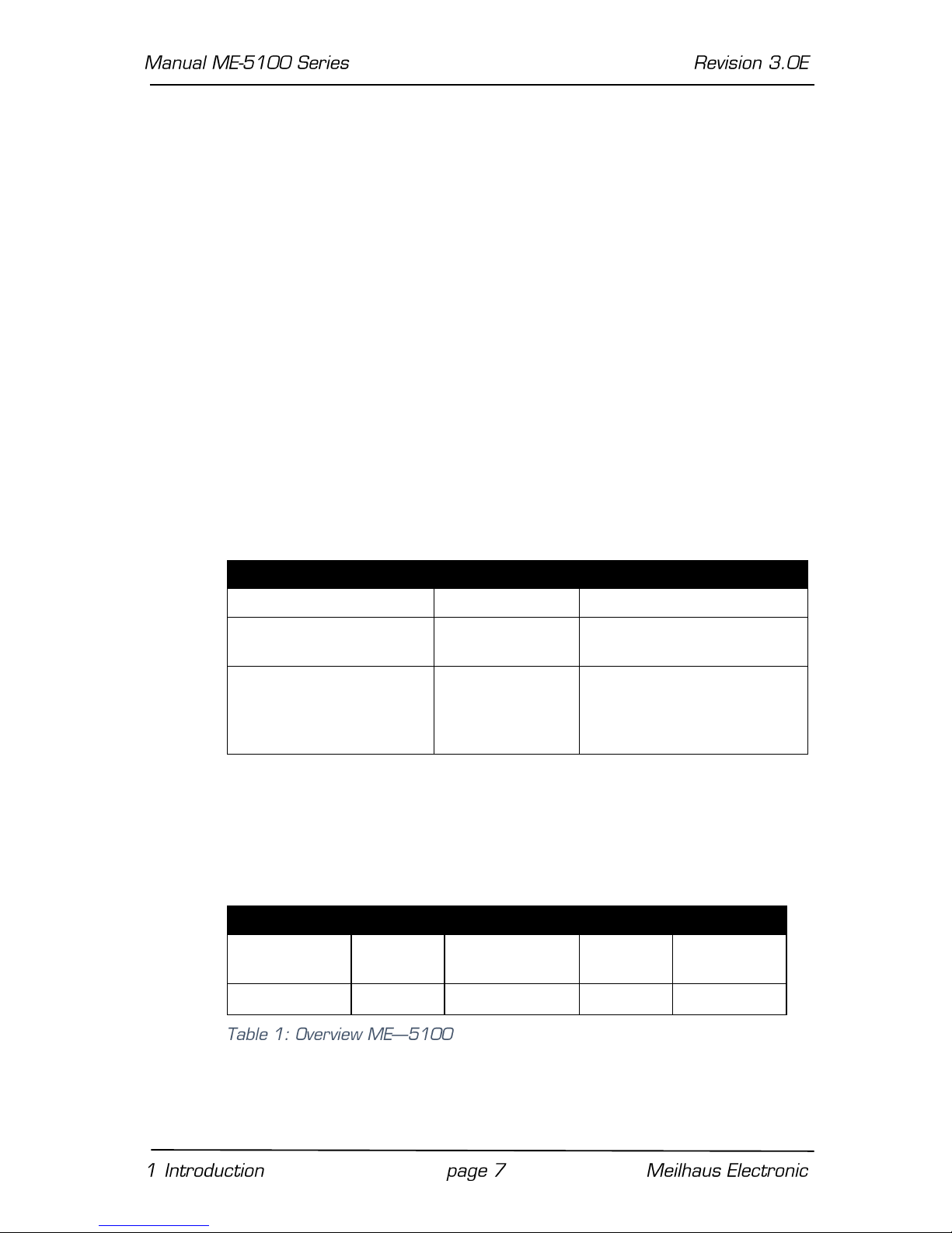
There are different versions of ME-5100:
Model
TTL I/Os/Counters
ME-5100 PCIe/cPCI
ME-5100
32 I/O, TTL
ME-5100A PCIe/cPCI
ME-5100 + ME5001
32 I/O, TTL
ME-5100B PCIe/cPCI
ME-5100 + ME5004
32 I/O, 16 inputs, 16 outputs, opto-isolated,
3 counters, 16 bit, optoisolated
The ME-5100 is a fast digital-I/O board for the PCI-Express- and
CompactPCI-systems. The base board can optionally be extended
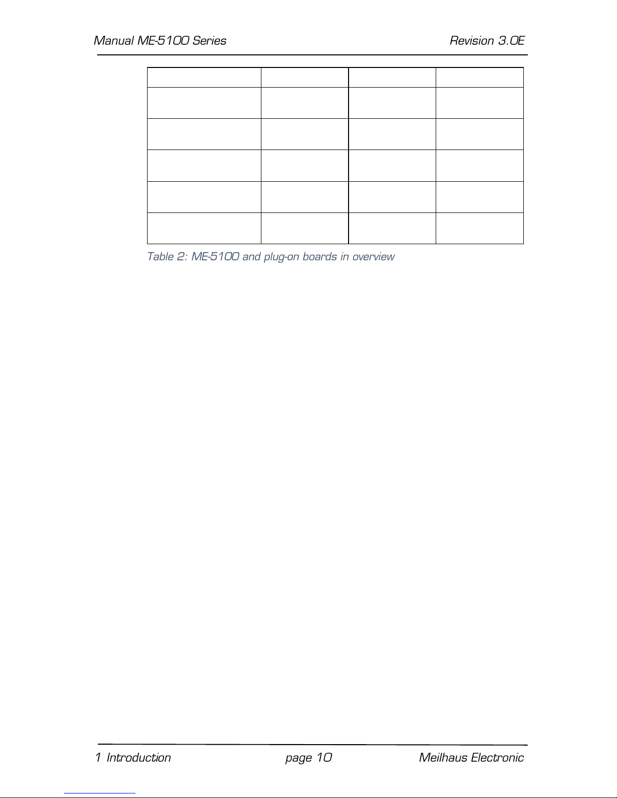
with plug-on boards (see Table 2 on page 10).
Overview:
Model
DIO
FIO*
3.3 V/5 V
Termination
ME-5100
(subdevice 0)
16 bit DIO
4 FI channels
✔
✔
(subdevice 1)
16 bit DIO
4 FO channels
✔
✔
*Alternative configuration can be activated via ME-iDC.
Page 8

High-speed digital-I/O ports: The ME-5100 has two 16-bit digi-
tal-I/O ports and a number of control lines. When operating in
single mode, the two ports can be configured, independently of
one another, as input or output. The direction of the ports is
defined in software. Immediately after powering up, all the
ports are configured as inputs. When operating in streaming
mode, the direction of the ports is specified by hardware: port
A is the input port, while port B is the output port.
Frequency counter: The concept of the “configurable subde-
vices” allows subdevice 0 to be employed as a frequency counter. Four independent channels are available for measuring the
frequency and duty cycle of rectangular signals (max. 5.5 MHz).
Pulse generator: The concept of the “configurable subdevices”
allows subdevice 1 to be employed as a rectangular wave generator. Four independent channels are available for the output of
a periodic, rectangular signal at up to 5.5 MHz with a variable
duty cycle.
Signal level 3.3/5 V: the signal level of all the digital inputs/out-
puts and of the control lines can be switched together between
3.3 V and 5 V, depending on the external circuitry.
For optimum signal matching, you are able to activate, via soft-
ware, an active 110 Ω termination at the digital inputs/outputs
of each port.
The DATA_VALID and L_CLK signals are available for synchroni-
zation with the external circuitry. The DATA_VALID pin indi-
cates the validity of the data during output in streaming mode
operation, while the 66 MHz system clock can be accessed at
the L-CLK pin.
Bit-pattern detection: The bit-pattern at the digital inputs can
be monitored if required. Depending on the configuration, an interrupt can be triggered in response to a change in the bit-pattern. In streaming mode operation, the bit-pattern detection
can also be used to control the input/output operation, depending on the selected operation mode (not using interrupts).
Thanks to the DMA architecture, the data can be transferred very
quickly between the PC’s working memory and the board. In
streaming mode, an input/output rate of up to 30 MS/s, in which all
the ports must participate, is possible. (See also Table 3 on page
22). The actual transmission rate will depend on the operating
mode and the configuration of your computer.
Depending on requirements, you can select from the following oper-
ating modes:
Page 9
Single: In this operating mode, a single value can be read or
written under software control (see chapter 4.1.1 on page 24).
Streaming: Data is read in/output in this operating mode via a
FIFO. It is possible to choose between a timer and/or external
trigger signals for timing control. A large number of trigger op-
tions, with which you can define start and stop conditions, are
available. Port A is specified as a 16-bit input port, and Port B
as a 16-bit output port (see chapter 4.2 on page 27).
Interrupt: For interrupt handling in the “bit-pattern change”
and “bit-pattern comparison” modes (see chapter 4.3 on page
30).
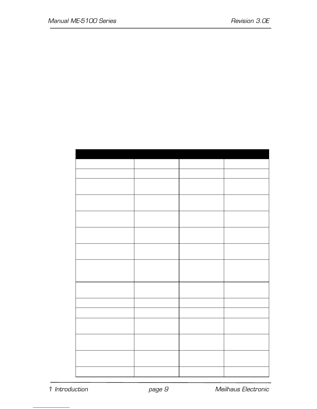
Customer-specific versions of the firmware are available on request.
Model
ME-5100
ME-5001
ME-5004
PC interface
cPCI/PCIe
- - Board type
base board
plug-on board
plug-on board
DIO channels
2 x 16 bit DIO
4 x 8 bit DIO
1 x 16 bit DI
1 x 16 bit DO
Streaming
channels
1 x 16 bit DI 1
x 16 bit DO
-
-
DI/DO/ I/O rate
30 MS/s /
30 MS/s
- - FI/FO frequency
5.5 MHz/
5.5 MHz
5.5 MHz/
5.5 MHz
300 kHz/
3 kHz
External trigger for
streaming
✔
-
-
Software Start/Stop
for streaming mode
operation
✔
-
-
Frequency
measurement
4 channels
8 channels
8 channels
Pulse generator
4 channels
8 channels
8 channels
Bit-pattern change
✔ ✔ ✔
Bit-pattern
compare
-
-
✔
DI/FI level
3.3 V/5 V (TTL)
3.3 V/5 V (4 x
8 bit**)
3…60 V
DO/FO level
3.3 V/5 V (TTL)
3.3 V/5 V (4 x
8 bit**)
15…30 V
Active termination
✔
4 x 8 bit**
-
Page 10
Opto-isolation
-
-
✔
Sink/source
selection
-
-
✔
Temperature
monitoring
-
-
✔
External wiring
78-pin D-Sub
socket
25-pin D-Sub
socket
37-pin D-Sub
socket
Configurable
firmware
✔ ✔ ✔
Configurable
subdevices
✔ ✔ ✔
*opt. via ME-AK-D25F/S (cPCI) **only for subdevices 0..3
1.4 System Requirements
The ME-5000 series may be installed into any PC with PCIExpress- resp. CompactPCI-slot (32 bit, 33 MHz, 5 V). The board
is supported by the Meilhaus Electronic Intelligent Driver System
(ME-iDS).
1.5 Software Support
The ME-5000 series is supported by the Meilhaus Electronic Intelligent Driver System (ME-iDS). The ME-iDS is a unique driver system covering different devices and operating systems. It supports
Windows 2000, XP, Vista, 7, 8.1, 10 and contains a universal
function library (API) for all common programming languages.
A detailed description of the functions can be found in the ME-iDS
manual on the CD/DVD enclosed.
Please also note the corresponding README-files.
Page 11
2 Starting up
Please read your computer’s instruction manual on how to install
new hardware components before installing the board.
2.1 Software Installation
• Installation under Windows
The following basic procedure should be used:
If you have received the driver software as an archive file please unpack the software before installing the board. First choose a directory on your computer (e.g. C:\Temp\Meilhaus\ME-iDS).
Use the Meilhaus Electronic Intelligent Driver System (ME-iDS) for
programming your new data acquisition hardware. For installation
and operation of the driver system please follow the documentation
in electronic form included with the software package.
2.2 Test Program
ME-PowerLab3: Run the program from the Windows Start menu.
This will allow you to test all the important functions of the hardware.
For simple testing of the board use the corresponding test program provided with the ME-iDS.
Page 12
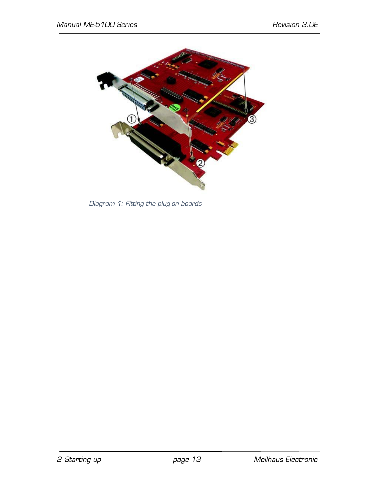
2.3 Fitting the Plug-on Boards
The boards should be handled with care in order to make sure that
the device is not damaged by electrostatic discharge (ESD), mechanical stress or unsuitable current surges. Precautions should
also be taken to avoid an electric shock. Ensure that standard ESD
safety precautions are taken. At least one hand should be
grounded in order to dissipate any static charge.
Observe the following procedure:
1. If the base board is installed, you must first remove it in or-
der to be able to insert the plug-on board. Here you should
observe the procedure as described in the manual for your
PC system.
2. Make sure that electrostatic discharges cannot take place
through the plug-on board or the base board as you plug it
in. Follow the standard ESD safety precautions.
3. Push the plug-on board carefully, and with only a little force,
on to the male connector provided for it (see Diagram 1,
items 1, 2 and 3). Check that the board is fully plugged in.
4. Choose two adjacent slots for the installation. If necessary,
remove an additional mounting bracket for the slot of the
plug-on board.
5. Carefully plug the combination of the base and plug-on board
into the computer.
6. Screw the two slot brackets down firmly.
7. Close the PC system again.
Page 13
2.4 Power Supply for PCI-Express Models
Because of the PCI-Express slot drive’s insufficient current for operating the board, an additional supply is required via the PC power
supply. For that purpose connect a free “MOLEX” connector of the
PC (as used for power supply of drives) with the appropriate terminal of the board (see the following diagram). Otherwise the board
may be irreversibly damaged!
Page 14

Page 15

3 Hardware
3.1 Block Diagram
Subdevice 0 (port A) Single mode operation: bidirectional,
specified as an input port for operation in streaming mode.
Subdevice 1 (port B) Single mode operation: bidirectional,
specified as an output port for operation in streaming mode.
*SPI:”Serial Programming Interface”
The pin assignment for the 78-pin D-Sub socket can be found in
the appendix (see “Pinout” on page 36).
You will find a description of the circuitry of the individual function
groups in the following sections. Please read the chapter 4 from
page 22 for operating modes and programming.
Page 16

3.2 ME-5100 cPCI
3.3 ME-5100 PCIe
Page 17

3.4 Digital Input/Output
The ME-5100 has two 16-bit digital-I/O ports and a number of control lines. When operating in single mode, the two ports can be
configured, independently of one another, as input or output. The
direction of the ports is defined in software. When operating in
streaming mode, the direction of the ports is specified by hardware: port A is the input port, while port B is the output port.
In streaming mode, ports A and B must share the bandwidth for
the data transfer between the board and the PC. This depends on
the configuration of your computer - a total data throughput of up
to 30 MS/s is realistic (see also Table 4 on page 23).
Please read chapter 4.1.1 from page 24 for programming the different operating modes.
3.4.1 Digital Inputs
When wiring the inputs, note that the voltage level must be observed (see the specifications on page 32) and that a reference to
the PC ground (GND_PC) must be established (see Diagram 6).
Page 18

3.4.2 Digital Outputs
When wiring the outputs, note that the voltage level must be observed (see the specifications on page 35) and that a reference to
the PC ground (GND_PC) must be established (see Diagram 6).
I
Out
= I
OL
= IOH = 24 mA per pin.
3.4.3 External Trigger
3.4.3.1 External Trigger Inputs
In addition to the trigger inputs TRIG_A and TRIG_B, any of the digital inputs can also be used as a trigger input. You can therefore
configure the trigger conditions for starting and stopping a timercontrolled input/output (streaming mode operation) very flexibly.
See also Diagram 7 on page 18, and the trigger matrix, Diagram
12 on page 29.
The specifications for the digital inputs apply to the wiring of the
trigger inputs TRIG_A and TRIG_B.
Note: The input/output cannot be externally triggered in single
mode operation. Compare here chapter 3.6 “External Interrupt” on
page 20.
3.4.3.2 Edge Detection
You can specify, both for the trigger inputs TRIG_A and TRIG_B and
for all the usable digital inputs, whether the operation is to be
started by a rising edge, falling edge, or by any edge (i.e. equally by
rising or falling edges).
Page 19

3.5 Frequency Input/Output
The concept of the „configurable subdevices“ of the ME-5000 series gives you the option of using individual subdevices with an alternative functionality. The associated configuration is carried out
with the ME-iDC configuration tool before your application is called.
The following channels are available:
Frequency counter (FI = “Frequency Input”):
4 independent inputs for measuring the frequency and duty cycle of rectangular signals (max. 5.5 MHz).
Pulse generator (FO = “Frequency Output”):
4 independent outputs for the output of a periodic rectangular
signal at up to 5.5 MHz with a variable duty cycle.
The associated pins are identified as FI_A0..3 and FO_B0..3 in the
terminal assignment on page 37. In this configuration, the remaining inputs/outputs of the digital ports cannot be used.
Please note: In the “pulse generator” (FO) configuration, the un-
used pins DIO_B4..15 are connected to ground!
The specifications for the digital-I/O ports apply to the wiring of the
inputs and outputs. A reference to the PC ground (PC_GND) must
always be established. The maximum output current is I
OUT
= IOL =
IOH = 24 mA.
The frequency counters and pulse generators are configured by
software. Please read chapter 4.1.2 on page 25 for programming
the frequency input/output.
Page 20

3.6 External Interrupt
If required, you can also monitor the bit-pattern of a digital input
port. The “bit-pattern change” mode is available on the ME-5100.
As soon as the specified event occurs, an interrupt is issued and
passed directly to the PC.
The digital inputs/outputs are programmed in the single operating
mode. The interrupt handling is carried out with the functions; see also chapter 4.3 on page 30.
3.7. Additional Functions
You can make the following settings for adapting to your application
regardless of the operating mode.
3.7.1 System Clock Output
If required, you can output the 66 MHz clock (L_CLK) at pin 29 of
the 78-pin D-Sub connector. A 100 Ω resistor must be fitted at
R55 for this purpose. You can find the position of R55 with the aid
of Figs. 4 and 5 (page 16).
Note: Remember that crosstalk between the clock and the signal
lines can easily happen in the external wiring. We recommend use
of the optional ME AB-D78/IDC adapter board, where a ground line
is included between each signal line. Used together with a suitable
ribbon cable, you can minimize the crosstalk in this way.
3.7.2 Termination
For optimum signal matching, you can enable via software, an active 110 Ω termination at the digital inputs/outputs of each port.
The termination circuits are effectively protected against overload
by the combination of current limiting and thermal shutdown (with
automatic return to service).
Page 21

3.7.3 Logic Level Matching
The signal level of all the digital inputs/outputs and of the control
lines can be switched together between 3.3 V and 5 V, depending
on the external circuitry. The changeover is made for all the ports
of the base board at once using software.
3.7.4 ”DATA_VALID” Pin
A high level at the DATA_VALID output indicates the validity of the
data at output port B in streaming mode operation.
Page 22

4 Programming
For programming the device please use the Meilhaus Electronic Intelligent Driver System (ME-iDS) included in your package. The MEiDS is a unique driver system covering different devices and operating systems. It supports Windows 2000 and higher and contains a
universal function library (API) for all common programming languages (the extent of the current software support can be found in
the README-files of the ME-iDS).
A detailed description of the functions can be found in the ME-iDS
manual (see CD/DVD enclosed or online:
www.meilhaus.de/download/ME-iDS.
Further details regarding the assignment of the subdevices and device specific arguments can be found in the help file (help file format
under Windows, *.chm) which can be accessed via the „ME-iDS
Control Center“ in the info area of the task bar (as a rule in the
lower right corner of the screen) or via the Windows start menu.
The ME-5100 base board is a device with two "subdevices", beginning with the index "0". When a plug-on board (e.g. the ME-5001) is
used, further subdevices (starting with the index "0") are added.
The functionality of the subdevices can be specified by the user
through selecting a pre-defined configuration. The desired configuration is loaded into the board by the ME-iDC configuration tool before your application starts. Using the standard configuration, (ID
0), the board is ready to operate immediately. You will find an overview of the currently available configurations in the following table:
Subdevice of Type
…Subtype
I/Os
ID of the
Configuration
Subdevice 0 (DIO, DI, FO)
Digital input (DI)
streaming
16-bit port
0*
Digital input/output (DIO)
single
16-bit port
1
Frequency input (FI)
single
4 channels
2
Page 23

Subdevice of Type
…Subtype
I/Os
ID of the
Configuration
Subdevice 0 (DIO, DI, FO)
Digital output (DO)
streaming
16-bit port
0*
Digital input/output (DIO)
single
16-bit port
1
Frequency output (FO)
single
4 channels
2
*Standard configuration at shipment. The most recently selected
configuration in the ME-iDC is stored in a non-volatile memory on
the board, and is automatically loaded after a restart.
Depending on requirements, you can select from the following operation modes:
Single: Individual values can be read or written in this operating
mode.
Streaming: Data is read in/output in this operating mode via a
FIFO. It is possible to choose between a timer and/or external
trigger signals for timing control. A large number of trigger options, with which you can define start and stop conditions, are
available. See chapter 4.2 starting on page 27.
Interrupt: For the interrupt handling in the bit-pattern change
mode (see chapter 4.3.1 starting on page 31).
Operation Mode
Speed
Trigger
Single
single value
input/output via software
Stream-Timer …with
„wraparound“ option
up to 30 MS/s
(depending on the
computer)
start/stop by software
of by external trigger
Stream-Trigger-Sample
up to 30 MS/s
(depending on the
computer)
start/stop by software
of by external trigger
Interrupt (Bit-pattern
detection)
f
IRQmax.
= 10 kHz
ext. trigger signal at a
digital input/output port
Comprehensive timing diagrams will be found in the ME-iDS manual.
**see chapter 4.2 starting on page 27.
Page 24

4.1 Single Operation Mode
Individual values can be read or written in this operating mode.
Notes:
In the single operating mode, the ports of the ME-5100 can be
used bi-directionally.
Immediately after powering up, the bidirectional ports are con-
figured as inputs.
In streaming mode, port A is specified as input and port B as
output.
A port that is configured as an output can also be read back!
4.1.1 Digital Input/Output
The input/output of individual digital values is carried out in the single operating mode. Each digital port is addressed as a function
group of type ME-TYPE_DIO subtype ME_SUBTYPE_SINGLE. Ports
A and B can optionally be configured as 16-bit input or output
ports.
Please observe the ME-iDS manual and the ME-iDS help file (*.chm)
for the procedure. You can open both these documents through
the “ME-iDS Control Center” or through the Windows Start menu.
Please read chapter 3.4 on page 17 for wiring of the digital ports.
ME-5100
ME-5001
ME-5004
✔ ✔ ✔
Page 25

4.1.2 Frequency Input/Output
Before you can use the “Frequency measurement” or “Pulse generator” modes, it is necessary, before opening your application, to
run the ME-iDC configuration tool in order to specify the configuration for the corresponding subdevice (see also Table 3 on page 22).
The programming of the frequency measurement and the pulse
generator is always done in the single operating mode. The subtype of the subdevices is always ME-SUBTYPE_SINGLE.
Please read the ME-iDS manual and the ME-iDS help file (*.chm)
carefully prior to programming. You can open both of these documents through the “ME-iDS Control Center” or through the Windows Start menu.
Two variables are introduced to describe the rectangular signal,
and apply equally to input and output. One value indicates the period T, while the other value provides the duration of the pulse of
the first phase of the period t1p. For frequency measurement, the
measurement starts with the first rising edge, and finishes with
the next rising edge. The falling edge that lies between them defines the end of the first phase. In pulse generator mode, output
normally starts with a high level, changing to the low level when the
first phase has elapsed.
ME-5100
ME-5001
ME-5004
✔ ✔ ✔
Page 26

The time reference is provided by a 66 MHz counter. It is configured using the function. A period of 15.15 ns follows from this, and is defined as the smallest unit of time. It is re-
ferred to below as “1 tick”. The resolution for T and t1P is therefore
1 tick (see also the specifications on page 32).
Note that the value of the maximum period T
max
. depends on the
duty cycle. A distinction is drawn between rectangular signals with
an asymmetrical duty cycle T
max. asym
. and a symmetrical duty cycle
T
max. sym
. The figures for the ME-5100 are:
T
max. asym
. = 32.5 s (0.03 Hz); T
max. sym
. = 65 s (0.015 Hz)
The wiring of the frequency inputs/outputs can be found in chapter
3.5 on page 19.
4.1.2.1 Frequency Measurement
With the frequency measurement operating mode (FI=”Frequency
Input”) you can determine the period or frequency, and the duty cy-
cle of rectangular signals up to about 5.5 MHz. The resolution is 1
tick = 15.15 ns. The measurement always starts at a rising edge.
On the ME-5100, all 4 frequency measuring channels (FI_AO…3)
are addressed as subdevices of type ME_TYPE_FI, subtype
ME_SUBTYPE_SINGLE. Each channel can be programmed independently.
Note: If the frequency and duty cycle are the magnitudes you want,
these can easily be calculated from the values returned for
<pdTime>. The formula is:
Frequency [Hz] = 1/period [s]
Page 27

Duty cycle [%] = („duration of the first phase of the period“ [s]/pe-
riod [s] x 100.
4.1.2.2 Pulse Generator
In the pulse generator operating mode (FO = “Frequency Output”)
you can output rectangular signals with a variable duty cycle at frequencies of up to 5.5 MHz and with a resolution of 1 tick. On the
ME-5100, all 4 pulse generator channels (FO_B0…3) are ad-
dressed as a subdevices of type ME_TYPE_FO, sub-type ME_SUBTYPE_SINGLE. Each channel can be programmed independently.
The first phase of the rectangular signal is “high” by default. By
setting the ME_IO_SINGLE_TYPE_FO_START_LOW flag it is also
possible to start the output with a “low” level.
Note: An output channel can also be read back!
4.2 Streaming Operation Mode
4.2.1 Digital Input/Output
The programming of the timer-controlled input/output via FIFO is
carried out in the streaming operating modes. The 16 pins of subdevice 0 are specified as inputs (subdevice of type ME_TYPE_DI),
while the 16 pins of subdevice 1 are specified outputs (subdevice of
type ME_TYPE_DO), all of these having the sub-type ME_SUBTYPE_STREAMING.
Please observe the ME-iDS manual and the ME-iDS help file (*.chm)
for the procedure. You can open both of these documents through
the “ME-iDS Control Center” or through the Windows Start menu.
ME-5100
ME-5001
ME-5004
✔
-
-
Page 28

4.2.1.1 Stream Timer
In this operating mode the values are acquired or output under the
control of a timer. A continuous transfer bandwidth between the
PC and the ME-5100 of up to 30 MHz is available. This must be divided between all the subdevices (measured with a dual core computer running under Windows 7 – it will depend on your computer
configuration).
4.2.1.2 Stream Trigger Sample
In this operating mode individual values can be acquired or output
under the control of one or more external trigger signals. A continuous transfer bandwidth between the PC and the ME-5100 of up
to 30 MHz is available. This must be divided between all the subdevices (measured with a dual core computer running under Windows
7 – it will depend on your computer configuration).
4.2.1.3 Burst Mode
In what is known as the “burst mode” you can read a maximum of
8192 data words from subdevice 0, or output them on subdevice
1, at a guaranteed rate of 33 MS/s. The transfer to and from the
PC is carried out at a maximum of 30 MHz.
4.2.1.4 Wraparound Mode
This option is used for the repeated output of one and the same
data buffer on subdevice 1.
Note: When no more than 8192 values are to be output for an indefinitely long period at an output rate of at most 7.4 MS/s (at
least 9 ticks), this is done on firmware level of the ME-5100 without loading the host computer.
4.2.1.5 External Trigger
The trigger conditions for starting and stopping the streaming operating mode can be selected very flexibly. It is thus possible to enable one or more trigger inputs individually, with specification of the
desired trigger edge (rising, falling, or any). All the enabled trigger
inputs are logically ORed together. This means that the first edge
to arrive that meets the trigger condition starts or stops the input/output operation, according to the selected operation mode
(stream timer or stream trigger sample). In other words, any
change of the bit-pattern can be used as a trigger event for the
subdevice concerned.
Page 29

Trigger signals from TRIG_A or the inputs DIO_A0…15 can be used
for subdevice 0, while for subdevice 1 the trigger signals from
TRIG_B and any of the inputs DIO_B0..15 can be used (see Diagram
12 on page 29).
Page 30

4.3 Interrupt Operation
On the ME-5100 you can monitor the bit-pattern of a digital-I/O
port configured as an input for changes in one or more masked
bits. As soon as the first edge that meets the trigger condition
arrives, an interrupt is generated and passed directly to the PC. A
digital port used for bit-pattern detection must be of type
ME_TYPE_DIO or ME_TYPE_DI.
The programming is carried out in the single operating mode.
Note: TRIG_A and TRIG_B can also be used as interrupt inputs with
the aid of the property functions (see the ME-iDS help file).
Please observe the ME-iDS manual and the ME-iDS help file (*.chm)
for the procedure. You can open both of these documents through
the “ME-iDS Control Center” or through the Windows Start menu.
ME-5100
ME-5001
ME-5004
✔ - ✔
Page 31

4.3.1 Bit-pattern Change
In the bit-pattern change mode, one or more bits that are to be
monitored for a change of state can be defined (masked). A
32-bit-wide argument per subdevice contains the mask. For each
input pin both one bit for rising edge and one bit for falling edge is
available. If the state of at least one bit masked with a “1” changes
(0 1 or 1 0), an interrupt is issued (see diagram 14 on
page 31).
In what is known as the “extended format” of interrupt handling
(see the ME-iDS manual), two bits are available for the interrupt
status of each pin. One is for the rising edge, and one for the
falling edge. The bits for the falling edges are assigned to the bit
b15…0, while the bits for the rising edges are assigned to the bits
b31…16.
Example (see diagram 14):
By writing the value 00800004 Hex as a mask value (see parameter <iIrqArg> of the function bit 2 is monitored for
a falling edge, and bit 7 for a rising edge. A rising edge now is to
arrive at bit 7, so that an interrupt is issued and in the interrupt
status value bit b23 returns “1”. Any edges that might arrive at
pins labelled with an “X” are ignored. Only the change in state of a
pin whose edge is set to “1” in the parameter <iIrqArg> can is-
sue an interrupt.
The interrupt event is evaluated with the function
We recommend using what is known as the “extended format” to
obtain detailed information about the triggering edge.
Page 32

5 Appendix
A Specification
PC Interface
PCI-Express bus
32 bit, 33 MHz, 3.3 V, PCI-Express x 1 specification
version 2.0
CompactPCI bus
32 bit, 33 MHz, 5 V, PICMG 2.0 R3.0
Plug&Play
is fully supported
Digital Input/Output
Measured
Quantity/criterion
Condition/
Explanation
Value
Ports
subdevice 0 single mode
operation
16-bit-bidirectional
subdevice 0 streaming
mode operation
16-bit input port
subdevice 1 mode operation
16-bit bidirectional
subdevice 1 streaming
mode operation
16-bit output port
Operating modes
single
software-triggered reading/writing
stream timer
timer-controlled reading/writing of the values
via FIFO
stream trigger sample
trigger-controlled reading/writing of the values
via FIFO
interrupt
monitoring the digital
ports for a change in the
bit-pattern
FIFO size
FIFO_IN
8192 values (16-bit-wide)
FIFO_OUT
8192 values (16-bit-wide)
Transfer rate in
streaming mode
between the ME-5100
and PC
max. 25 MHz (cPCI) resp.
30 MHz (PCIe) (systemdependent)
Page 33

Input/output rate
in streaming mode
continuous (total for
both ports)
max. 25 MS/s (cPCI) resp.
30 MS/s (PCIe) (systemdependent)
„burst“-option
(input/output of up to
8192 values)
max. 33 MS/s per channel, transfer: see transfer
rate
„wraparound”-option
(total for both ports)…
if f
max
. <7.4 MS/s and
the number of values ≤
8192 and the number of
repetitions is „infinite“
max. 25 MS/s (cPCI) resp.
30 MS/s (PCIe) (systemdependent)
max. 7.4 MS/s (without
loading the host PC)
Timer (CHAN
time)*
programmable in steps
15. 15 ns
(1 tick)
30.30 ns …65 s
(2..FFFFFFF Hex ticks)
External trigger
inputs
TRIG_A, TRIG_B, DIO_Ax,
DIO_Bx
External trigger
edges
rising, falling, any
Output level:
UOL
at I
OUT
= 24 mA
max. 0.5 V
U
OH 3.3V
at I
OUT
= -24 mA
min. 2.4 V
U
OH 5V
at I
OUT
= -24 mA
min. 2.4 V
Input level:
UIL
at Vcc =3.3 V or 5 V
max. 0.8 V
U
IH 3,3V
at Vcc = 3.3 V
min. 2 V
U
IH 5V
at Vcc = 5 V
min. 2 V
Input current:
IIN
±1 μA
Output current:
I
OUT
per pin
max. 24 mA
Reference ground
PC ground (GND_PC)
*Due to the nature of the system, boards that are not fitted into the
ME Synapse do not reach the full sampling rate. The sampling rate that
can actually be achieved depends heavily on the capacity of your computer and on the number of USB devices connected.
Page 34

Frequency Input/Output
Availability
alternative subdevice configuration via ME-iDC
Signal form
rectangular
Frequency Measuring Channels
Measured
Quantity/Criterion
Condition/
Explanation
Value
Reference ground
PC ground (GND_PC)
Number of channels
(FI_A0…3)
4 inputs (TTL)
Input level
see digital I/O
Input current
see digital I/O
Period (T)
T
min
. =T
min.asym.=Tmin.sym
.
T
max.asym
T
max.sym
181. 81 ns (5.5 MHz)
32.5 s (0.03 Hz) 65 s
(0.015 Hz)
Duty cycle
variable, depending on T
measurable in steps
of 1 tick
Resolution
1 tick
15.15 ns
Accuracy
±15.15 ns
Operating modes
Single
Pulse Generator Channels
Measured
Quantity/Criterion
Condition/
Explanation
Value
Reference ground
PC ground (GND_PC)
Number of channels
(FI_B0…3)
4 outputs (TTL)
Output level
see digital I/O
Period (T)
T
min
. =T
min.asym.=Tmin.sym
.
T
max.asym
T
max.sym
181.81 ns (5.5 MHz)
32.5 s (0.03 Hz) 65 s
(0.015 Hz)
Duty cycle
variable, depending on T
adjustable in steps 1
tick
Resolution
1 tick
15.15 ns
Accuracy
±15.15 ns
Operating modes
single
Page 35

Interrupt
Measured
Quantity/Criterion
Condition/Explanation
Value
Interrupt sources
passed directly to the PC
bit-pattern change
General Data
Measured
Quantity/Criterion
Condition/Explanation
Value
Power supply
CompactPCI
+5 V (via PCI bus)
PCI-Express
+3.3 V (via PCIe bus)
+5 V (via Molex plug
from PC power
supply unit)
Current consumption
CompactPCI
0.8...1.2 A (full load)
PCI-Express
0.8…1.2 A (full load)
Board dimensions
(without mounting
bracket and connector)
PCI-Express
162 mm x 98 mm
CompactPCI
3 HE CompactPCI
board
Connections
ST1
78-pin D-Sub female
socket
IDC connectors for
plug-on board
Operating
temperature
0…70 °C
Storage
temperature
-40…100 °C
Air humidity
20…55 %
(non-condensing)
Certification
CE
Page 36

B Pinout
Legend for pinouts:
Pin-name
Function
DI_A0..15
digital input/output (subdevice 0)
DO_B0..15
digital input/output (subdevice 1)
TRIG_A
digital trigger input for subdevice 0
TRIG_B
digital trigger input for subdevice 1
DATA_VALID
output indicating the validity of the data at
outputs DIO_B0…15 in streaming mode
L_CLK
local clock output (66 MHz). Not connected by default –
if necessary, can be brought to the connector (ST1) by
fitting R55 (see page 16 for position of R55).
FI_A0…3
frequency measuring inputs (alternative configuration)
FO_B0…3
pulse generator outputs (alternative configuration)
GND_PC
common ground (=PC ground)
„Reserved“
pin reserved for extensions
These pins must not be connected. Otherwise the
board may be irreversibly damaged!
Page 37

B1 78-pin D-Sub (ST1) – ME-5100
*Use as a frequency measuring input or pulse generator. Output is
only possible after appropriate configuration using ME-iDC. The
other pins of the relevant digital port (DIO_A4…15 or DIO_B4…15)
can then no longer be used for digital input/output.
Note that the unused pins DIO_B4…15 are connected to ground
for frequency output (FO)!
Page 38

B2 Adapter Board – ME AB-D78/IDC
The optional ME AB-D78/IDC adapter board (78-pin D-Sub connector to male connector) carries a ground line between every signal line. Used together with ribbon cables, you can thus minimize
the crosstalk.
The pin assignment of the 78-pin D-Sub connector ST1 corresponds to ST1 on the ME-5100 (see Diagram 15).
Additional signals (ST3):
ST3 Pin
Name (ST1 pin)
ST3 Pin
Name (ST1 pin)
1
TRIG_A (31)
2
GND_PC
3
TRIG_B (11)
4
GND_PC
5
reserved (30)
6
GND_PC
7
DATA_VALID (10)
8
GND_PC
9
L_CLK (29)
10
GND_PC
11
reserved (70)
12
GND_PC
13
GND_PC
14
GND_PC
15
GND_PC
16
GND_PC
Page 39

17
GND_PC
18
GND_PC
19
GND_PC
20
GND_PC
Subdevice 0 (ST4)
ST4 Pin
Name (ST1 pin)
ST4 Pin
Name (ST1 pin)
1
DIO_A0/FI_A0 (20)
2
GND_PC
3
DIO_A1/FI_A1 (39)
4
GND_PC
5
DIO_A2/FI_A2 (58)
6
GND_PC
7
DIO_A3/FI_A3 (77)
8
GND_PC
9
DIO_A4 (18)
10
GND_PC
11
DIO_A5 (37)
12
GND_PC
13
DIO_A6 (56)
14
GND_PC
15
DIO_A7 (75)
16
GND_PC
17
DIO_A8 (16)
18
GND_PC
19
DIO_A9 (35)
20
GND_PC
21
DIO_A10 (54)
22
GND_PC
23
DIO_A11 (73)
24
GND_PC
25
DIO_A12 (14)
26
GND_PC
27
DIO_A13 (33)
28
GND_PC
29
DIO_A14 (52)
30
GND_PC
31
DIO_A15 (71)
32
GND_PC
33
GND_PC
34
GND_PC
35
GND_PC
36
GND_PC
37
GND_PC
38
GND_PC
39
GND_PC
40
GND_PC
Subdevice 1 (ST2)
ST2 Pin
Name (ST1 pin)
ST2 Pin
Name (ST1 pin)
1
DIO_B0/ (FO_B0)
2
GND_PC
3
DIO_B1/(FO_B1)
4
GND_PC
5
DIO_B2/(FO_B2))
6
GND_PC
7
DIO_B3/(FO_B3))
8
GND_PC
Page 40

9
DIO_B4
10
GND_PC
11
DIO_B5
12
GND_PC
13
DIO_B6
14
GND_PC
15
DIO_ B7
16
GND_PC
17
DIO_ B8
18
GND_PC
19
DIO_ B9
20
GND_PC
21
DIO_ B10
22
GND_PC
23
DIO_ B11
24
GND_PC
25
DIO_ B12
26
GND_PC
27
DIO_ B13
28
GND_PC
29
DIO_ B14
30
GND_PC
31
DIO_ B15
32
GND_PC
33
GND_PC
34
GND_PC
35
GND_PC
36
GND_PC
37
GND_PC
38
GND_PC
39
GND_PC
40
GND_PC
Page 41

C Accessories
We recommend to use high-quality connector cables with singleshielded lines per channel.
For further accessories please refer to the current Meilhaus Electronic catalog and the internet:
www.meilhaus.de/en/pc-boards/accessories/
Page 42

D Technical Questions
D1 Hotline
Should you have questions or inquiries concerning your Meilhaus
device, please contact us:
Meilhaus Electronic GmbH
Repair & Service
Am Sonnenlicht 2
D-82239 Alling
Sales: Support:
Tel.: (08141) 52 71 – 0 Tel.: (08141) 52 71 – 188
Fax: (08141) 52 71 – 129 Fax: (08141) 52 71 – 169
eMail: sales@meilhaus.de eMail: support@meilhaus.de
Download-Server and Driver Update:
To download current driver versions for Meilhaus Electronic devices
as well as manuals in PDF format, please go to:
www.meilhaus.org/driver
Service Department with RMA Process:
In case you need to return a board for repair purposes, we strongly
ask you attach a detailed description of the error as well as information regarding your computer/system and the software used.
Please register online using our RMA process:
www.meilhaus.de/en/infos/service/rma.htm.
Page 43

E Index
A
Accessories .................................................................... 41
Additional Functions...................................................... 20
Appendix ....................................................................... 32
B
Block Diagram ............................................................... 15
D
Digital Input/Output ...................................................... 17
E
External Interrupt .......................................................... 20
External Trigger ............................................................. 18
F
Features........................................................................... 7
Frequency Input/Output ............................................... 19
H
Hardware ....................................................................... 15
Hotline ........................................................................... 42
I
Interrupt Operation ...................................................... 30
Introduction .................................................................... 5
M
ME-5100 cPCI ................................................................ 16
ME-5100 PCIe ................................................................ 16
P
Package Contents ............................................................ 7
PCI-Express Models ....................................................... 13
Pinout ............................................................................ 36
Plug-on Boards .............................................................. 12
Programming ................................................................ 22
Pulse Generator ............................................................ 27
S
Single Operation Mode ................................................. 24
Software Installation ..................................................... 11
Software Support .......................................................... 10
Specifications ................................................................ 32
Streaming Operation Mode .......................................... 27
System Requirements ................................................... 10
T
Technical Questions ...................................................... 42
Test Program ................................................................. 11
 Loading...