

Page 1
Meilhaus Electronic Manual
ME-5810 Series
Opto-Isolated Digital-I/O Board
with Bit-Pattern Detection, 3 x 16-bit Counters (8254)
(alternatively: Frequency Measurement and Pulse Generator)
Page 2

Imprint
Manual ME-5810 Series
Revision 2.0
Revised: 2019-09-10
Meilhaus Electronic GmbH
Am Sonnenlicht 2
D-82239 Alling bei München
Germany
www.meilhaus.de
© Copyright 2019 Meilhaus Electronic GmbH
All rights reserved. No part of this publication may be reproduced
or distributed in any form whether photocopied, printed, put on microfilm or be stored in any electronic media without the expressed
written consent of Meilhaus Electronic GmbH.
Important note:
The information contained in this manual has been reviewed with
great care and is believed to be complete and accurate. Meilhaus
Electronic assumes no responsibility for its use, any infringements
of patents or other rights of third parties which may result from
use of this manual or the product. Meilhaus Electronic assumes no
responsibility for any problems or damage which may result from
errors or omissions. Specifications and instructions are subject to
change without notice.
Note the Meilhaus Electronic general terms of business:
www.meilhaus.de/en/infos/my-shop/tob/
All trademarks acknowledged. All trademarks are property of their
respective owners.
Page 3

Content
1 Introduction ........................................................... 5
1.1 Important Notes ............................................................... 5
1.1.1 Use in Accordance with the Requirements ....................... 5
1.1.2 Improper Application ...................................................... 6
1.1.3 Unforeseeable Misapplications ........................................ 6
1.2 Package Contents ............................................................. 6
1.3 Features .......................................................................... 7
1.4 System Requirements ..................................................... 10
1.5 Software Support ........................................................... 10
2 Initial Operation ................................................... 11
2.1 Software Installation ....................................................... 11
2.2 Test Program .................................................................. 11
2.3 Fitting the Plug-on Boards ............................................... 11
2.4 Power Supply for PCI-Express Models................................ 13
3 Hardware ............................................................ 14
3.1 Block Picture .................................................................. 14
3.2 ME-5810 cPCI ................................................................ 15
3.3 ME-5810 PCIe ................................................................ 15
3.4 ME-5002 ........................................................................ 16
3.5 Digital Input/Output ......................................................... 16
3.5.1 Opto-Isolated Inputs .................................................... 17
3.5.2 Opto-Isolated Outputs ................................................. 18
3.5.2.1 Sink Driver ........................................................ 18
3.5.2.2 Source Driver .................................................... 20
3.5.3 External Trigger ........................................................... 21
3.5.3.1 External Trigger Inputs ....................................... 21
3.5.3.2 Edge Detection .................................................. 21
3.6 Frequency Input/Output ................................................... 21
3.7 Counters ........................................................................ 22
3.7.1 Wiring of the Counters ................................................. 23
3.7.2 Pulse Width Modulation ................................................ 24
Page 4

3.8 External Interrupt ........................................................... 25
4 Programming ....................................................... 26
4.1 Single Operation Mode ..................................................... 28
4.1.1 Digital Input/Output ..................................................... 29
4.1.2 Frequency Input/Output ................................................ 29
4.1.2.1 Frequency Measurement .................................... 31
4.1.2.2 Pulse Generator ................................................ 31
4.1.3 Counters (8254) ......................................................... 32
4.1.3.1 Standard Operation Modes ................................. 32
4.1.3.2 Pulse Width Modulation ...................................... 33
4.2 Streaming Operation Mode............................................... 33
4.2.1 Digital Input/Output ..................................................... 33
4.2.1.1 Stream Timer .................................................... 33
4.2.1.2 Stream Trigger Sample ...................................... 33
4.2.1.3 Wraparound Mode ............................................. 33
4.2.1.4 External Trigger ................................................. 34
4.3 Interrupt Operation ......................................................... 35
4.3.1 Bit-Pattern Change ...................................................... 36
4.3.2 Bit-Pattern Compare ................................................... 37
5 Appendix ............................................................. 38
A Specification .......................................................................... 38
B Pinout ................................................................................... 46
B1 78-pin D-Sub (ST1) — ME-5810 .............................................. 47
C Accessories ........................................................................... 48
D Technical Questions ................................................................ 49
D1 Hotline ........................................................................... 49
E Index ..................................................................................... 50
Page 5
1 Introduction
Valued customer,
Thank you for purchasing this device from Meilhaus Electronic. You
have chosen an innovative high-technology product that left our
premises in a fully functional and new condition.
Please take the time to carefully examine the contents of the package for any loss or damage that may have occurred during shipping.
If there are any items missing or if an item is damaged, please contact us immediately.
Before installing the board in your computer, we recommend you
read this manual carefully, especially the chapter describing board
installation.
1.1 Important Notes
1.1.1 Use in Accordance with the Requirements
The PC boards of the ME-series are designed for acquisition and
output of analog and digital signals using a PC. Depending on type,
install the models of the ME-series into:
a free PCI-Express slot (PCIe versions) or
a free CompactPCI slot (3 HE cPCI versions)
For information on how to install a plug-in board, read the manual
of your PC.
Please note the instructions and specifications as presented in
this manual (Appendix, from page 38 on):
Please ensure sufficient heat dissipation for the board within
the PC housing.
All unused inputs should be connected to the ground reference
of the appropriate functional section. This avoids cross talk between the input lines.
The opto-isolated inputs and outputs achieve an electrical isola-
tion of the application relative to PC ground.
Note that the computer must be powered up, prior connecting
signals by the external wiring of the board.
Page 6

As a basic principle, all connections to the board should only be
made or removed in a powered-down state of all components.
Ensure that no static discharge occurs while handling the
board or while connecting/disconnecting the external cable.
Ensure that the connection cable is properly connected. It
must be seated firmly on the D-Sub connector and must be
tightened with both screws, otherwise proper operation of the
board cannot be guaranteed!
1.1.2 Improper Application
PC plug-in boards for the PCI-, PCI-Express- or CompactPCI-bus
may not be taken into operation outside of the PC. Never connect
the devices with voltage-carrying parts, especially not with mains
voltage. As power supply for the USB models only an authorized
power adaptor may be used.
Make sure that no contact with voltage-carrying parts can happen
by the external wiring of the device. As a basic principle, all connections should only be made or removed in a powered-down state.
1.1.3 Unforeseeable Misapplications
The device is not suitable to be used as a children’s toy, in the
household or under unfavourable environmental conditions (e.g. in
the open). Appropriate precautions to avoid any unforeseeable misapplication must be taken by the user.
1.2 Package Contents
We take great care to ensure your delivery is complete. Nonetheless, please check the list enclosed to verify the contents of your
delivery. You should find included:
Opto-isolated digital-I/O boards for the PCI-Express- or Com-
pact-PCI-bus of type ME-5810A or ME-5810B (incl. ME-5002)
Manual in PDF format on CD/DVD (optionally available in printed
form).
Driver software on CD/DVD.
78-pin D-sub mating connector.
Page 7
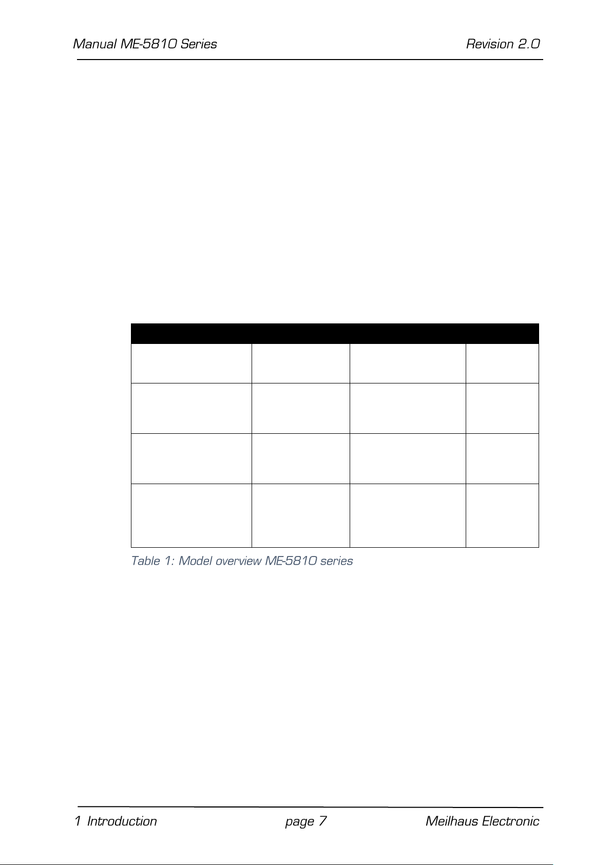
Model
Opto-Dio
Opto-FIO*
Counter
ME-5810A
1 x 16
bit DI
1 x 16
bit DO
4 FI channels
4 FO channels
3 x 16
bit
ME-5810A/S
...with streaming
operation
1 x 16
bit DI
1 x 16
bit DO
4 FI channels
4 FO channels
3 x 16
bit
ME-5810B**
(ME-5810A +
ME-5002)
2 x 16
bit DI
2 x 16
bit DO
4 + 4 FI channels
4 + 4 FO channels
3 x 16
bit
ME-5810B/S**
(ME-5810A/S with
streaming operation
+ ME-5002)
2 x 16
bit DI
2 x 16
bit DO
4 + 4 FI channels
4 + 4 FO channels
3 x 16
bit
1.3 Features
The ME-5810 series PC boards are opto-isolated digital-I/O boards
with bit-pattern detection and counters for PCI-Express- and CompactPCI-systems. In this user manual “ME-5810” is used for all
versions of the cards, whereas “ME-5810A” or “ME-5810B” is
used to describe special features of these versions.
If required, certain subdevices can alternatively be configured for
frequency measurement or for pulse generation (see chapter 4
from page 26). As an option, the base-board can be extended with
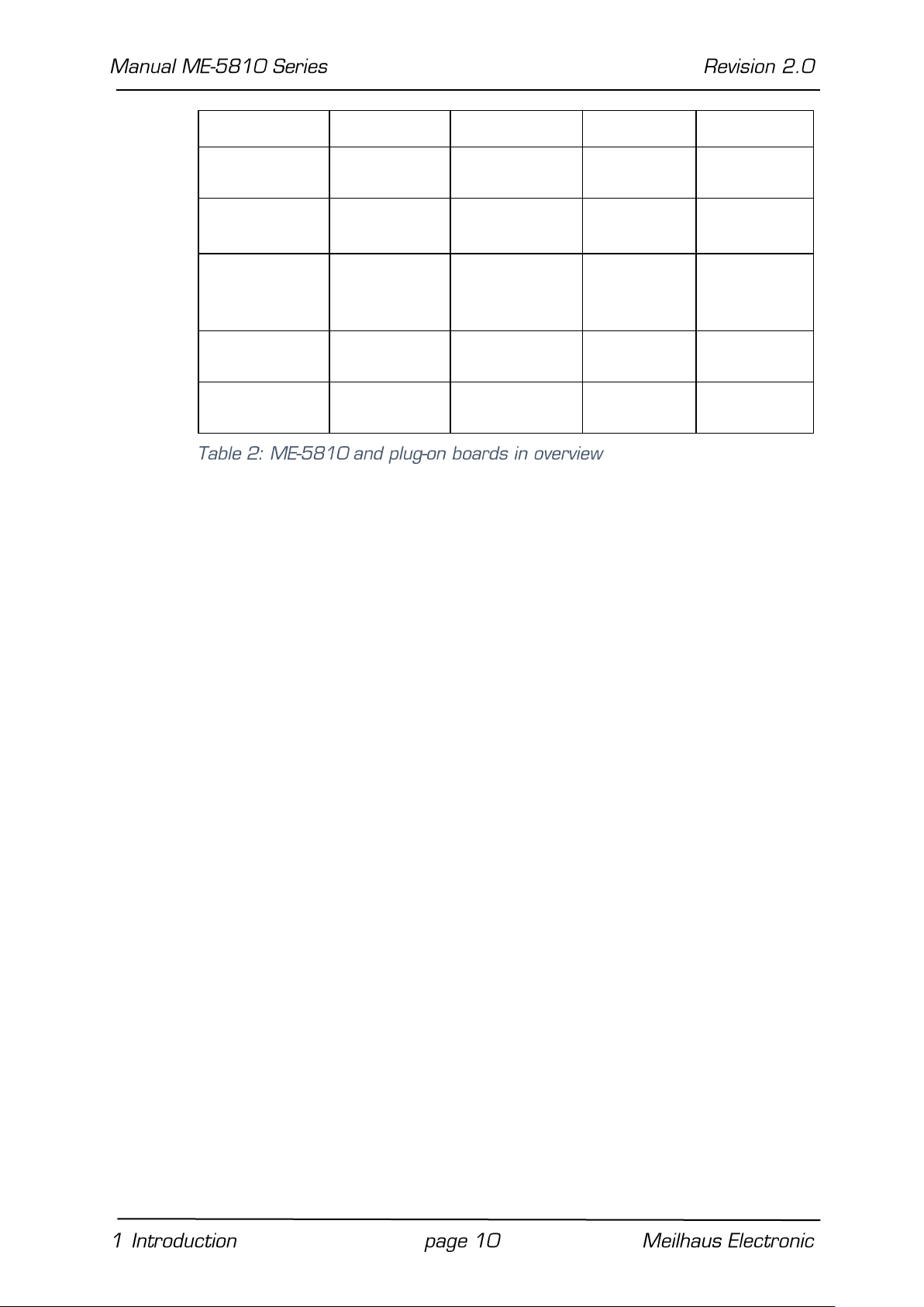
add-on boards (see table 2 on page 10).
Model overview:
* Alternative configuration can be selected with ME-iDC.
** ME-5810A(/S) is always registered in the Windows device manager.
Opto-isolated digital-inputs: The ME-5810 has 16 opto-iso-
lated inputs. Further 16 opto-isolated inputs can be added using the plug-on board ME-5002. The inputs run with a voltage
high level of 3…60 V (specifications see page 38).
Opto-isolated digital outputs: Die ME-5810 has 16 opto-iso-
lated outputs. Further 16 opto-isolated outputs can be added
using the plug-on board ME-5002. The source-driver can drive
up to 370 mA per pin (all 16 outputs active). The detailed specifications of the sink and/or source drivers can be found on page
38. The source drivers are short-circuit-proof and are equipped
Page 8

with a current limiting per channel. If required, the output
driver can send an interrupt on overload to the PC.
A suitable external source is required to supply the output drivers.
Frequency measurement: With the concept of “configurable
subdevices” the subdevice 0 can also be used as a frequency
counter. Four independent channels are available to measure
the frequency and duty cycle of periodic rectangular signals
(max. 5.5 MHz). 4 further channels can be added using the
plug-on board ME-5002.
Pulse generator: With the concept of “configurable subde-
vices” the subdevice 1 can also be used as a rectangular signal
generator. Four independent channels are available to output a
periodic rectangular signal up to 5.5 MHz with selectable duty
cycle. 4 further channels can be added using the plug-on board
ME-5002.
Sink/source selection: You can switch the output ports over
from sink to source drivers or high impedance by software for
an optimal adaption in industrial applications. “High impedance”
means that the voltage level at the output pin depends on your
external application.
Bit-pattern detection: If required, the bit-pattern at the digital
input port can be monitored. Depending on the mode an interrupt can be generated, if the bit-pattern changes or is
equal/not equal to a given bit-pattern. In streaming mode bitpattern detection can be used to control the input/output operation depending on the selected operating mode (no interrupt
operation).
The isolation voltage between the opto-isolated inputs/outputs
and PC-ground is 1 kVAC
RMS
.
The opto-isolated digital inputs of the ME-5810 and ME-5002
are equipped with an overvoltage protection diode that can discharge voltage pulses to ground for a short period of time.
Depending on your application you can select between these operating modes:
Single: In this mode a single value can be read or written under
software control (see chapter 4.1.1 on page 29).
Streaming (“S”-versions only): In this mode data I/O makes use
of the FIFO, either under timer control and/or controlled by external trigger signals. Various trigger options are available that
can be defined as start and stop conditions. Subdevice 0 is defined as a 16-bit input port and subdevice 1 as a 16-bit output
port (see chapter 2.1 on page 11).
Page 9
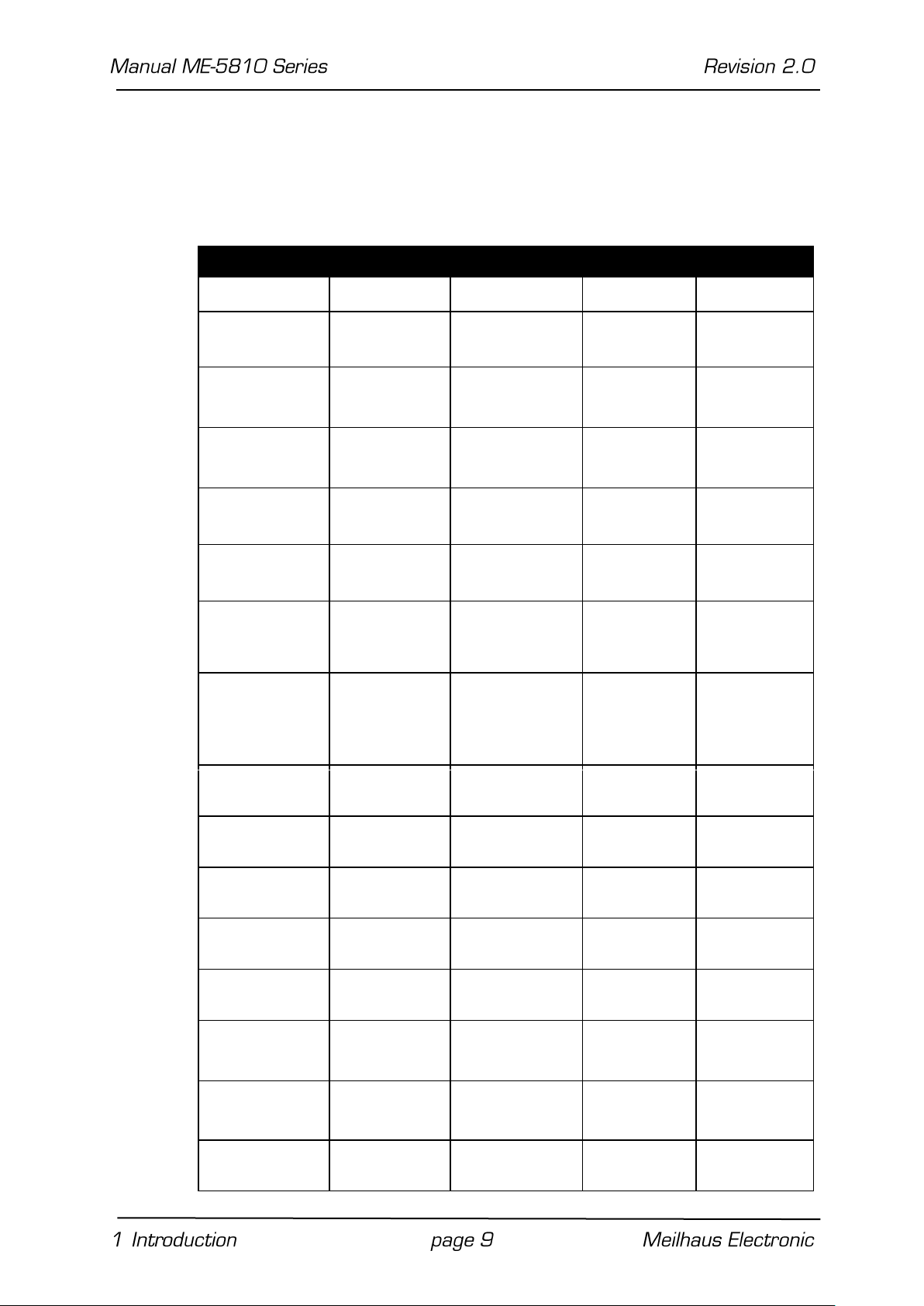
Model
ME-5810 A
ME-5001
ME-5002
ME-5004
PC-Interface
cPCI/PCIe
– – –
Board type
base board
plug-on board
plug-on
board
plug-on
board
DIO-channels
1 x 16-
bit
DI,
1 x 16-
bit DO
2 x 8-bit DIO+
4 x 8-bit
DIO**
1 x 16-
bit
DI,
1 x 16-b
it DO
1 x 16-
bit
DI,
1 x 16-
bit DO
Streaming
channels*
1 x 16-
bit
DI,
1 x
16-
bit DO
– – –
I/O rate
DI/DO
30 MS/s
/
30 MS/s
– – –
Frequency
FI/FO
300 kHz/
3 kHz
5.5 MHz/
5.5 MHz
300 kHz/
3 kHz
300 kHz/
3 kHz
Ext. trigger
for
streaming*
✔
– – –
Softwarestart/-stop
for
streaming*
✔
– – –
Frequency
measurement
4 channels
4 channels
4 channels
4 channels
Pulse
generator
4 channels
4 channels
4 channels
4 channels
Counter
(8254)
3 x 16
bit
– – –
Bit-pattern
change
✔ – ✔
✔
Bit-pattern
compare
✔ – ✔
✔
DI/FI level
3…60 V
3.3 V/5 V
(4 x 8 bit***)
3…60 V
3…60 V
DO/FO level
15…30 V
3.3 V/5 V
(4 x 8 bit***)
15…30 V
15…30 V
Active
termination
– 4 x 8
bit***
–
–
Interrupt: Used for interrupt processing in bit-pattern change
and bit-pattern compare mode (see chapter 4.3 on page 35).
Custom specific firmware versions are available on request.
Page 10
Opto-isolation
✔ – ✔
✔
Sink/Source
selection
✔ – ✔
✔
Temperature
monitoring
source driver
–
source
driver
source driver
Field wiring
78-pin D-Sub
female
socket
25-pin D-Sub
female socket
via 78-pin
D-Sub of
base board
37-pin D-Sub
female
socket
Configurable
firmware
✔ ✔ ✔
✔
Configurable
subdevices
✔ ✔ ✔
✔
* Streaming mode only for “S”-versions
** opt. via ME-AK-D25F/S (cPCI)
*** only for subdevice 0…3.
1.4 System Requirements
The ME-series may be installed into any PC (Intel® Pentium® processor) with a free standard PCI-, PCI-Express- resp. CompactPCIslot (32 bit, 33 MHz, 5 V). The board is supported by the Meilhaus
Electronic Intelligent Driver System (ME-iDS).
1.5 Software Support
The ME-series is supported by the Meilhaus Electronic Intelligent
Driver System (ME-iDS). The ME-iDS is a unique driver system covering different devices and operating systems. It supports Windows 2000/XP/Vista and Windows 7, 8.1, 10 and contains a universal function library (API) for all common programming languages.
A detailed description of the functions can be found in the ME-iDS
manual on the CD/DVD enclosed.
Please also note the corresponding README-files.
Page 11
2 Initial Operation
Please read your computer’s instruction manual on how to install
new hardware components before installing the board.
2.1 Software Installation
Installation under Windows
The following basic procedure should be used:
If you have received the driver software as an archive file, please
unpack the software before installing the board. First choose a directory on your computer (e.g. C:\Temp\Meilhaus\ME-iDS).
Use the Meilhaus Electronic Intelligent Driver System (ME-iDS) for
programming your new data acquisition hardware. For installation
and operation of the driver system, please follow the documentation in electronic form included with the software package.
2.2 Test Program
For simple testing of the board use the corresponding test program provided with the ME-iDS.
ME-PowerLab3. Run the program from the Windows Start menu.
This will allow you to text all the important functions of the hardware.
You will find simple test programs in the SDK of the ME-iDS, in
the “Test Executables32” or “Test Executables64” subfolders.
2.3 Fitting the Plug-on Boards
The boards should be handled with care in order to make sure that
the device is not damaged by electrostatic discharge (ESD), mechanical stress or unsuitable current surges. Precautions should
also be taken to avoid an electric shock. Ensure that standard ESD
safety precautions are taken. At least one hand should be
grounded in order to dissipate any electrostatic charge.
Observe the following procedure:
Page 12

1. If the base board is installed, you must first remove it in or-
der to be able to insert the plug-on board. Here you should
observe the procedure as described in the manual for your
PC system.
2. Make sure that electrostatic discharges cannot take place
through the plug-on board or the base board as you plug it
in. Follow the standard ESD safety precautions.
3. Push the plug-on board carefully, and with only a little force,
on to the male connector provided for it (see picture 1,
items 1, 2 and 3). Check that the board is fully plugged in.
4. Choose two adjacent slots for the installation. If necessary,
remove an additional blanking plate for the slot of the plug-on
board.
5. Carefully plug the combination of the base and plug-on board
into the computer.
6. Screw the two slot brackets down firmly.
7. Close the PC system again.
Page 13
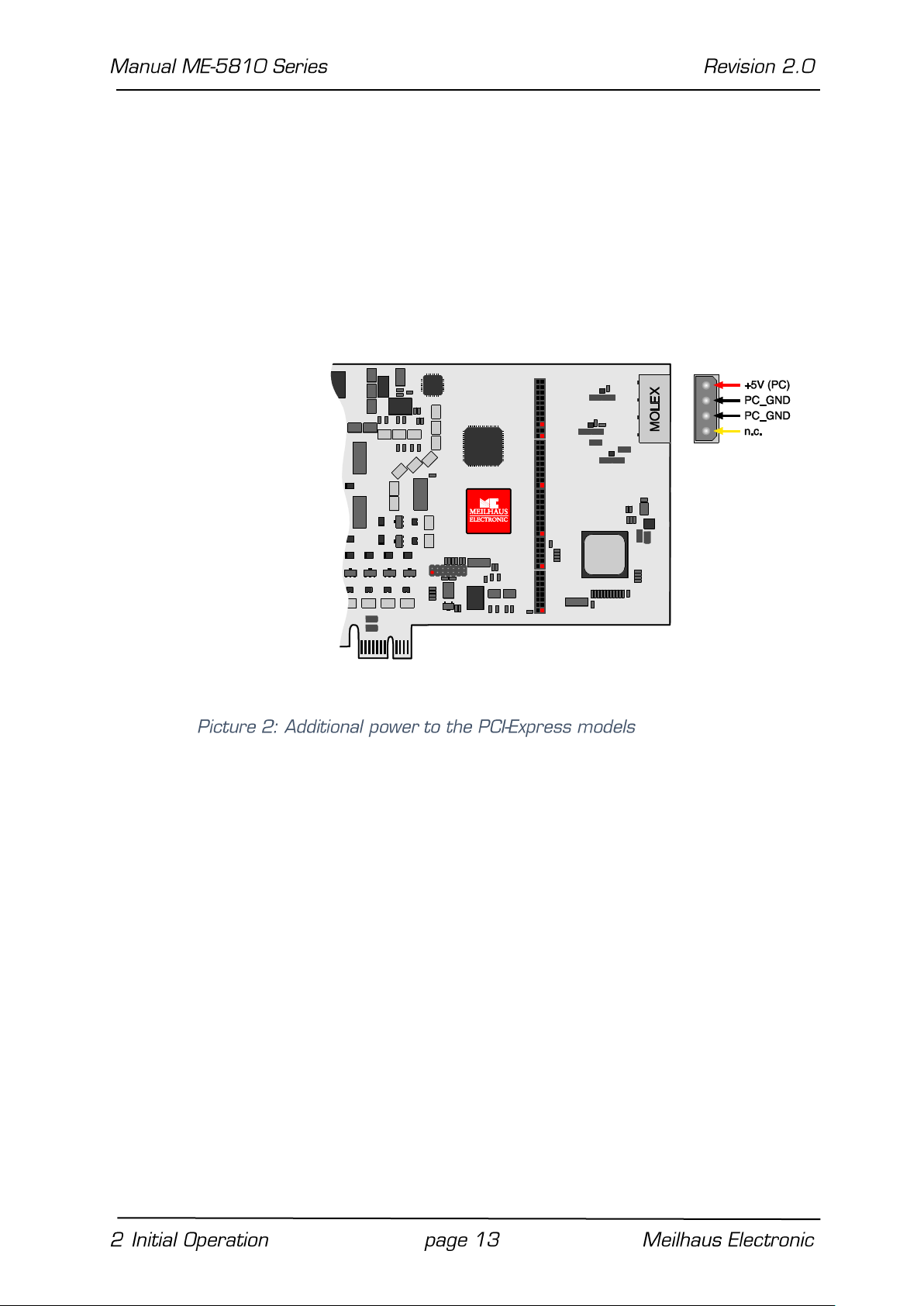
2.4 Power Supply for PCI-Express Models
Because of the PCI-Express slot drive’s insufficient current for op-
erating the board, an additional supply is required via the PC power
supply. For that purpose connect a free “MOLEX” connector of the
PC (as used for power supply of drives) with the appropriate terminal of the board (see the following diagram).
Otherwise the board may be irreversibly damaged!
Page 14
3 Hardware
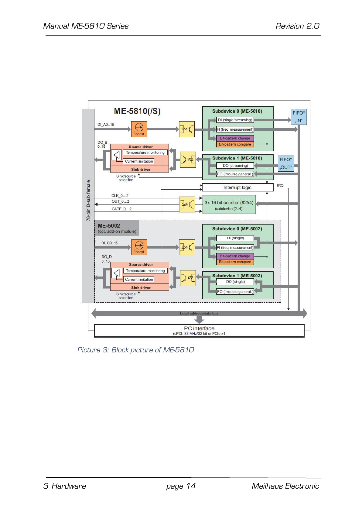
3.1 Block Picture
*Note: “FIFO IN” and “FIFO OUT” for streaming mode are only avail-
able on “S”-versions.
Pinout picture of the 78-pin D-sub female connector in the appendix (see “Pinout”page 46).
In the following chapters you will learn more about the external wiring of the functional sections. Chapter 4 from page 26 describes
the operation modes and the programming.
Page 15
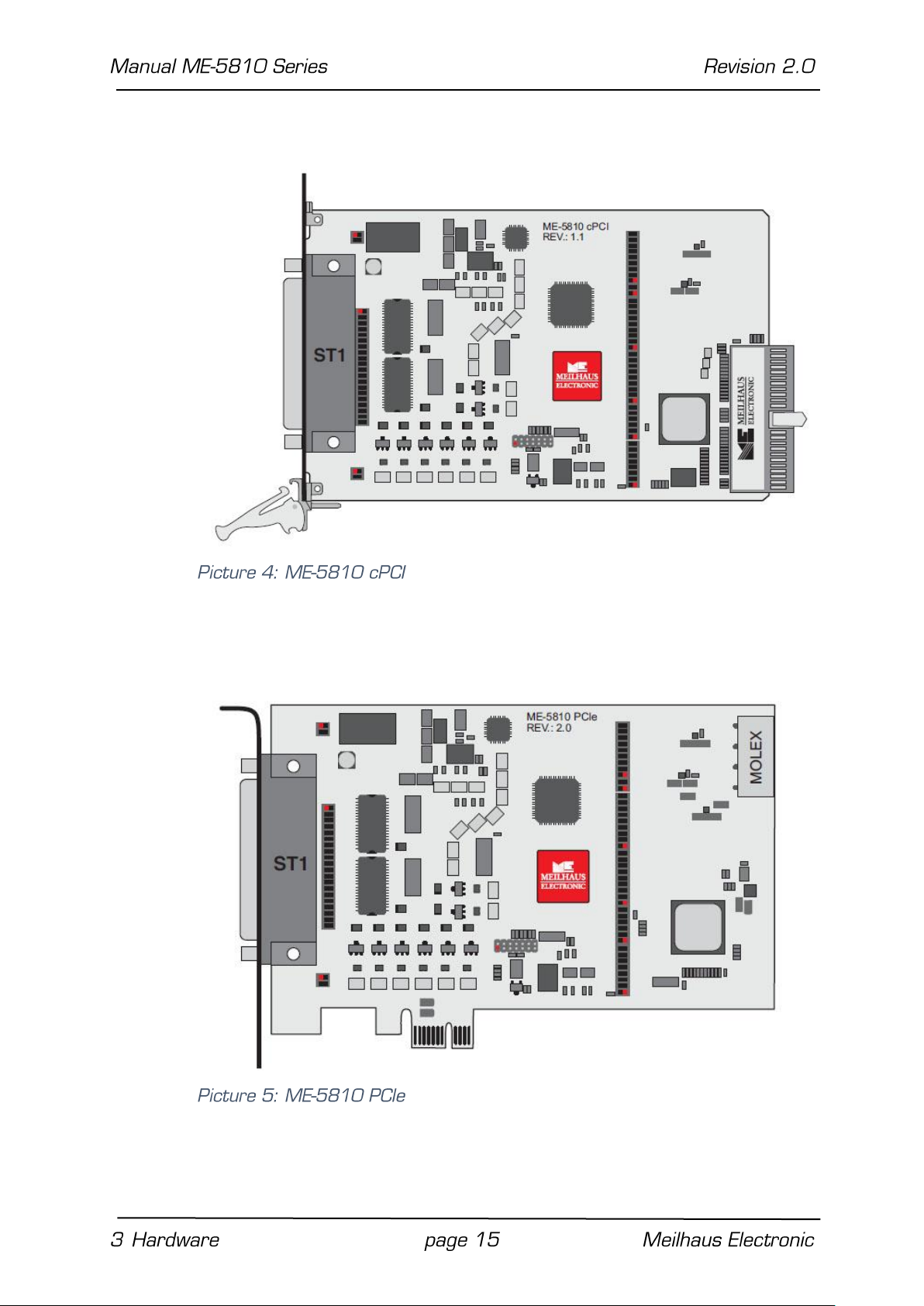
3.2 ME-5810 cPCI
3.3 ME-5810 PCIe
Page 16

3.4 ME-5002
3.5 Digital Input/Output
The ME-5810 series opto-isolated ports have been designed for
applications in industrial control applications (typ. 24 V). An external power supply (pin: VCC_EXT) is required for the opto-isolated
digital-I/O section. Depending on the application, the drivers of the
output ports can be configured as sink or source or high impedance
via software. The isolation voltage to PC-ground is 1000 VAC
The ME-5810 series base board has 16 opto-isolated inputs (port
A) and 16 opto-isolated outputs (port B). In combination with the
plug-on board ME-5002, 16 further opto-isolated inputs (port C)
and 16 opto-isolated outputs (port D) can be added. Due to the
opto-isolation, the port direction is fixed.
RMS
.
In streaming mode ports A and B share the bandwidth for the data
transfer between boards on PC. The bandwidth depends on the
Page 17

configuration of your PC – a total data throughput of up to
30 MS/s is realistic (see also table 6).
The programming of the various operating modes is described in
chapter 4.1 from page 28.
3.5.1 Opto-Isolated Inputs
The ME-5810 has 16 opto-isolated inputs (port A). In combination
with a plug-on board ME-5002, 16 further opto-isolated inputs
(port C) can be added.
The inputs have been designed for an input high-level U
in,H
=
3…60 V. A reference to the ground of the external circuitry via
GND_EXT (pins 9, 11, 59) has to be setup in any case. The input
lines show logic “0” if not connected.
The opto-isolated digital-inputs of the ME-5810 and ME-5002 are
protected from over-voltages with special Z-diodes, so called Transient Voltage Suppressor diodes (TVS diodes). These diodes can
discharge short voltage pulses with U
(Reverse Working Maxi-
RWM
mum) greater than 64.4 V to ground (max. 600 W pulse power at
a pulse width of 1 ms).
Page 18

3.5.2 Opto-Isolated Outputs
The ME-5810 has 16 opto-isolated outputs (port B). In combination with a plug-on board ME-5002, further 16 opto-isolated outputs (port D) can be added.
The ME-5810 and ME-5002 output ports are equipped with special
driver chips that allow a selection of sink and source via software.
Depending on the application, the user can switch between low-active outputs (sink driver = standard setting) and high-active outputs (source driver) via software. Moreover, the output ports can
be set to high impedance. A reference to the ground of the external wiring via GND_EXT (pins 9, 11, 59) has to be setup in any
case.
3.5.2.1 Sink Driver
Each output is equipped with two sink driver chips of type
ULN2803, detailed specifications see page 38.
The maximum current per output (IC = I
) depends on the satura-
Sink
tion voltage UCE and is limited by the power loss of the sum of the
channels on P
= 1 W per chip (DO_x 0…7 = chip 1, DO_x 8…15
tot
= chip 2), see picture 9 and 10.
P
= P0 + … + P7 ≤ 1 W (per chip bei 70 ºC)
tot
with P0 = I
C0
⋅ U
CE0
Page 19

To supply the sink output drivers, an external power supply has to
be connected to VCC_EXT (Pin 10, 20) with sufficient power (depending on the application). At full load this means min. 0.8 A for
the ME-5810A and min. 1.6 A for the ME-5810B.
Page 20

Number Of Channels Used
1
16
32
I
OUT
[A]
0.625 A
0.370 A
0.180 A
3.5.2.2 Source Driver
Each input port is equipped with two source driver chips of type
ISO1H811G; detailed specifications see page 38.
The source output drivers are short-circuit-proof and are equipped
with a current limiting per channel. The combination of current limiting, thermal shutdown, and automatic restart protects the circuitry against overload.
In the case of an overload condition (T
= typ. 175 °C) the related
TSD
channel will switch off and on again automatically, as soon as the
junction temperature has fallen below the threshold of TR =
135 ºC. If a chip temperature of typ. 130 ºC is still exceeded, the
overloaded channel remains disabled and is only reactivated, if the
temperature decreases below TCR = 110 ºC. Channels in standard
(no overload) condition can be used at any time without restrictions. In the case of an overload condition the output driver
(per port) can send an interrupt to the PC. A further security feature is a complete disabling of a port in case of a missing ground
connection.
The following table shows the maximum output current I
pendency of the number of channels in use.
in de-
Out
Page 21

To supply the source output drivers, an external power source has
to be connected to VCC_EXT (pin 10, 20), with sufficient power
(depending on the application). At full load this means minimum 6 A
for the ME-5810A/B. The output voltage U
can be calculated
Out,H
like this:
U
out, H
= U
– (RON ⋅ I
ext
out
)
3.5.3 External Trigger
3.5.3.1 External Trigger Inputs
Each digital input can be used as a trigger input. The trigger conditions for start and stop of an I/O under timer control (streaming
mode operation on “S”-versions) can be configured in a very flexible
way. Also see picture 12 on page 21 as well as picture 19 on page
35.
Note: In single mode operation I/O cannot be triggered externally.
See chapter 4.3 on page 35.
3.5.3.2 Edge Detection
Any digital input can be configured to start an operation on a rising, a falling or any edge (i.e. both rising/falling edge).
3.6 Frequency Input/Output
With the concept of “configurable subdevices” on the ME-5000 series boards you can use certain subdevices with an alternative
functionality. The configuration tool ME-iDC is used to change the
configuration before the user application is started.
The following channels are available:
Page 22

Frequency measurement (FI = “Frequency Input”):
4 independent inputs for measurement of frequency and duty
cycle of periodic rectangular signals (max. 300 kHz). 4 further
channels can be added using the plug-on board ME-5002.
Pulse generator (FO = “Frequency Output”):
4 independent outputs for a periodic rectangular signal up to
3 kHz with a selectable duty cycle. 4 further channels can be
added using the plug-on board ME-5002.
The related pins are marked with FI_x and FO_x in the pinout picture on page 24. The remaining I/O-channels of the digital-ports
cannot be used in this configuration.
Note: For the configuration “pulse generator” (FO) take care of the
level at the unused pins DO_B4..15 (ME-5810) and DO_D4..15
(ME-5002). When used as sink drivers the channels are high impedance, when used as source drivers they are connected to
ground!
The specifications of the digital-I/O ports also apply to the FI/FO
lines. A reference to the ground of the external circuitry via
GND_EXT (pins 9, 11, 59) has to be setup in any case.
The frequency counters and pulse generators are configured via
software. Chapter 4.1 on page 28 describes the programming of
the frequency-I/Os.
3.7 Counters
A standard counter chip of type 82C54 is used on the ME-5810
series boards. This versatile chip has 3 independent 16-bit (downward) counters. All counter signals are available at the D-sub female connector.
With a suitable enabling of the GATE input (0 V) the related counter will start downward-counting with negative edge control. The
counter clock (CLK) has to be supplied externally and can be
max.10 MHz. With a suitable external wiring the counters also can
be cascaded.
All counter signals (CLK, GATE, and OUT) are opto-isolated. The
counter inputs have been designed for 24 V (Rv = 3 kΩ ) as used in
industrial control applications. When the counters are used, U
ext
Page 23

has to be in the range of 24…30 V. The counter outputs are
equipped with pull-up resistors (RUP = 4.7 kΩ ).
For programming the timers see chapter 4.1 on page 28.
3.7.1 Wiring of the Counters
Notes:
Output OUT_2 is designed as an “Open Collector” output, i.e.
as soon as the output is conducting (logic “1”), the load RL is
connected to ground (GND_EXT). Logic “0” means that the out-
put is in a high-impedance state.
The polarity of the input signals (CLK_x and GATE_x) is inverted
by the opto-couplers.
All counter signals require a reference to external ground
GND_EXT (pins 9, 11, 59).
The inputs CLK_x and GATE_x have been designed for a voltage
level of +24 V (Rv = 3 kΩ ).Note for IF: 7.5 mA ≤ IF ≤ 10 mA.
The max. output current of opto-isolated versions may not ex-
ceed I
= 30 mA.
Out
Page 24

f
OUT_2 =
Base clock
(
with <Prescaler> = 2…(216– 1
))
<Prescaler> ⋅100
3.7.2 Pulse Width Modulation
Pulse width modulation (PWM) is a special application of the counters. With a suitable external wiring a signal with variable duty cycle can be generated with the help of counters 0…2. The duty cycle can be varied in the range of 1…99 % in steps of 1.
The prescaler has to be sourced with an external base clock of
max. 10 MHz. This results in a max. output signal frequency of
50 kHz. Picture 14 shows the external wiring to be used with the
functions (see also ME-iDS manual).
The following picture shows the external wiring of the counters for
the ME-5810.
For programming the PWM output please read the ME-iDS user
manual and the ME-iDS help file (see ME-iDS Control Center).
Page 25

3.8 External Interrupt
If required, you can also monitor the bit-pattern of a digital input
port. You can select one of the modes “bit-pattern change” and
“bit-pattern compare”. As soon as the specified event occurs, an
interrupt is issued and passed directly to the PC.
The digital inputs/outputs are programmed in the single operating
mode. The interrupt handling is carried out with the … func-
tions; see also chapter 4.3 on page 35.
Page 26

4 Programming
For programming the device please use the Meilhaus Electronic Intelligent Driver System (ME-iDS) included in your package. The MEiDS is a unique driver system covering different devices and operating systems. It supports Windows 2000 and higher and contains a
universal function library (API) for all common programming languages (the extent of the current software support can be found in
the README-files of the ME-iDS).
A detailed description of the functions can be found in the ME-iDS
manual (see CD/DVD enclosed or online:
www.meilhaus.de/download/ME-iDS.
Further details regarding the assignment of the subdevices and device specific arguments can be found in the help file (help file format
under Windows, *.chm) which can be accessed via the „ME-iDS
Control Center“ in the info area of the task bar (as a rule in the
lower right corner of the screen) or via the Windows start menu.
The ME-5810 series base boards are devices with five subdevices,
beginning with index “0”. When using plug-on boards (e.g. ME-
5002) these appear as individual devices and subdevices, beginning
with the index “0”. The functionality of the subdevices can be se-
lected by the user from a list of predefined configurations. The desired configuration has to be selected with the configuration tool
ME-iDC before the user application is started. With the standard
configuration (ID 0) the board is ready to-use at once. The following
tables show an overview of the configurations available:
Page 27

Subdevice of Type
…Subtype
I/Os
ID of the
Configuration
Subdevice 0 (DI, FI)
Digital input (DI)
(ME-5810A)
single
16-bit port
0*
Digital input (DI)
(ME-5810A/S)
streaming
16-bit port
0*
Frequency input (FI)
single
4 channels
1
Subdevice 1 (DO, FO)
Digital output (DI)
(ME-5810A)
single
16-bit port
0*
Digital output (DI)
(ME-5810A/S)
streaming
16-bit port
0*
Frequency output (FI)
single
4 channels
1
Subdevice 2…4 (Counters, Type 8254)
3 x Counter (CTR)
single
3 x 16
bit
0*
Subdevice of Type
…Subtype
I/Os
ID of the
Configuration
Subdevice 0 (DI, FI)
Digital input (DI)
single
16-bit port
0*
Frequency input (FI)
single
4 channels
1
Subdevice 1 (DO, FO)
Digital output (DO)
single
16-bit port
0*
Frequency output (FO)
single
4 channels
1
Base boards ME-5810A(/S)
Plug-on board ME-5002 (included with ME-5810B(/S))
*Standard configuration at shipment. The most recently selected configuration in the ME-iDC is stored in a non-volatile memory on the board,
and is automatically loaded after a restart.
Depending on your application you can choose one of the following
operating modes:
Page 28

Operating Mode
Speed
Trigger
Single
Single value
Input/output by
software
Stream-timer …with
option "wraparound”
f
Input signal
: to 300 kHz
f
Output signal
: to 3 kHz
Start/stop per
software or ext.
trigger
Stream-trigger-sample
f
Input signal
: to 300 kHz
f
Output signal
: to 3 kHz
Start/stop per
software or ext.
trigger
Interrupt
(Bit-pattern detection)
f
IRQmax
. = 10 kHz
Ext. trigger signal
at a digital-I/O port
Single: In this mode single values can be read or written.
Streaming (only for the versions “S”): In this mode data-I/O is
done via FIFO. The timing can either be controlled by a timer
and/or external trigger signals. Various trigger options are
available which can be defined as start and stop conditions, see
chapter 4.2.1 on page 33.
Interrupt: For interrupt processing in the modes bit-pattern
change and bit-pattern compare (see chapter 4.3.1 from page
36).
Detailed timing pictures can be found in the ME-iDS manual.
4.1 Single Operation Mode
Individual values can be read or written in this operating mode.
Notes:
The digital-I/O channels direction is determined by the ME-5810
series hardware (opto-couplers).
In power-down state and after switching on the PC all outputs
are in a high-impedance state. Only if “1” is written, the output
changes to conductive.
A port that is configured as an output can also be read back!
Page 29

ME-5810
ME-5001
ME-5002
ME-5004
✔ ✔ ✔
✔
ME-5810
ME-5001
ME-5002
ME-5004
✔ ✔ ✔
✔
4.1.1 Digital Input/Output
For input/output of individual digital values the single operation
mode is used. The subdevices are defined as follows: subdevice 0 of
the ME-5810 always is of type ME_TYPE_DI and subdevice 1 of
type ME_TYPE_DO. The subtype of the subdevice is ME_SUBTYPE_
STREAMING for the ME-5810/S, otherwise ME_SUBTYPE_ SINGLE.
If the plug-on board ME-5002 is used, its subdevice 0 is of type
ME_TYPE_DI and subdevice 1 of type ME_TYPE_DO.
Please observe the ME-iDS manual and the ME-iDS help file (*.chm)
for the procedure. You can open both these documents through
the “ME-iDS Control Center) or through the Windows Start menu.
Please read chapter 3.5 on page 16 for the wiring of the digital
ports.
4.1.2 Frequency Input/Output
Before you can use the "Frequency measurement" or "Pulse generator" modes, it is necessary, before opening your application, to run
Page 30

the ME-iDC configuration tool in order to specify the configuration
for the corresponding subdevice (see also Table 4 on page 27).
The programming of the frequency measurement and the pulse
generator is always done in the single operation mode. The subtype
of the subdevices is always ME_SUBTYPE_SINGLE.
Please read the ME-iDS manual and the ME-iDS help file (*.chm)
carefully prior to programming. You can open both of these docu-
ments through the "ME-iDS Control Center" or through the Windows Start menu.
Two variables are introduced to describe the rectangular signal,
and apply equally to input and output. One value indicates the period T, while the other value provides the duration of the pulse of
the first phase of the period t1P. For frequency measurement, the
measurement starts with the first rising edge, and finishes with
the next rising edge. The falling edge that lies between them defines the end of the first phase. In pulse generator mode, output
normally starts with a high level, changing to the low level when the
first phase has elapsed.
Page 31

The time reference is provided by a 66 MHz counter. It is configured using the function. A period of 15.15 ns follows from this, and is defined as the smallest unit of time. It is referred to below as "1 tick". The resolution for T and t1P is therefore
1 tick (see also the specifications on page 38).
Note that the value of the maximum period T
duty cycle. A distinction is drawn between rectangular signals with
an asymmetrical duty cycle T
T
max. sym
.
The figures for the ME-5810 are:
T
max. asym.
= 16.25 s (0.06 Hz); T
The wiring of the frequency inputs/outputs can be found in chapter
3.6 on page 21.
4.1.2.1 Frequency Measurement
With the frequency measurement operating mode (FI= "Frequency
In-put") you can determine the period or frequency, and the duty
cycle of rectangular signals up to 300 kHz. The resolution is 1 tick
= 15.15 ns. The measurement always starts at a rising edge. On
the ME-5810, all 4 frequency measuring channels (FI_A0…3) are
addressed as subdevices of type ME_TYPE_FI, subtype ME_SUBTYPE_SINGLE. Each channel can be programmed independently.
max. asym
. depends on the
max
. and a symmetrical duty cycle
max. sym.
= 32.5 s (0.03 Hz)
In combination with the plug-on board ME-5002, 4 additional frequency measurement channels (FI_C0…3) are available which can
be addressed as one subdevice.
Note: If the frequency and duty cycle are the magnitudes you want,
these can easily be calculated from the values returned for
<pdTime>. The formula is:
Frequency [Hz] = 1/period [s]
Duty cycle [%] = („duration of the first phase of the period“[s]/ pe-
riod [s] x 100
4.1.2.2 Pulse Generator
In the pulse generator operating mode (FO = "Frequency Output")
you can output rectangular signals with a variable duty cycle at frequencies of up to 3 kHz and with a resolution of 1 tick. On the ME-
5810, all 4 pulse generator channels (FO_B0…3) are addressed as
subdevices of type ME_TYPE_FO, subtype ME_SUBTYPE_SINGLE.
Each channel can be programmed independently.
Page 32

ME-5810
ME-5001
ME-5002
ME-5004
✔
– – –
The first phase of the rectangular signal is "high" by default. By setting the ME_IO_SINGLE_TYPE_FO_START_LOW flag it is also possible to start the output with a "low" level.
In combination with the plug-on board ME-5002, 4 additional pulse
generators (FO_D0…3) are available, addressed as one subdevice.
Note: An output channel can also be read back!
4.1.3 Counters (8254)
The programming of the counters is done in operation mode „Single“. A counter device of type 82C54 provides three 16-bit coun-
ters. Each counter is accessed as a subdevice of type
ME_TYPE_CTR, subtype ME_SUBTYPE_CTR_8254. Note the order
of operation as described in the ME-iDS manual and in the ME-iDS
help file (see ME-iDS Control Center).
4.1.3.1 Standard Operation Modes
The counters can be configured independently of one another by the
function for the following 6 operation modes (a
detailed description of the modes can be found in the ME-iDS manual):
Mode 0: Change state at zero
Mode 1: Retriggerable „One Shot“
Mode 2: Asymmetric divider
Mode 3: Symmetric divider
Mode 4: Counter start by software trigger
Mode 5: Counter start by hardware trigger
Please read picture 13 on page 23 for the wiring of the opto-isolated counter signals.
Page 33

ME-5810
ME-5001
ME-5002
ME-5004
“S”-version
– – –
4.1.3.2 Pulse Width Modulation
With the wiring shown in picture 14 on page 24 you can simplify
programming considerably using the functions
for this operation mode (see also ME-iDS manual
and ME-iDS help file).
4.2 Streaming Operation Mode
4.2.1 Digital Input/Output
The programming of the timer controlled input/output via FIFO is
carried out in the streaming operating modes. Port A is defined as
16-bit input port (subdevice 0 of type ME_TYPE_DI) and port B as
16-bit output port (subdevice 1 of type ME_TYPE_DO), each of subtype ME_SUBTYPE_STREAMING (only for versions “S”).
Please observe the ME-iDS manual and the ME-iDS help file (*.chm)
for the procedure. You can open both of these documents through
the "ME-iDS Control Center" or through the Windows Start menu.
4.2.1.1 Stream Timer
In this operating mode the values are acquired or output under the
control of a timer. A continuous transfer bandwidth between the
PC and the ME-5810 of up to 30 MHz is available, shared among
port A and B. You can sample a rectangular signal up to 300 kHz
with up to 100 times oversampling. An output rate of up to 3 kHz
is possible.
4.2.1.2 Stream Trigger Sample
In this operating mode individual values can be acquired or output
under the control of one or more external trigger signals. A continuous transfer bandwidth between the PC and the ME-5810 of up
to 30 MHz is available, shared among port A and B. You can sample a rectangular signal up to 300 kHz with up to 100 times oversampling. An output rate of up to 3 kHz is possible.
4.2.1.3 Wraparound Mode
Page 34

This option is used for repetitive output of the very same data
buffer on port B.
Note: When no more than 8192 values are to be output for an indefinitely long period, this is done on firmware level of the ME-5810
without loading the host computer.
4.2.1.4 External Trigger
On the „S“-versions the trigger conditions for starting and stopping the streaming operation mode can be selected very flexibly. It
is thus possible to enable one or more trigger inputs individually,
with specification of the desired trigger edge (rising, falling, or
any). All the enabled trigger inputs are logically ORed together. This
means that the first edge to arrive that meets the trigger condition starts or stops the input/output operation, according to the
selected operation mode (stream timer or stream trigger sample).
In other words, any change of the bit-pattern can be used as a
trigger event for the subdevice concerned.
For subdevice 0 all inputs of port A (DI_Ax) can be used and for
subdevice 1 all outputs of port B (DO_Bx) can be used, as they can
be read back (see picture 19).
Page 35

ME-5810
ME-5001
ME-5002
ME-5004
✔ ✔ ✔
✔
Note: “FIFO IN” and “FIFO OUT” only available on “S”-versions.
4.3 Interrupt Operation
On the board of the ME-5810 series you can monitor the bit-pattern of the 16-bit-wide input ports of subdevice 0 of the baseboard ME-5810 (DI_A0..15) as well as subdevice 0 of the plug-on
board ME-5002 (DI_C0..15). Depending on the application you can
select one of the operating modes “bit-pattern compare” and “bitpattern change”. As soon as the first edge that meets the trigger
condition arrives, an interrupt is issued and passed directly to the
PC.
Page 36

Programming the digital input/output is carried out in the operation
mode single. The subdevice must have the type ME_TYPE_DI. The
interrupt processing is controlled with the functions …
Please observe the ME-iDS manual and the ME-iDS help file (*.chm)
for the procedure. You can open both of these documents through
the “ME-iDS Control Center” or through the Windows Start menu.
4.3.1 Bit-Pattern Change
In the bit-pattern change mode, one or more bits that are to be
monito- red for a change of state can be defined (masked). A 32bit-wide argument per subdevice contains the mask. For each input
pin both one bit for rising edge and one bit for falling edge is available. If the state of at least one bit masked with a "1" changes (0 →
1 or 1 → 0), an interrupt is issued (see picture 21 on page 36).
In what is known as the "extended format" of interrupt handling
(see the ME-iDS manual), two bits are available for the interrupt
status of each pin. One is for the rising edge, and one for the falling edge. The bits for the falling edges are assigned to the bit
b 15…0, while the bits for the rising edges are assigned to the
bits b 31…16.
Page 37

Example (see picture 21):
By writing the value 0x00800004 Hex as a mask value (see parameter <iIrqArg> of the function , bit 2 is monitored
for a falling edge, and bit 7 for a rising edge. A rising edge now is
to arrive at bit 7, so that an interrupt is issued and in the interrupt status value bit b 23 returns "1". Any edges that might arrive
at pins labelled with an "X" are ignored. Only the change in state of
a pin whose edge is set to "1" in the parameter <iIrqArg> can issue an interrupt.
The interrupt event is evaluated with the function
We recommend using what is known as the "extended format" to
obtain detailed information about the triggering edge.
4.3.2 Bit-Pattern Compare
In the “bit-pattern compare” mode, the bit-pattern of digital inputs
can be monitored for equality or inequality. The compare bit-pattern of the corresponding subdevice is used as reference. If the
state changes from unequal to equal or from equal to unequal, an
interrupt is generated (see picture 22 on page 37).
Page 38

PC Interface
PCI-Express Bus
32 bit, 33 MHz, 3.3 V, PCI-Express x1 specification
version 2.0
CompactPCI Bus
32 bit, 33 MHz, 5 V, specification PICMG 2.0 R3.0
Plug&Play
is fully supported
Digital Input/Output (general)
Measured
Quantity/Criterion
Condition/Explanation
Value
Ports ME-5810
(base board)
subdevice 0
(Single/Streaming)
16-bit input port opto-
isolated
subdevice 1
(Single/Streaming)
16-bit output port optoisolated
Ports ME-5002
(plug-on board)
subdevice 0
(Single)
16-bit input port opto-
isolated
subdevice 1
(single)
16- bit output port opto-
isolated
Operation modes
single
software triggered
read/write
stream timer
timer controlled
read/write of values via
FIFO
stream trigger sample
timer controlled
read/write of values via
FIFO
interrupt
bit-pattern change,
bit-pattern compare
FIFO-size
FIFO_IN
8192 values (16-bit-wide)
FIFO_OUT
8192 values (16-bit-wide)
5 Appendix
A Specification
(Ambient temperature 25 °C)
Page 39

Transfer rate in
streaming mode
between ME-5810 and
PC
max. 25 MHz (cPCI) resp.
30 MHz (PCIe)
(system-dependent)
Frequency input
signal
symmetrical rectangular
signal
max. 300 kHz
Frequency output
signal
symmetrical rectangular
signal
max. 3 kHz
option „wraparound“
max. 3 kHz, without load
for the Host PCs
Timer
(CHAN-time)
input
30.30 ns…65 s
(2..FFFFFFFFHex
Ticks)
output
0.15 ms…65 s
(11000..FFFFFFFFHex Ticks)
Timer resolution
programmable
15.15 ns (1 Tick)
Ext. trigger inputs
ME-5810
DI_Ax, DO_Bx
Ext. trigger edges
Rising, falling, any
Input level
see the following tables
Isolation voltage
U
ISO
(f = 60
Hz, t = 60 s)
max
. 1000 VAC
rms
Reference ground
isolated from PC ground
GND_EXT
Opto-Isolated Inputs
Static values
Conditions: TA=25 °C
Measured Quantity
Test Criterion
MIN
Type
MAX
Unit
U
in,H
3
60
V
U
in,L
0
2.2
V
R
in
Uin=24 V
4.3
kΩ
I
in
Uin=24 V
5.5
6
mA
Limiting Values
Measured
Quantity /Criterion
Condition/Explanation
Value
URWM over-voltage
protection for inputs
max. 600 W pulse power at a pulse
width of 1 ms
64.4 V
Page 40

Opto-Isolated Outputs
Conditions: TA=25 °C
Output-drivers
sink
2 x ULN2803 (ME-5810A)
+ 2 x ULN2803 (ME-5002)
source
2 x ISO1H811G (ME-5810A)
+ 2 x ISO1H811G (ME-5002)
External supply
U
ext
15…30 V
U
Lmax
U
ext
Sink Driver (UDN2803)
Measured
Quantity
Test Criterion
MIN
Type
MAX
Unit
I
OUT =IC
(output
current)
per channel
50
mA
See also characteristics curves in picture 23
I
CEX
(output
leckage current)
UCE=
50 V, TA=
25 °C
UCE=
50 V, TA=
85 °C
50
100
μA
U
CE
(SAT)
(
(collector
emitter saturation
voltage)
I
OUT
=350 mA
I
OUT
=200 mA
I
OUT
=100 mA
1.3
1.1
0.9
1.6
1.3
1.1
V
IR
(clamp diode
reverse current)
UR=
50 V, TA=
25 °C
UR=
50 V
, TA=
85 °C
50
100
μA
UF (clamp diode
forward voltage)
IF=350 mA
2.0 V
ton
(switch-on
time)
R
L
=125 Ω
,
U
OUT
=50 V,
C
L
=15 pFina
0.1
1 μs
t
off
(switch-off
time)
R
L
=
125 Ω ,
U
OUT
=
50 V,
CL=
15 pF
0.2
1 μs
For further specifications see chapter sink driver resp. source
driver
Output current
The maximum current per output (IC) depends of the saturation
voltage UCE and is limited by the power dissipation of the sum of
the channels to P
P
TOT=P0
+…+P7 ≤
=1 W per chip:
tot
1 W (bei 70 °C)
Page 41

Source Driver (ISO1H811G)
(short-circuit proof with current limiting and temperature monitoring)
Voltage supply
Conditions: U
ext
=15…30 V, TJ=-25…+125 °C
Measured
Quantity
Test Criterion
MIN
Type
MAX
Unit
U
OUT
Uext
=24 V; 1 channel
with I
out
=0,625 A
23.8
V
I
OUT
/channel
1 channel
625
mA
16 channel
370
mA
32 channel (with ME-
5002)
180
mA
U
USD
(undervoltage
shutdown)
7 10.5
V
RON
(resistance if
output active)
I
OUT
=
0.5 A, TI=25 °C
I
OUT
=
0.5 A, TJ=125 °C
150
270
200
320
mΩ
mΩ
IS (current
consumption driver
chip)
8 channels active per
chip; without load
10
14
mA
I
L
(off)
(output
current in inactive
state)
U
in
=
U
OUT
=
0 V,
0 5 30
μA
Page 42

Switching Times
Measured
Quantity
Test Criterion
MIN
Type
MAX
Unit
ton (switch-on
time)
RL=47 Ω, to 90 % U
out
64
120
μs
t
off
(switch-off
time)
RL=47 Ω, to 10 % U
out
89
120
μs
dU
out
/dt
(on)
(slope on
switch-on)
RL=47 Ω, up 10…30 %
U
out
, U
ext
=15 V
1 2 V/ μs
dU
out
/dt
(off)
(slope
on switch-off)
RL=47 Ω, up 70…40 %
U
out
, U
ext
=15 V
1 2
V/ μs
Limiting Values
Measured
Quantity
Test Criterion
MIN
Type
MAX
Unit
T
CSD
(housing
switch-off
temperature)
125
130
135
°C
TCR (housing reset
temperature)
110
°C
T
TSD
(junction
switch-off
temperature)
150
175
200
°C
TR (junction reset
temperature)
135
1 °C
I
lim
(DC-short-
circuit current)
U
ext
= 24 V, RL=10 mΩ
1.1
A
Frequency Input/Output
Availability
alternative subdevice configuration via ME-iDC
Signal-form
rectangular
Frequency Measuring Channels
Measured
Quantity/Criterion
Condition/Explanation
Value
Reference ground
isolated from PC ground
GND_EXT
Number of
channels
ME-5810A (FI_A0…3)
4 inputs
(opto-isolated)
Page 43

ME-5002 (FI_C0…3)
4 inputs
(opto-isolated)
Input-level
see digital I/O
Input-current
see digital I/O
Period (T)
T
min
. =T
min.asym.=Tmin.sym
.
T
max.asym
T
max.sym
3.3 μs (300 kHz)
16.25 s (0.06 Hz)
32.5 s (0.03 Hz)
Duty-cycle
variable, depending on T
measurable in steps of
1 tick
Resolution
1 tick
15.15 ns
Accuracy
± 15.15 ns
Operating modes
single
Pulse Generator Channels
Measured
Quantity/Criterion
Condition/Explanation
Value
Reference ground
isolated from PC ground
GND_EXT
Number of
channels
ME-5810A (FI_A0…3)
4 outputs (opto-isolated)
ME-5002 (FI_C0…3)
4 outputs (opto-isolated)
Output level
sink or source driver
see digital I/O
Period (T)
T
min
. = T
min.asym.=Tmin.sym
.
T
max.asym
T
max.sym
0.3 ms (300 kHz)
16.25 s (0.06 Hz)
32.5 s (0.03 Hz)
Duty-cycle
variable, depending on T
to be set in steps of
1 tick
Resolution
1 tick
15.15 ns
Accuracy
± 15.15 ns
Operating modes
single
Counters
Number
3 x 16 bit (1 x 82C54)
Opto-isolation
yes (dimensioning of the I/O level for 24 V)
Counter-clock
up to 10 MHz by external source
Page 44

…with Opto-Isolation
Measured
Quantity/Criterion
Condition/Explanation
Value
Reference ground
isolated from PC
ground
GND_EXT
External supply for
opto-couplers
U
ext
24…30 V
Level for Counter Outputs (OUT_x)
Type
“Open Collector”
U
Lmax
U
ext
I
Out
max. 30 mA
Level for Counter Inputs CLK_x, Gate_x)
Logic level
inverted by optocouplers
low-active
IF
7.5 mA ≤ I
F
≤ 10 mA
UIL max. 0.8 V
UIH 24..30 V, max. U
ext
Interrupt
Measured
Quantity/Criterion
Condition/Explanation
Value
Interrupt sources
passed directly to
the PC
bit-pattern change
bit-pattern compare
General Data
Measured
Quantity/Criterion
Condition/Explanation
Value
Power supply
CompactPCI
+5 V (via PCI-Bus)
PCI-Express
+3.3 V (via PCIe-Bus),
+5 V (via Molex plug from
PC power supply unit)
Current
consumption
CompactPCI
0.8…1.2 A (full-load)
PCI-Express
0.8…1.2 A (full-load)
Board dimensions
(without slot
bracket and
connector)
ComactPCI
3 U CompactPCI board
PCI-Express
162 mm x 98 mm
Page 45

Connections
ST1
78-pin D-sub female socket
I/Os der ME-5002
via ST1 of base board
Operating
temperature
0 °C…70 °C
Storage
temperature
-40 °C…100 °C
Air humidity
20 %…55 %
(non-condensing)
Certification
CE
Page 46

Name
Function
DI_A0..15
digital inputs of ME-5810 (subdevice 0)
DO_B0..15
digital outputs of ME-5810 (subdevice 1)
DI_C0..15*
digital inputs of ME-5002 (subdevice 0)
DO_D0..15*-
digital inputs of ME-5002 (subdevice 1)
CLK_0..2
clock inputs for counters
GATE_0..2
gate inputs for counters (low-active)
OUT_0..2
Counter outputs (type "Open-Collector")
FI_A0..3
frequency measurement inputs of ME-5810
(subdevice 0, alternative configuration)
FO_B0..3
pulse generator outputs of ME-5810
(subdevice 1, alternative configuration)
FI_C0..3*
frequency measurement input of ME-5002
(subdevice 0, alternative configuration)
FO_D0..3*
pulse generator output of ME-5002
(subdevice 1, alternative configuration)
VCC_EXT
VCC input for ext. power supply of isolated
ports, U
ext
typ. 24 VDC
GND_EXT
reference ground for isolated ports
(isolated from PC ground)
B Pinout
Note: „ME-5810“ represents all models of the ME-5810 series.
Legend for pinouts:
Note: In the configuration “pulse generator” (FO) do not forget to
take care of the unused pins DO_B4..15 (ME-5810) and
DO_D4..15 (ME-5002). When used as sink drivers they are in highimpedance state, when used as source drivers they are connected
to ground!
*These signals are only available in combination with the plug-on board
ME-5002 (note: ME-5810B = ME-5810 + ME-5002)
Page 47

B1 78-pin D-Sub (ST1) — ME-5810
*These pins can only be used as frequency measurement inputs
(FI_x) resp. pulse generator outputs (FO_x) after appropriate configuration of the corresponding subdevice with the ME-iDC. The remaining pins of the digital ports cannot be used for digital-I/O.
Page 48

C Accessories
We recommend to use high-quality connector cables with singleshielded lines per channel.
For further accessories please refer to the current Meilhaus Electronic catalog and the internet:
www.meilhaus.de/en/pc-boards/accessories/
Page 49

D Technical Questions
D1 Hotline
Should you have questions or inquiries concerning your Meilhaus
device, please contact us:
Meilhaus Electronic GmbH
Repair & Service
Am Sonnenlicht 2
D-82239 Alling
Sales: Support:
Tel.: (08141) 52 71 – 0 Tel.: (08141) 52 71 – 188
Fax: (08141) 52 71 – 129 Fax: (08141) 52 71 – 169
eMail: sales@meilhaus.de eMail: support@meilhaus.de
Download-Server and Driver Update:
To download current driver versions for Meilhaus Electronic devices
as well as manuals in PDF format, please go to:
www.meilhaus.org/driver
Service Department with RMA Process:
In case you need to return a board for repair purposes, we strongly
ask you attach a detailed description of the error as well as information regarding your computer/system and the software used.
Please register online using our RMA process:
www.meilhaus.de/en/infos/service/rma.htm.
Page 50

E Index
A
Accessories 50
Appendix 40
Index 52
Initial Operation 12
Interrupt 30
Interrupt Operation 37
Introduction 5
B
Bit-Pattern Compare 39
Block Picture 16
C
Counters 24
D
Digital Input/Output 18, 31
E
External Interrupt 27
External Trigger 23
F
Features 7
Fitting the Plug-on Boards 13
Frequency measurement 24
H
M
ME-5002 18
ME-5810 cPCI 17
ME-5810 PCIe 17
Model overview 7
O
Opto-Isolated Inputs 19
P
Package Contents 6
Pinout 48
Power Supply 14
Programming 28
S
Single 30
Sink driver 20
Software Installation 12
Software Support 10
Specifications 40
Streaming 30
Streaming Operation Mode 35
System Requirements 10
Hardware 16
I
Important Notes 5
T
Technical Questions 51
Test Program 12
timer controlled 40
 Loading...