

Page 1
Meilhaus Electronic Manual
ME-5001 1.1E
Plug-on Board for ME-5000 series
with up to 48 Digital I/Os
(alternatively: Frequency Measurement and Pulse Generator)
Page 2

Imprint
ME-5001 Manual
Version 1.1E
Issued on: 29. April 2013
Meilhaus Electronic GmbH
Fischerstraße 2
D-82178 Puchheim/Munich
Germany
http://www.meilhaus.com
© Copyright 2013 Meilhaus Electronic GmbH
All rights reserved. No part of this publication may be reproduced or distributed in any
form whether photocopied, printed, put on microfilm or be stored in any electronic media
without the expressed written consent of Meilhaus Electronic GmbH.
Important note:
The information contained in this manual has been reviewed with great care and is believed
to be complete and accurate. Meilhaus Electronic assumes no responsibility for its use, any
infringements of patents or other rights of third parties which may result from use of this
manual or the product. Meilhaus Electronic assumes no responsibility for any problems or
damage which may result from errors or omissions. Specifications and instructions are
subject to change without notice.
Borland Delphi is a trademark of Borland International Inc.
Turbo/Borland C is a trademark of Borland International Inc.
Visual C++ and Visual Basic are trademarks of the Microsoft Corporation.
VEE Pro and VEE OneLab are trademarks of Agilent Technologies.
ME-VEC and ME-FoXX are trademarks of Meilhaus Electronic.
Other company names and product names found in the text of this manual are also
trademarks of the companies involved.
Page 3

Manual ME-5001 Rev. 1.1E
Meilhaus Electronic Page 3 Table of Contents
Table of Contents
1 Introduction...................................................................................................... 5
1.1 Important Notes .....................................................................................5
1.1.1 Intended Use ................................................................................5
1.1.2 Improper Use................................................................................ 6
1.1.3 Unforeseeable Misuse.................................................................... 6
1.2 Scope of Supply....................................................................................... 7
1.3 Features................................................................................................... 8
1.4 System Requirements.............................................................................. 9
1.5 Software Support ...................................................................................9
2 Initial Operation .............................................................................................11
2.1 Software Installation ............................................................................. 11
2.2 Test Program ........................................................................................ 11
2.3 Fitting the Plug-on Board .....................................................................12
3 Hardware ........................................................................................................15
3.1 Block Diagram ......................................................................................15
3.2 ME-5001 cPCI/PCIe ........................................................................... 16
3.3 Digital Input/Output ...........................................................................17
3.3.1 Digital Inputs ............................................................................18
3.3.2 Digital Outputs .........................................................................18
3.3.3 External Trigger .........................................................................18
3.4 Frequency Input/Output .................................................................. 18
3.5 External Interrupt ..............................................................................19
3.6 Additional Functions............................................................................. 19
3.6.1 Termination ...............................................................................20
3.6.2 Logic Level Matching ................................................................. 20
4 Programming..................................................................................................21
4.1 Single Operation Mode......................................................................... 23
4.1.1 Digital Input/Output ........................................................... 23
4.1.2 Frequency Input/Output ......................................................... 24
4.1.2.1 Frequency Measurement ........................................ 25
4.1.2.2 Pulse Generator ....................................................... 26
4.2 Interrupt Operation .........................................................................27
4.2.1 Bit-pattern Change .................................................................. 27
Page 4

Rev. 1.1E Manual ME-5001
Table of Contents Page 4 Meilhaus Electronic
Appendix ...............................................................................................................29
A Specifications ........................................................................................29
B Pinout ...................................................................................................32
B1 25-pin D-Sub (ST1).....................................................................33
B2 Additional Sockets (ST2/ST3)......................................................34
C Accessories ............................................................................................35
D Technical Questions..............................................................................36
D1 Hotline.........................................................................................36
D2 Service address..............................................................................36
D3 Driver Update ..............................................................................36
E Index .....................................................................................................37
5
Page 5

Manual ME-5001 Rev. 1.1E
Meilhaus Electronic Page 5 Introduction
1Introduction
Valued customer,
Thank you for purchasing this device from Meilhaus Electronic. You have chosen an innovative high technology product that left our premises
in a fully functional and new condition.
Take the time to carefully examine the contents of the package for any
loss or damage that may have occurred during shipping. If there are any
items missing or if an item is damaged, contact us immediately.
Before you install the board in your computer, we recommend to read
this manual carefully, especially the chapter describing board installation.
1.1 Important Notes
1.1.1 Intended Use
The plug-on boards of the ME-5000 series require a base board of the
ME-5000 series and will be plugged onto these and extend the functionality of the base boards. Depending on the PC platform the plug-on
board needs an additional:
• … free PCI Express slot (PCIe) or
• … free CompactPCI slot (cPCI),
however without using the PCI slot connector.
Please follow the instructions of chapter 2.3 on page 12 of this document
and the manual of your computer for the procedure when fitting additional hardware componets.
Observe the following notes and specifications starting on page 29:
• Make sure that heat can be dissipated from the board well enough inside the PC housing.
• Unused inputs must always be connected to the reference ground of
their subdevice, in order to avoid crosstalk between the input
channels.
• When using the configuration „pulse generator“ (FO) unused output
pins should not be connected.
Page 6
Rev. 1.1E Manual ME-5001
Introduction Page 6 Meilhaus Electronic
• Note that the computer must be switched on first before any voltage
is applied to the board through external circuitry.
• Connecting or disconnecting any of the the board's connectors must
always be done when all the components are powered down.
• Make sure that when touching the board, or when plugging in the
connecting cable, it is not possible for static discharges to pass
through the board.
• Ensure that the connecting cable is securely seated. The plug must be
fully inserted into the D-sub socket, and secured using both screws.
Only in this way can the board be expected to function properly.
1.1.2 Improper Use
Plug-on boards must never be operated outside the PC. Never connect
the devices to electrically live parts, and particularly not to any that carry
mains voltage.
Make sure that the external circuitry connected to the device cannot
come into contact with electrically live parts. Connecting or disconnecting any of the the connectors must always be done when powered down.
1.1.3 Unforeseeable Misuse
The device is not suitable for use as a child's toy, for domestic purposes
or under adverse ambient conditions (such as in the open air). The user
must take appropriate precautions to avoid unforeseeable misuse.
Page 7

Manual ME-5001 Rev. 1.1E
Meilhaus Electronic Page 7 Introduction
1.2 Scope of Supply
We do, of course, endeavour to supply you a complete product package.
Nevertheless, to make entirely sure that your supply is complete, you can
check the contents of your package with the help of the following list.
Your package should contain the following parts:
•48 bit digital I/O board used as a plug-on board for the base boards
of the ME-5000 series
• Manual in PDF format on CD/DVD
• Driver software on CD/DVD
• 25-pin D-sub mating connector
Note:
For connecting the digital I/Os of subdevice 2 up to 5 one resp. two
optional mounting brackets are necessary. Use type ME-AK-D25F/S for
PCI Express slots resp. ME-AK-D25F/S(cPCI) for CompactPCI slots.
Page 8
Rev. 1.1E Manual ME-5001
Introduction Page 8 Meilhaus Electronic
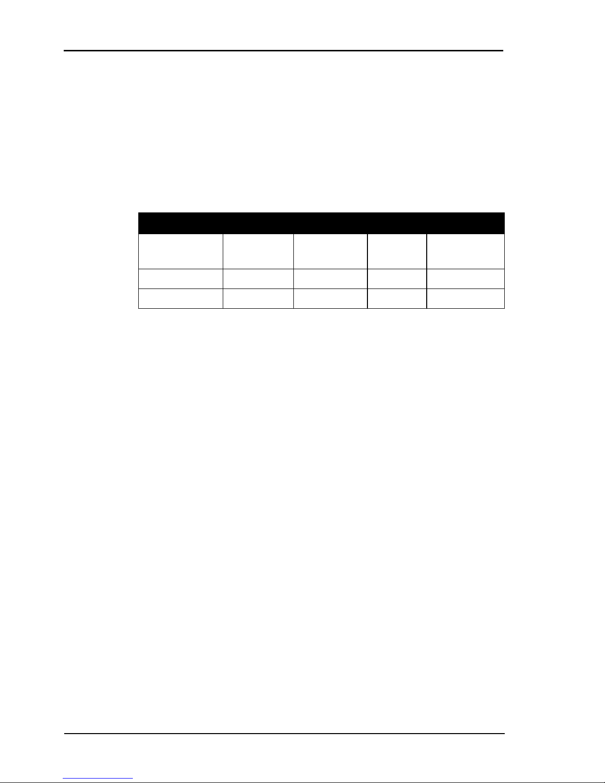
1.3 Features
The plug-on board of type ME-5001 is a 48 bit digital I/O board with
bit-pattern detection for the base boards of the ME-5000 series. You can
configure individual subdevices alternatively for frequency measurement
resp. pulse generator on demand (see chapter 4 from page 21).
Overview:
*Alternative configuration can be activated via ME-iDC.
• Digital I/O ports: The ME-5001 has totally 48 bi-directional I/Os.
The direction can be defined for each of the six 8 bit ports
(subdevice 0..5) by software. After powering up, all the ports are
configured as inputs.
• Frequency counter: The concept of the "configurable subdevices"
allows subdevice 0 to be employed as a frequency counter. Eight inde
pendent channels are available for measuring the frequency and duty
cycle of rectangular signals (max. 5.5 MHz).
• Pulse generator: The concept of the "configurable subdevices"
allows subdevice 1 to be employed as a rectangular wave generator.
Eight independent channels are available for the output of a periodic,
rectangular signal at up to 5.5 MHz with a variable duty cycle.
• Signal level 3.3 /5 V: The signal level of all the digital inputs/outputs
and of the control lines can be switched together between 3.3 V and
5 V, depending on the external circuitry. The changeover is made for
all the ports of the plug-on board at once using software.
• For optimum signal matching, you are able to activate, via software,
an active 110 Ω termination at the digital inputs/outputs of the
subdevices 0..3.
DIO FIO* 3.3V/5V Ter min at ion
ME-5001
(Subdevice 0/1)
2 x 8 bit DIO 8 FI channels
8 FO channels
4 x 8 bit 4 x 8 bit
(Subdevice 2/3) 2 x 8 bit DIO -- 4 x 8 bit 4 x 8 bit
(Subdevice 4/5) 2 x 8 bit DIO -- -- --
Ta b l e 1: Overview of the ME-5001
Page 9

Manual ME-5001 Rev. 1.1E
Meilhaus Electronic Page 9 Introduction
• Bit-pattern detection: The bit-pattern of a digital input or output
port can be monitored if required. Depending on the configuration,
an interrupt can be triggered in response to a change in the bit-pattern.
Thanks to the DMA architecture, the data can be transferred very quickly
between the PC's working memory and the board. In streaming mode,
an input/output rate of up to 30 MS/s, in which all the ports must par
ticipate, is possible. (See also table 2 on page 22). The actual transmission
rate will depend on the operating mode and the configuration of your
computer.
Depending on requirements, you can select from the following operation
modes:
• Single: In this operating mode, a single value can be read or written
under software control (see chapter 4.1.1 on page 23).
• Interrupt: For interrupt handling in the "bit-pattern change" mode
(see chapter 4.2 on page 27).
Customer-specific versions of the firmware are available on request.
1.4 System Requirements
The ME-5001 requires a base board of the ME-5000 series and occupies
a free PCI Express or CompactPCI slot but without using the PCI slot
connector. This saves the resources of your PC. The board is supported
by the Meilhaus Intelligent Driver System (ME-iDS) from Windows
2000 upwards (Linux under development).
1.5 Software Support
The plug-on boards of the ME-5000 series are supported by the
Meilhaus Intelligent Driver System (ME-iDS). The ME-iDS is a unified
driver system usable across devices and operating systems. It supports
Windows 8/7/Vista/XP/2000 (Linux under development) and contains
a universal function library (API) for programming.
You will find a detailed description of the functions in the ME-iDS
manual, a copy of which is on the CD/DVD supplied.
Please also observe the notes in the appropriate README files.
Page 10

Rev. 1.1E Manual ME-5001
Introduction Page 10 Meilhaus Electronic
Page 11

Manual ME-5001 Rev. 1.1E
Meilhaus Electronic Page 11 Initial Operation
2 Initial Operation
Please read your computer manual instructions on how to install new
hardware components before installing the board.
2.1 Software Installation
• Installation under Windows
The following basic procedure should be used:
If you have received the driver software as an archive file please un-pack
the software before installing the board. First choose a directory on your
computer (e. g. C:\Temp\Meilhaus\ME-iDS).
Use the Meilhaus Intelligent Driver System (ME-iDS) for programming
your new data acquisition hardware. For installation and operation of the
driver system please follow the documentation in electronic form included with the software package.
• Installation under Linux
Note the installation instructions included with archive file of the appropriate driver.
Linux under development!
2.2 Test Program
• ME-PowerLab3: Run the program from the Windows Start menu.
This will allow you to test all the important functions of the hardware.
• You will find simple test programs in the SDK of the ME-iDS, in the
"Test Executables32" or "Test Executables64" subfolders.
Page 12

Rev. 1.1E Manual ME-5001
Initial Operation Page 12 Meilhaus Electronic
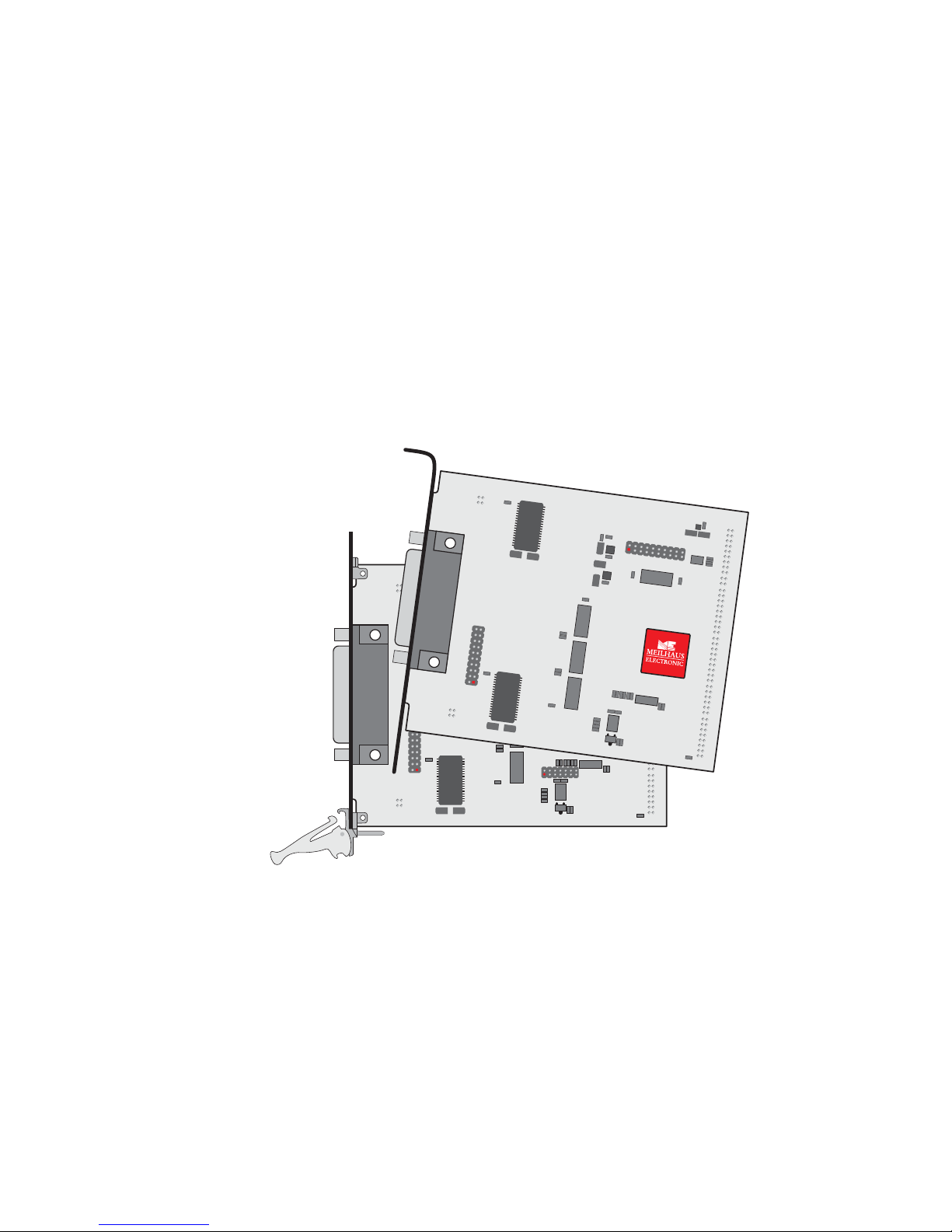
2.3 Fitting the Plug-on Board
The boards should be handled with care in order to make sure that the
device is not damaged by electrostatic discharge (ESD), mechanical stress
or unsuitable current surges. Precautions should also be taken to avoid an
electric shock. Ensure that standard ESD safty precautions are taken. At
least one hand should be grounded in order to dissipate any static charge.
Observe the following procedure:
1. If the base board is installed, you must first remove it in order
to be able to insert the plug-on board. Here you should
observe the procedure as described in the manual for your PC
system.
2. Make sure that electrostatic discharges cannot take place
through the plug-on board or the base board as you plug it in.
Follow the standard ESD safty precautions.
3. Push the plug-on board carefully, and with only a little force,
on to the male connector provided for it (see diagram
1, items
1, 2 and 3). Check that the board is fully plugged in.
4. Choose two adjacent slots for the installation. If necessary,
remove an additional mounting bracket for the slot of the
plug-on board.
5. Carefully plug the combination of the base and plug-on board
into the computer.
6. Screw the two slot brackets down firmly.
7. Close the PC system again.
Page 13

Manual ME-5001 Rev. 1.1E
Meilhaus Electronic Page 13 Initial Operation
Diagram 1: Fitting the plug-on boards
Page 14

Rev. 1.1E Manual ME-5001
Initial Operation Page 14 Meilhaus Electronic
Page 15
Manual ME-5001 Rev. 1.1E
Meilhaus Electronic Page 15 Hardware
3 Hardware
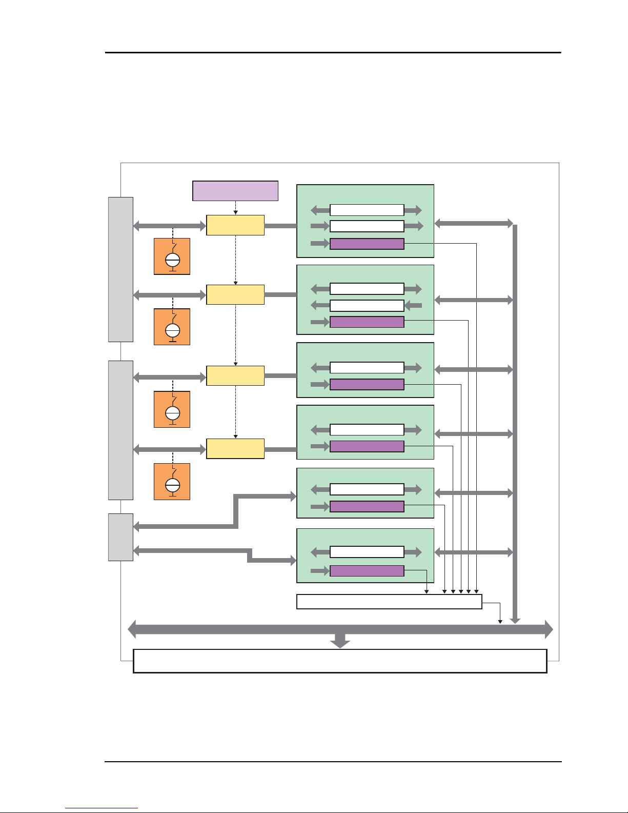
3.1 Block Diagram
Diagram 2: Block diagram of the ME-5001
The pin assignment of the connectors can be found in the appendix (see
"Pinout" on page 32).
25-pin D-sub female (ST1)via ST2via ST3
Local address/data bus to the base board
Base Board
ME-5001
R
T
Logic level selectable
(3.3 V/5 V)
Buffer
Buffer
Buffer
Buffer
R
T
DIO_0..7 / FI_0..7
DIO_8..15 / FO_0..7
DIO_16..23
DIO_24..31
R
T
R
T
DIO_32..39
DIO_40..47
Subdevice 0
Subdevice 1
Subdevice 2
Subdevice 3
Subdevice 4
Subdevice 5
IRQ
Interrupt logic
Bit-pattern change
FO (impulse gen.)
DIO (single)
Bit-pattern change
DIO (single)
Bit-pattern change
DIO (single)
DIO (single)
Bit-pattern change
Bit-pattern change
DIO (single)
Bit-pattern change
FI (freq. measurement)
DIO (single)
Page 16

Rev. 1.1E Manual ME-5001
Hardware Page 16 Meilhaus Electronic
In the following chapters you will learn more about the external wiring
of the individual subdevices. Chapter 4 from page 21 describes the operation modes and the programming.
3.2 ME-5001 cPCI/PCIe
Diagram 3: ME-5001 cPCI/PCIe
ST1
ME-5001
REV.: 1.3
cPCIPCIe
ST2
ST3
Page 17
Manual ME-5001 Rev. 1.1E
Meilhaus Electronic Page 17 Hardware
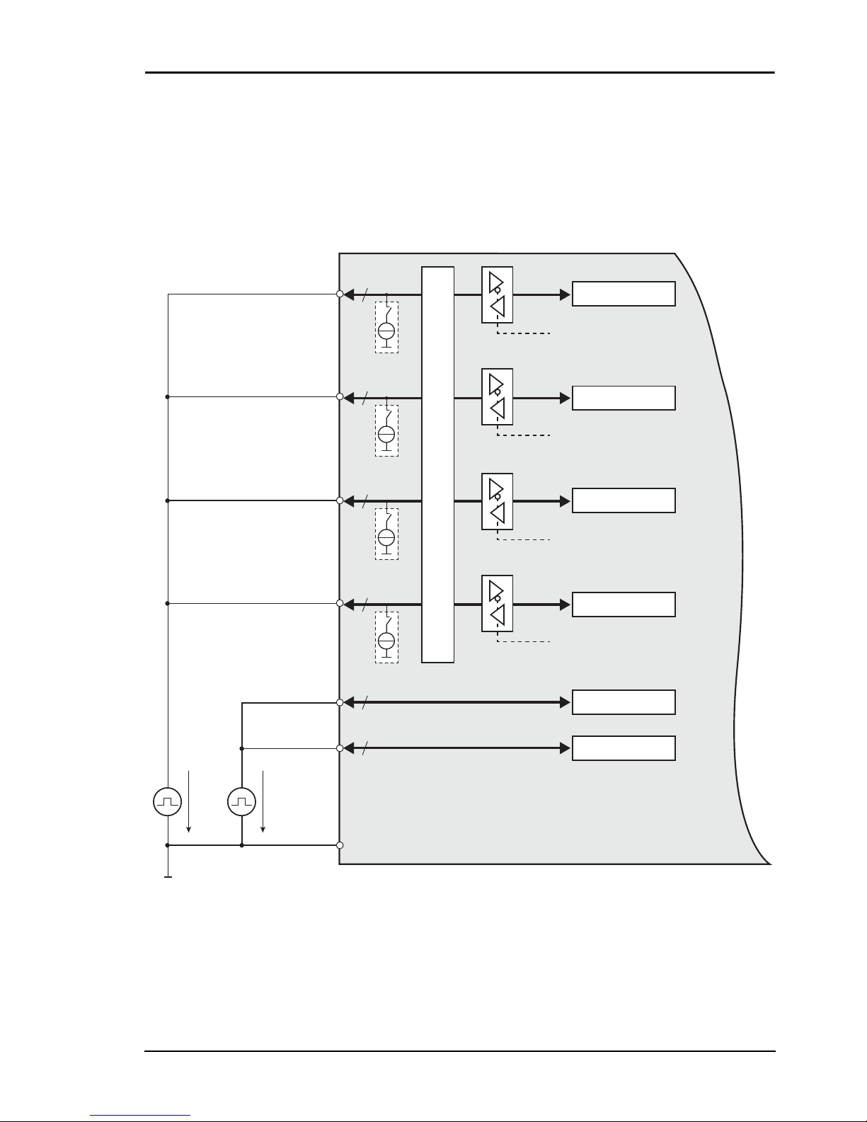
3.3 Digital Input/Output
The ME-5001 has totally six 8 bit digital I/O ports (subdevice 0..5). In
single operation mode, the subdevices can be configured independently
of one another, as input or output. The direction of the ports is defined
by software. After powering up, all the ports are configured as inputs.
Diagram 4: Wiring of digital inputs/outputs
Please read chapter 4.1.1 from page 23 for programming the different
operating modes.
DIO_0..7
DIO_8..15
DIO_16..23
DIO_24..31
GND_PC
R
T
Subdevice 1
8
In/Out
R
T
Subdevice 0
8
In/Out
3.3 V/5 V
R
T
Subdevice 3
DIO_32..39
DIO_40..47
8
Subdevice 4
8
Subdevice 5
8
In/Out
R
T
Subdevice 2
8
In/Out
Level switching
3.3 V
5 V
5V
Page 18

Rev. 1.1E Manual ME-5001
Hardware Page 18 Meilhaus Electronic
3.3.1 Digital Inputs
When wiring the inputs, note that the voltage level must be observed (see
the specifications on page 29) and that a reference to the PC ground
(GND_PC) must be established (see diagram 4).
3.3.2 Digital Outputs
When wiring the outputs, note that the voltage level must be observed
(see the specifications on page 29) and that a reference to the PC ground
(GND_PC) must be established (see diagram 4).
I
Out
= I
OL
= IOH = 24 mA per pin.
3.3.3 External Trigger
On the ME-5001 no external trigger inputs are available. However you
can monitor the bit-pattern of a digital input port. As soon as the
specified event occurs, an interrupt can be issued and passed directly to
the PC. See chapter 4.2 on page 27.
3.4 Frequency Input/Output
The concept of the "configurable subdevices" of the ME-5000 series
gives you the option of using individual subdevices with an alternative
functionality. The associated configuration is carried out with the
ME-iDC configuration tool before your application is called.
The following channels are available:
• Frequency measurement (FI= "Frequency Input"):
8 independent inputs for measuring the frequency and duty cycle of
rectangular signals (max. 5.5 MHz).
• Pulse generator (FO= "Frequency Output"):
8 independent outputs for the output of a periodic rectangular signal
at up to 5.5 MHz with a variable duty cycle.
The associated pins are identified as FI_0..7 and FO_0..7 in the terminal
assignment on page 11. After powering up, the pins FO_0..7 are configured as inputs i. e. in high impedance state. Not until the driver has been
loaded driver become conductive.
Page 19

Manual ME-5001 Rev. 1.1E
Meilhaus Electronic Page 19 Hardware
Diagram 5: Wiring the frequency inputs/outputs
The specifications for the digital I/O ports apply to the wiring of the
FI/FO lines. A reference to the PC ground (PC_GND) must always be
established. The maximum output current is I
Out
= IOL = IOH = 24 mA.
The frequency counters and pulse generators are configured by software.
Please read chapter 4.2 on page 27 for programming the frequency input/output.
3.5 External Interrupt
If required, you can also monitor the bit-pattern of the digital inputs.
The "bit-pattern change" mode is available on the ME-5001. As soon as
the specified event occurs, an interrupt is issued and passed directly to the
PC.
The digital inputs/outputs are programmed in the single operation
mode. The interrupt handling is carried out with the meIOIrq… func
-
tions; see also chapter 4.2 on page 27.
3.6 Additional Functions
You can make the following settings for adapting to your application
regardless of the operating mode.
FI_x
GND_PC
TTL level
"Frequency measurement inputs"
FO_x
GND_PC
TTL level
"Pulse generator output"
R
L
I
Out
= 24mA
Page 20

Rev. 1.1E Manual ME-5001
Hardware Page 20 Meilhaus Electronic
3.6.1 Termination
For optimum signal matching, you can enable via software, an active
110 Ω termination at the digital inputs/outputs of the subdevices 0..3.
The termination circuits are effectively protected against overload by the
combination of current limiting and thermal shutdown (with automatic
return to service).
3.6.2 Logic Level Matching
The signal level of subdevices 0..3 can be switched together between
3.3 V and 5 V, depending on the external circuitry. The changeover for
the pins DIO_0..31 is made in common by software.
Page 21

Manual ME-5001 Rev. 1.1E
Meilhaus Electronic Page 21 Programming
4Programming
The Meilhaus Intelligent Driver System (ME-iDS) is included with the
ME-5001 for programming purposes. The ME-iDS is a unified driver
system usable across devices and operating systems. It supports Windows
2000 and above, as well as Linux systems (in preparation) with Kernel 2.6
and above, and contains a universal function library (API) for all
common programming languages. (You can find the scope of the current
software support in the readme files of the ME-iDS.)
A detailed description of the functions can be found in the ME-iDS
manual (see the CD/DVD included with the board, or online under:
www.meilhaus.com/download). Other details, such as the assignment of
the subdevices and device-specific arguments, may be found in the help
file (in the help file format under Windows, *.chm), which you can open
via the "ME-iDS Control Center" in the information area of the taskbar
(usually at the bottom right of the screen), or through the Windows Start
menu.
The plug-on board of type ME-5001 is a discrete device with six "subdevices", beginning with the index "0". The functionality of the subdevices
can be specified by the user through selecting a pre-defined configuration. The desired configuration is loaded into the board by the ME-iDC
configuration tool before your application starts. Using the standard
configuration, (ID 0), the board is ready to operate immediately. You will
find an overview of the currently available configurations in the following
table:
Page 22

Rev. 1.1E Manual ME-5001
Programming Page 22 Meilhaus Electronic
Subdevice-Konfigurationen ME-5001
*Standard configuration at shipment. The most recently selected
configuration in the ME-iDC is stored in a non-volatile memory on the
board, and is automatically loaded after a restart.
Depending on requirements, you can select from the following
operation modes:
• Single: Individual values can be read or written in this operation
mode.
• Interrupt: For the interrupt handling in the bit-pattern change mode
(see chapter 4.2.1 starting on page 27).
Subdevice type… …subtype I/Os
ID of the
configuration
Subdevice 0 (DIO, FI)
Digital input/output (DIO) Single 8 bit
bi-directional
0*
Frequency input (FI) Single 8 channels 1
Subdevice 1 (DIO, FO)
Digital input/output (DIO) Single 8 bit
bi-directional
0*
Frequency output (FO) Single 8 channels 1
Subdevice 2 (DIO)
Digital input/output (DIO) Single 8 bit
bi-directional
0*
Subdevice 3 (DIO)
Digital input/output (DIO) Single 8 bit
bi-directional
0*
Subdevice 4 (DIO)
Digital input/output (DIO) Single 8 bit
bi-directional
0*
Subdevice 5 (DIO)
Digital input/output (DIO) Single 8 bit
bi-directional
0*
Ta b l e 2: Subdevice configuration ME-5001
Page 23

Manual ME-5001 Rev. 1.1E
Meilhaus Electronic Page 23 Programming
4.1 Single Operation Mode
Individual values can be read or written in this operating mode.
Notes:
• In the single operating mode, all subdevices of the ME-5001 can be
used bidirectionally.
• After powering up, the bidirectional ports are configured as inputs.
• A port that is configured as an output can also be read back!
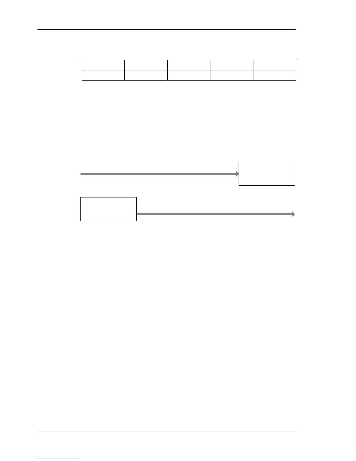
4.1.1 Digital Input/Output
The input/output of individual digital values is carried out in the single
operating mode. All subdevices are of type ME_TYPE_DIO, subtype
ME_SUBTYPE_SINGLE. The configuration is done separately for each
subdevice.
Diagram 6: Digital input/output in single operating mode
Please observe the ME-iDS manual and the ME-iDS help file (*.chm) for
the procedure. You can open both these documents through the
"ME-iDS Control Center) or through the Windows Start menu.
Please read chapter 3.3 on page 17 for the wiring of the digital I/Os.
Operation mode Speed Trigger
Single Single value Input/output via software
Interrupt
(Bit-pattern detection)
f
IRQmax.
= 10 kHz Ext. trigger signal at a digital
input/output port
Ta b l e 3: Operation modes summary
ME-5001
4
DIO_0..47
Subdevice 0..5
“Digital-I/O“
Page 24
Rev. 1.1E Manual ME-5001
Programming Page 24 Meilhaus Electronic
4.1.2 Frequency Input/Output
Before you can use the "Frequency measurement" or "Pulse generator"
modes, it is necessary, prior calling your application, to run the ME-iDC
configuration tool in order to specify the configuration for the corresponding subdevice (see also table 2 on page 22).
The programming of the frequency measurement and the pulse generator
is always done in the single operating mode. The subtype of the subdevices is always ME_SUBTYPE_SINGLE.
Diagram 7: Frequency input/output in single operation mode
Please read the ME-iDS manual and the ME-iDS help file (*.chm)
carefully prior to programming. You can open both of these documents
through the "ME-iDS Control Center or through the Windows Start
menu.
Two variables are introduced to describe the rectangular signal, and apply
equally to input and output. One value indicates the period T, while the
other value provides the duration of the pulse of the first phase of the
period t1P. For frequency measurement, the measurement starts with the
first rising edge, and finishes with the next rising edge. The falling edge
that lies between them defines the end of the first phase. In pulse generator mode, output normally starts with a high level, changing to the low
level when the first phase has elapsed.
ME-5001
4
Subdevice 0
“Frequency In“
FI_0..7
Subdevice 1
“Frequency Out“
FO_0..7
Page 25

Manual ME-5001 Rev. 1.1E
Meilhaus Electronic Page 25 Programming
Diagram 8: Signal definition
The time reference is provided by a 66 MHz counter. It is configured
using the meIOSingleConfig() function. A period of 15.15ns follows from
this, and is defined as the smallest unit of time. It is referred to below as
"1 tick". The resolution for T and t1P is therefore 1 tick (see also the
specifications on page 29).
Note that the value of the maximum period T
max.
depends on the duty
cycle. A distinction is drawn between rectangular signals with an asymmetrical duty cycle T
max. asym.
and a symmetrical duty cycle T
max. sym.
.
The figures for the ME-5001 are:
T
max. asym.
= 32.5 s (0.03 Hz); T
max. sym.
= 65 s (0.015 Hz)
The wiring of the frequency inputs/outputs can be found in chapter 3.4
on page 18.
4.1.2.1 Frequency Measurement
With the frequency measurement operating mode (FI= "Frequency Input") you can determine the period or frequency, and the duty cycle of
rectangular signals up to about 5.5 MHz. The resolution is 1 tick =
15.15 ns. The measurement always starts at a rising edge. On the
ME-5001, all 8 frequency measuring channels (FI_0…7) are addressed
as subdevices of type ME_TYPE_FI, subtype ME_SUBTYPE_
SINGLE. Each channel can be programmed independently.
0
High
T
max. asym
= ½ T
max. sym
Low
50% 100%
Period
(ME_IO_SINGLE_TYPE_FIO_TICKS_TOTAL)
Pulse duration of the first phase of the period
(ME_IO_SINGLE_TYPE_FIO_TICKS_FIRST_PHASE)
„First phase“
T
t
1P
sym. asym.
Page 26

Rev. 1.1E Manual ME-5001
Programming Page 26 Meilhaus Electronic
Note: If the frequency and duty cycle are the magnitudes you want, these
can easily be calculated from the values returned for <pdTime>. The
formula is:
Frequency [Hz] = 1/period [s]
Duty cycle [%] = ("duration of the first phase of the period" [s] /
period [s]) × 100
4.1.2.2 Pulse Generator
In the pulse generator operating mode (FO = "Frequency Output") you
can output rectangular signals with a variable duty cycle at frequencies of
up to 5.5 MHz and with a resolution of 1 tick. On the ME-5001, all 8
pulse generator channels (FO_0…7) are addressed as subdevices of type
ME_TYPE_FO, subtype ME_SUBTYPE_SINGLE. Each channel can
be programmed independently.
The first phase of the rectangular signal is "high" by default. By setting
the ME_IO_SINGLE_TYPE_FO_START_LOW flag it is also possible
to start the output with a "low" level.
All the pulse generator channels can be started synchronously or independent form each other.
Note: An output channel can also be read back!
Page 27

Manual ME-5001 Rev. 1.1E
Meilhaus Electronic Page 27 Programming
4.2 Interrupt Operation
On the ME-5001 you can monitor the bit-pattern of a subdevice
configured as an input for changes in one or more masked bits. As soon
as the first edge that meets the trigger condition arrives, an interrupt is
generated and passed directly to the PC.
The programming the digital input/output is carried out in the single
operation mode. The subdevice must be of type ME_TYPE_DIO. The
interrupt handling is done by the meIOIrq… functions.
Diagram 9: Interrupt options
Please observe the ME-iDS manual and the ME-iDS help file (*.chm) for
the
procedure. You can open both of these documents through the
"ME-iDS Control Center“ or through the Windows Start menu.
4.2.1 Bit-pattern Change
In the bit-pattern change mode, one or more bits that are to be monitored for a change of state can be defined (masked). A 32-bit wide
argument per subdevice contains the mask. For each input pin both one
bit for rising edge and one bit for falling edge are available. If the state of
at least one bit masked with a "1" changes (0 → 1 or 1 → 0), an interrupt
is issued (see diagram 10 on page 28).
ME-5001
4
IRQ to PC
OR
DIO_0..7
Bit-pattern change
8
DIO_8..15
Bit-pattern change
8
DIO_16..23
Bit-pattern change
8
DIO_24..31
Bit-pattern change
8
DIO_32..39
Bit-pattern change
8
DIO_40..47
Bit-pattern change
8
Page 28

Rev. 1.1E Manual ME-5001
Programming Page 28 Meilhaus Electronic
In what is known as the "extended format" of interrupt handling (see the
ME-iDS manual), two bits are available for the interrupt status of each
pin. One is for the rising edge, and one for the falling edge. The bits for
the falling edges are assigned to the bit b7…0, while the bits for the rising
edges are assigned to the bits b23…16.
Diagram 10: Bit-pattern change
Example (see diagram 10):
By writing the value 00800004Hex as a mask value (see parameter
<iIrqArg> of the function meIOIrqStart()), bit 2 is monitored for a fal-
ling edge, and bit 7 for a rising edge. A rising edge now is to arrive at bit 7,
so that an interrupt is issued and in the interrupt status value bit b23
returns "1". Any edges that might arrive at pins labelled with an "X" are
ignored. Only the change in state of a pin whose edge is set to "1" in the
parameter
<iIrqArg> can issue an interrupt.
The interrupt event is evaluated with the function meIOIrqWait(). We
recommend using what is known as the "extended format" to obtain
detailed information about the triggering edge.
Mask value
(32 bit)
IRQ
status value
(32 bit)
Digital port (8 bit)
DIO_7
2
0
xxxxxx
000000 0010000000 0001000000000000
b23
b7..0
b23..16
Page 29

Manual ME-5001 Rev. 1.1E
Meilhaus Electronic Page 29 Specifications
Appendix
ASpecifications
(Ambient temperature 25 °C)
PC Interface via base board
Digital Input/Output
Frequency Input/Output
PCI Express bus 32 bit, 33 MHz, 3.3 V, PCI Express x1, specification version 2.0
CompactPCI bus 32 bit, 33 MHz, 5 V, specification PICMG 2.0 R3.0
Plug&Play is fully supported
Measured quantity/criteri-onCondition/explanation Value
Number I/Os Subdevice 0..5 16 bit bidirectional
Operating modes Single Software-triggered reading/writing
Interrupt Monitoring the digital ports for a
change in the bit-pattern
External trigger inputs DIO_0..47
External trigger edges rising, falling, any
Output level U
OL
at I
OUT
= 24 mA max. 0.5 V
U
OH 3.3 V
at I
OUT
= -24mA min. 2.4 V
U
OH 5V
at I
OUT
= -24 mA min. 2.4 V
Input level U
IL
at Vcc = 3.3 V or 5 V max. 0.8 V
U
IH 3.3 V
at Vcc = 3.3 V min. 2 V
U
IH 5V
at Vcc = 5 V min. 2 V
Input current I
IN
±1 μA
Output current I
OUT
per pin max. 24 mA
Reference ground PC ground (GND_PC)
Availability Alternative subdevice configuration via ME-iDC
Signal form Rectangular
Page 30

Rev. 1.1E Manual ME-5001
Specifications Page 30 Meilhaus Electronic
Frequency measuring channels
Pulse generator channels
Measured quantity/criteri-onCondition/explanation Value
Reference ground PC ground (GND_PC)
Number of channels (FI_0…7) 8 inputs (TTL)
Input level see digital I/O
Input current see digital I/O
Period (T) T
min.
= T
min. asym.
= T
min. sym.
T
max. asym.
Tmax. sym.
181,81 ns (5.5 MHz)
32.5 s (0.03 Hz)
65 s (0.015 Hz)
Duty cycle Variable, depending on T Measurable in steps of 1 tick
Resolution 1 tick 15,15 ns
Accuracy ±15,15 ns
Operating modes Single
Measured quantity/criteri-onCondition/explanation Value
Reference ground PC ground (GND_PC)
Number of channels (FO_0…7) 8 outputs (TTL)
Output level see digital I/O
Period (T) T
min.
= T
min. asym.
= T
min. sym.
T
max. asym.
Tmax. sym.
181,81 ns (5.5 MHz)
32.5 s (0.03 Hz)
65 s (0.015 Hz)
Duty cycle Variable, depending on T Adjustable in steps of 1 tick
Resolution 1 tick 15,15 ns
Accuracy ±15,15 ns
Operating modes Single
Page 31

Manual ME-5001 Rev. 1.1E
Meilhaus Electronic Page 31 Specifications
Interrupt
General Data
CE Certification
Measured quantity/criteri-onCondition/explanation Value
Interrupt sources Passed directly to the PC Bit-pattern change
Measured quantity/criteri-onCondition/explanation Value
Power supply via base board 3,3V/5V
Current consumption additional to base board 0,50…0,9A (full load)
Board dimensions
(without mounting bracket
and connector)
base board requires its own slot 120mm x 100mm
Connections ST1 25-pin D-sub female socket
ST2 20-pin IDC socket
(opt. 25-pin D-Sub, see accessories)
ST3 20-pin IDC socket
(opt. 25-pin D-Sub, see accessories)
Operating temperature 0…70 °C
Storage temperature -40…100 °C
Air humidity 20…55% (non-condensing)
EU directive 89/336/EMC
Emission EN 55022
Immunity EN 50082-2
Page 32

Rev. 1.1E Manual ME-5001
Pinout Page 32 Meilhaus Electronic
BPinout
Legend for pinouts
DIO_0..7 Digital input/output (subdevice 0)
DIO_8..15 Digital input/output (subdevice 1)
DIO_16..23 Digital input/output (subdevice 2)
DIO_24..31 Digital input/output (subdevice 3)
DIO_32..39 Digital input/output (subdevice 4)
DIO_40..47 Digital input/output (subdevice 5)
FI_0..7 Frequency measuring inputs (alternative configuration)
FO_0..7 Pulse generator outputs (alternative configuration)
VCC_OUT VCC output (+5V from PC)
GND_PC Common ground (= PC ground)
n.c. Pins not used
Page 33

Manual ME-5001 Rev. 1.1E
Meilhaus Electronic Page 33 Pinout
B1 25-pin D-Sub (ST1)
Diagram 11: 25-pin D-sub socket ME-5001 (ST1)
The digital I/Os of ST1 are assigned to subdevice 0 and 1.
*Use as a frequency measuring input (FI_x) or pulse generator output (FO_x) is
only possible after appropriate configuration using ME-iDC. The other pins of
the relevant subdevice can then no longer be used for digital input/output.
n.c.
n.c.
(FI_1*) DIO_1
(FI_3*) DIO_3
(FI_5*) DIO_5
(FI_7*) DIO_7
(FO_1*) DIO_9
(FO_3*) DIO_11
(FO_5*) DIO_13
(FO_7*) DIO_15
GND_PC
VCC_OUT
13
12
11
10
9
8
7
6
5
4
3
2
1
25
24
23
22
21
20
19
18
17
16
15
14
n.c.
n.c.
n.c.
DIO_0 (FI_0*)
DIO_2 (FI_2*)
DIO_4 (FI_4*)
DIO_6 (FI_6*)
DIO_8 (FO_0*)
DIO_10 (FO_2*)
DIO_12 (FO_4*)
DIO_14 (FO_6*)
GND_PC
VCC_OUT
Page 34

Rev. 1.1E Manual ME-5001
Pinout Page 34 Meilhaus Electronic
B2 Additional Sockets (ST2/ST3)
For adaption from ST2 (DIO_16..31) resp. ST3 (DIO_32..47) to a 25pin D-sub female connector one resp. two optional mounting brackets
are required. Use type ME-AK-D25F/S for PCI Express slots resp. MEAK-D25F/S(cPCI) for CompactPCI slots.
Please note when plugging on the flat ribbon cable, make sure that pin 1
of the flat ribbon cable (red marked line) is connected on to the IDC
socket ST2 resp. ST3 as shown in diagram 12.
Diagram 12: Connecting the additional sockets ST2/ST3
20-pin IDC socket for ST2 and ST3
Pin Labeling (ST2/3) Pin Labeling (ST2/3)
20 DIO_17 / 33 19 DIO_16 / 32
18 DIO_19 / 35 17 DIO_18 / 34
16 DIO_21 / 37 15 DIO_20 / 36
14 DIO_23 / 39 13 DIO_22 / 38
12 DIO_25 / 41 11 DIO_24 / 40
10 DIO_27 / 43 9 DIO_26 / 42
8 DIO_29 / 45 7 DIO_28 / 44
6 DIO_31 / 47 5 DIO_30 / 46
4 GND_PC 3 GND_PC
2 VCC_OUT 1 VCC_OUT
Ta b l e 4: Pinout of the 20-pin IDC socket (ST2/3)
ST1
ME-5001
REV.: 1.3
cPCIPCIe
ST2
ST3
12
1
2
19
20
18
16
14
12
10
8
6
4
2
17
15
13
11
9
5
3
1
7
1
1
Page 35

Manual ME-5001 Rev. 1.1E
Meilhaus Electronic Page 35 Accessories
C Accessories
We recommend the use of high-quality connecting cables with a largely
calculated cable cross-section.
ME AB-D25M
25-pin D-Sub terminal block (male)
ME AK-D25
25-pin D-Sub connection cable (male-female), 2 m
ME-AK-D25F/S (cPCI)
Additional mounting bracket for cPCI- resp. PCI Express slots for adaption of ST2 (DIO_16..31) resp. ST3 (DIO_32..47) to a 25-pin D-Sub
female connector. E. g. for connecting the ME-63Xtend- or ME-UB
series.
ME AK-D2578/4000
Special connection cable for connection of the ME-63Xtend series via
25-pin D-Sub female connectors of the ME-5001.
ME-63Xtend series
External relay and digital I/O boards (suitable for DIN rail mounting).
To be connected by the special connection cable ME AK-D2578/4000.
ME-UB series
Desktop relays and digital I/O boxes. To be connected by the special connection cable ME AK-D2515/4000.
Further accessories can be found in the current Meilhaus Electronic
catalogue, or on the Internet under www.meilhaus.de
Page 36

Rev. 1.1E Manual ME-5001
Technical Questions Page 36 Meilhaus Electronic
D Technical Questions
D1 Hotline
If you should have any technical questions or problems that can be put
down to your Meilhaus device, please send a fax to our hotline:
Fax hotline: + 49 (0) 89/89 01 66 28
eMail: support@meilhaus.de
Please give a full description of the problems and as much information as
possible, including operating system information.
D2 Service address
If a technical error should occur with your device please contact us at the
following address:
Meilhaus Electronic GmbH
Service Department
Fischerstraße 2
D-82178 Puchheim/Germany
If you want to send back a device to be repaired it is strictly necessary to
request for a RMA number and to follow the notes to deal with the RMA
process. Please attach a detailed error description of the problem, including information about operating system and application software!
D3 Driver Update
The current driver versions for Meilhaus devices and our manuals in PDF
format are available under www.meilhaus.com.
Page 37

Manual ME-5001 Rev. 1.1E
Meilhaus Electronic Page 37 Index
EIndex
A
Accessories 35
Adapter card 34
Adaption cable 35
B
Bit-pattern change 27
Block diagrams 15
C
Connection assignments 32
Connection cable 35
Counter
Operation Modes 27
D
Digital I/O
Programming 23
Wiring 17
Digital inputs 18
Digital outputs 18
Driver Update 36
D-sub socket 33
E
External interrupt 19
External trigger 18
F
Features 8
Frequency input/output
Programming 24
Wiring 18
Frequency measurement 18, 25
H
Hardware description 15
I
Interrupt
Programming 27
Wiring 19
Introduction 5
L
Logic level matching 20
O
Operation Modes
Frequency measurement 25
Interrupt 27
Pulse generator 26
Single mode 23
P
Pinout 32
Programming 21
Bit-pattern change 27
Frequency input/output 24
Interrupt 27
Single mode 23
Pulse generator 18, 26
S
Scope of supply 7
Service and Support 36
Single operation mode 23
Software support 9
Specifications 29
System requirements 9
T
Terminal blocks 35
Termination 20
Test program 11
W
Warnings 5
Page 38

Rev. 1.1E Manual ME-5001
Index Page 38 Meilhaus Electronic
 Loading...