

Meilhaus Electronic ME-1400, ME-1400A, ME-1400E, ME-1400EA, ME-1400B Electronic Manual
...
Meilhaus Electronic Manual
ME-1400 Series
(PCI- and CompactPCI-Versions)
TTL Digital I/0 and Counter Boards

Imprint
Manual ME-1400 Series
Revision 3.0
Revised: 2018-05-28
Meilhaus Electronic GmbH
Am Sonnenlicht 2
D-82239 Alling bei München
Germany
www.meilhaus.de
© Copyright 2018 Meilhaus Electronic GmbH
All rights reserved. No part of this publication may be reproduced
or distributed in any form whether photocopied, printed, put on
microfilm or be stored in any electronic media without the
expressed written consent of Meilhaus Electronic GmbH.
Important note:
The information contained in this manual has been reviewed with
great care and is believed to be complete and accurate. Meilhaus
Electronic assumes no responsibility for its use, any infringements
of patents or other rights of third parties which may result from
use of this manual or the product. Meilhaus Electronic assumes no
responsibility for any problems or damage which may result from
errors or omissions. Specifications and instructions are subject to
change without notice.
Note the Meilhaus Electronic general terms of business:
www.meilhaus.de/en/infos/my-shop/tob/
All trademarks acknowledged. All trademarks are property of their
respective owners.

Content
1 Introduction ........................................................... 5
1.1 Important Notes ............................................................... 5
1.1.1 Use in Accordance with the Requirements ....................... 5
1.1.2 Improper Application ...................................................... 6
1.1.3 Unforseeable Misapplications .......................................... 6
1.1.4 Warning ........................................................................ 6
1.2 Package Contents ............................................................. 7
1.3 Features .......................................................................... 7
1.4 System Requirements ....................................................... 8
1.5 Software Support ............................................................. 8
2 Starting up ............................................................ 9
2.1 Software Installation ......................................................... 9
2.2 Test Program .................................................................... 9
3 Hardware ............................................................ 10
3.1 Block Diagram ME-1400/A/B/E/EA/EB ................................ 10
3.2 Digital-I/O Section ........................................................... 11
3.3 Counter (8254) ............................................................... 11
3.3.1 Cascading the Counter ................................................. 12
3.3.2 Clock Output and Interrupt Control ............................... 13
3.3.3 Pulse Width Modulation ................................................ 13
3.3.4 Pull-Up/Pull-Down Resistors .......................................... 14
4 Programming ....................................................... 17
4.1 Digital I/O ....................................................................... 17
4.1.1 Simple Input/Output ..................................................... 18
4.2 Counter .......................................................................... 18
4.2.1 Standard Operation Modes ........................................... 18
4.2.2. Clock Source .............................................................. 19
4.2.3 Cascading ................................................................... 19
4.2.4 Pulse Width Modulation ................................................ 20
4.3 External Interrupt ........................................................... 20
5 Appendix ............................................................. 21
A Specification .......................................................................... 21
B Pinout ................................................................................... 23
B1 ME-1400/A/B ................................................................. 23
B2 ME-1400E/EA/EB ........................................................... 24
B3 IDC-Connector for B-Versions (ST2) ................................. 25
B4 Additional Mounting Bracket ............................................ 26
C Accessories ........................................................................... 27
D Technical Questions ................................................................ 28
D1 Hotline ........................................................................... 28
E Index ..................................................................................... 29

1 Introduction
Valued customer,
Thank you for purchasing this device from Meilhaus Electronic. You
have chosen an innovative high technology product that left our
premises in a fully functional and new condition.
Please take the time to carefully examine the contents of the
package for any loss or damage that may have occurred during
shipping. If there are any items missing or if an item is damaged,
please contact us immediately.
Before installing the board in your computer, we recommend you
read this manual carefully, especially the chapter describing board
installation.
The descriptions in this manual concern PCI- and CompactPCI
versions of the ME-1400 series if not otherwise noted.
1.1 Important Notes
1.1.1 Use in Accordance with the Requirements
The PC boards of the ME series are designed for acquisition and
output of analog and digital signals with a PC. Depending on type
install the models of the ME series into:
a free PCI-slot (PCI versions) or
a free CompactPCI slot (3 HE cPCI versions)
Please note the following instructions and specifications as
presented in this manual (Appendix A, Specifications):
Please ensure sufficient heat dissipation for the board within
the PC housing.
All unused inputs should be connected to the ground reference
of the appropriate functional section. This avoids cross talk
between the input lines.
Note that the computer must be powered up prior to
connecting signals by the external wiring of the board.
As a basic principle, all connections to the board should only be
made or removed in a powered-down state of all components.

Ensure that no static discharge occurs while handling the
board or while connecting/disconnecting the external cable.
Ensure that the connection cable is properly connected. It must be
seated firmly on the D-Sub connector and must be tightened with
both screws, otherwise proper operation of the board cannot be
guaranteed.
1.1.2 Improper Application
PC plug-in boards for the PCI- or CompactPCI-bus may not be taken
into operation outside of the PC. Never connect the devices with
voltage-carrying parts, especially not with mains voltage.
Make sure that no contact with voltage-carrying parts can happen
by the external wiring of the device. As a basic principle, all
connections should only be made or removed in a powered-down
state.
1.1.3 Unforseeable Misapplications
The device is not suitable to be used as a children’s toy, in the
household or under unfavourable environmental conditions (e.g. in
the open). Appropriate precautions to avoid any unforeseeable
misapplication must be taken by the user.
1.1.4 Warning
The device was developed and produced in accordance to the EMC
low-voltage-directive 73/23/EWG. When putting the device into
operation, especially with voltages greater than 42 V, please follow
the appropriate standards, installation instructions and national
safety standards. Meilhaus Electronic GmbH assumes no
responsibility for damage in case of faulty installation, operation or
handling.
1.2 Package Contents
We take great care to ensure your delivery is complete.
Nonetheless, please check the list enclosed to verify the contents
of your delivery. You should find included:
Digital I/O and counter board of the ME-1400 series for PCI-
or CompactPCI-bus.
Manual in PDF format on CD/DVD.
Driver software on CD/DVD.
ME-1400E/EA/EB: D-sub 37-pin male-connector.
ME-1400/A/B: D-sub 78-pin male-connector.
ME-1400EB: ribbon cable from IDC-connector to 37-pin D-Sub-
female-connector mounted on additional mounting bracket.
1.3 Features
The ME-1400 series is provided as a digital I/O and counter board
for PCI- resp. CompactPCI-bus compatible).
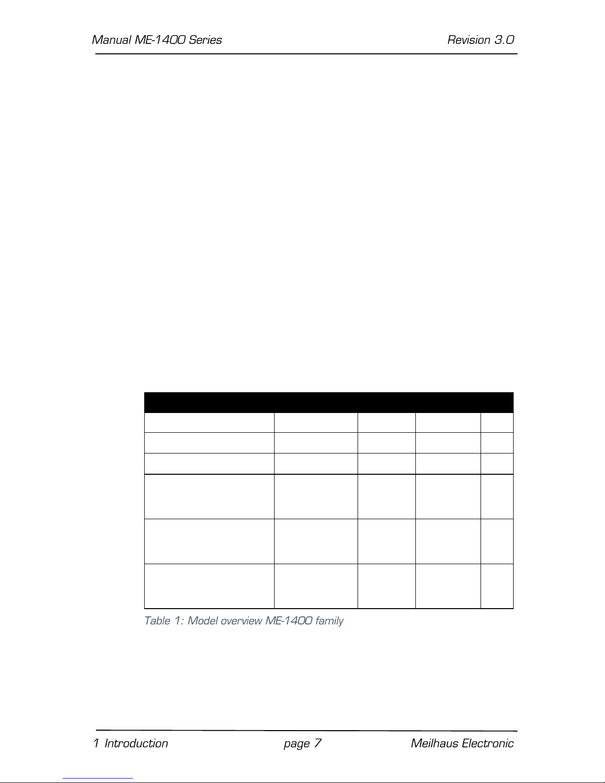
Model Overview
Model
Connector
TTL IOs
Counter
IRQ
ME-1400 PCI/cPCI
78-pin D-Sub
24 – –
ME-1400A PCI/cPCI
78-pin D-Sub
24
3 x 16 bit
✔
ME-1400B PCI/cPCI
78-pin D-Sub
48
6 x 16 bit
✔
ME-1400E PCI
(connector compatible
with ME-14)
37-pin D-Sub
24 – –
ME-1400EA PCI
(connector compatible
with ME-14A)
37-pin D-Sub
24
3 x 16 bit
✔
ME-1400EB PCI
(connector compatible
with ME-14B)
2 x 37-pin DSub
48
6 x 16 bit
✔
The boards resp. boxes of the ME-1400 series provide 24 or 48
TTL compatible digital-I/O lines (8-bit ports) and up to 30
independent programmable 16-bit counters (8254 compatible),
depending on model.
All models with counters provide a 10 MHz oscillator which is independent from the system clock of the PC. The frequency can be
set to 1 MHz by software. The boards have an external interrupt
line available with exception of the models ME-1400/E.
The external connections to the board are realized with a 37-pin
D-Sub (ME-1400E versions) resp. a 78-pin D-Sub connector
(ME-1400/A/B). The ME-1400EB has an extra IDC connector on
the board to enable access to the expanded signals for the second
digital-I/O and counter units of the board. A flat ribbon cable and an
extra mounting bracket with a 37-pin D-Sub female connector are
included with the package.
1.4 System Requirements
The ME-series may be installed into any PC (Intel® Pentium®
processor) with a free standard PCI- resp. CompactPCI-slot
(32 bit, 33 MHz, 5 V). The board is supported by the Meilhaus
Electronic Intelligent Driver System (ME-iDS).
1.5 Software Support
The ME-series is supported by the Meilhaus Electronic Intelligent
Driver System (ME-iDS). The ME-iDS is a unique driver system
covering different devices and operating systems. It supports
Windows 2000/XP/Vista and Windows 7, 8.1, 10 and contains a
universal function library (API) for all common programming
languages.
A detailed description of the functions can be found in the ME-iDS
manual on the CD/DVD enclosed.
Please also note the corresponding README-files.
2 Starting up
Please read your computer’s instruction manual on how to install
new hardware components before installing the board.
2.1 Software Installation
Installation under Windows
The following basic procedure should be used:
If you have received the driver software as an archive file please unpack the software before installing the board. First choose a
directory on your computer (e.g. C:\Temp\Meilhaus\ME-iDS).
Use the Meilhaus Electronic Intelligent Driver System (ME-iDS) for
programming your new data acquisition hardware. For installation
and operation of the driver system, please follow the
documentation in electronic form included with the software
package.
Installation under Linux
Note the installation instructions included with archive file of the
appropriate driver.
2.2 Test Program
For simple testing of the board use the corresponding test
program provided with the ME-iDS.
 Loading...