

Meiko K-200 User Manual
K-200 SERIES
Meiko's K-Tronic series rack conveyor warewashers
combine state-of-the-art advanced features with
economical and reliable operation. The K-Tronic series
features the lowest water consumption of any NSF-rated
rack conveyor warewasher, and makes use of an exclusive
pumped, heated auxiliary rinse zone to make use of the
rinse water a second time for pristine, consistent results.
Meiko’s exclusive Waste Air Heat Recovery System
reclaims the waste air generated by the machine as free
energy to pre-heat the incoming rinse water, saving energy.
Other standard features include computer-positioned wash
arms (and prewash arms, on models so equipped) that
are pre-assembled into easily-removed manifolds. Wash
nozzes are slotted and concave to minimize clogging, and
feature captivated end caps which can’t be lost during
cleaning. K-Tronic series machines also feature Meiko’s
Mike 3 electronic controller, and double-wall insulated
construction. As with all products synonymous with the
name “Meiko,” engineering excellence, manufacturing
quality and performance come to the forefront in the
K-Tronic series rack conveyors.
HOT WATER SANITIZING
SINGLE-TANK
RACK CONVEYOR
WAREWASHERS
K-200 K-200 PW K-200 LPW
• Model K-200 includes a 6’ 4-3/4” chamber with one pumped wash section (with 3 hp pump), pumped auxiliary rinse section
(with 3 hp pump) and pumped final rinse section (with 3/4 hp pump).
• Model K-200 PW adds a 19-5/8” prewash section (with 3/4 hp pump) to the base K-200 model (overall length 8’ 1/2”).
• Model K-200 LPW adds a 31-1/2” prewash section (with 3 hp pump) to the base K-200 model (overall length 9’ 1/4”).
Exclusive Features:
• The K-Tronic series features the lowest water
consumption in the industry. Model K-200 consumes 0.35
gallons per rack.
• Pumped auxiliary rinse zone supplements the final rinse
zone, providing pristine, consistent results.
• Waste air heat recovery system reclaims heat generated
by the machine and uses it as free energy to preheat the
incoming rinse water, reducing energy consumption and
allowing hot-water sanitizing from a cold water supply (50°F).
• Double-wall insulated construction retains heat inside
the machine, conserving energy and improving the working
environment.
• Improved drive system permits fast, smooth conveyor
travel. Rack rail-mounted pawl system does not obstruct
the wash pattern.
• Mike 3 electronic controller for fully automatic operation
and advanced service diagnostics. Wash and final rinse are
activated only when a rack is in place to conserve water
and detergent.
K-200 Series • Updated 12-07 Meiko • 917 Airpark Center Drive • Nashville, TN 37217 • (800) 55-MEIKO • FAX (615) 399-6620 • www.meiko.us
Standard Features:
• Computer-positioned wash arms in easily-removed
manifolds feature concave, slotted nozzles to minimize
clogging, and captivated end caps.
• Front-sloping wash tanks
• All 304-series stainless steel construction
• Large, easily-removed pan strainers. Models equipped with
a prewash include a separate prewash scrap basket.
• Powerful 3hp wash pump is vertically-mounted to be selfdraining and easily removed for servicing.
• Single-point drain connection
• Single-point ventilation connection
• Low-level heater protection
Options:
• Revolutionary blower drying system - uses only 3 kW for
heating. Available in two lengths: 23-5/8” (600mm) or 35-1/2”
(900mm)
• CSS Top Chemical Savings System
• Hinged front access doors
• Steam coil or electric tank heating
• Table limit switch
• External vent fan control
• Single-point electrical connection
• 90° loaders and power unloaders

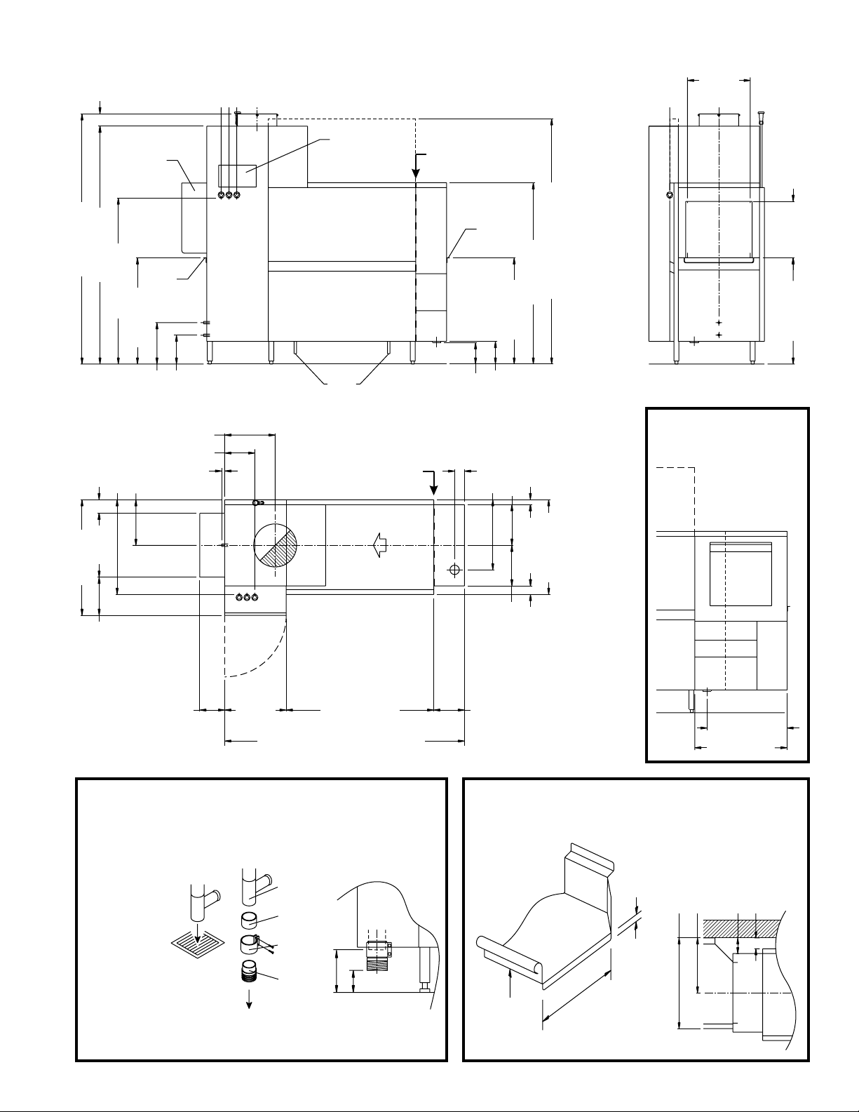
K-200, K-200 PW, K-200 LPW, electric heating
Machines without blower dryer, Left-to-Right
control
Prewash inserted here for
K-200 PW and K-200 LPW
P
panel
splash guard
[above table]
3 7/8"
[100mm]
Horizontal
clearance
1'-8 1/8"
[510mm]
Door open 6'-6 1/2" [1994mm]
4'-10" [1474mm]
1 5/8" [40mm]
2'-2" [660mm]
2'-6 3/8" [770mm]
table
support
2'-10" [864mm]
7 1/4"
[184mm]
1'-10 1/2" [570mm]
1'-1" [330mm]
lip
6 7/8"
[174mm]
3 1/8"
[80mm]
1-3
C
W
D
CSS TOP OPTION
(front view)
9-7/8" [250mm] load
section is replaced with
CSS Top section. Adds
Vertical
clearance
2'-10" [864mm]
1'-6" [458mm]
D
Prewash inserted here for
P
K-200 PW and K-200 LPW
drain
handle
123
C
W
1'-4 1/8" [410mm]
9 5/8" [244mm]
1" [25mm]
table
support
lip
9 1/4"
[235mm]
1'-1 1/4"
[335mm]
4'-5 1/8" [1350mm]
2'-10" [864mm]
2'-6 1/4" [770mm]
1'-2 5/8" [370mm]
6'-8 1/8" [2034mm]
6'-4 1/8" [1934mm]
4 3/8" [110mm]
1'-7 5/8" [500mm] to
overall machine length.
W
C
D
123
1'-8 1/2"
[521mm]
3'-1" [940mm]
1'-1" [330mm]
2 3/4" [70mm]
1'-0 1/4" [310mm]
9 7/8" [250mm]
3'-11 1/4" [1200mm]
K-200: Table-to-table 6'-4 3/4" [1950mm]
K-200 PW: Table-to-table 8' 1/2" [2450mm] ‡
K-200 LPW: Table-to-table 9' 1/4" [2750mm] ‡‡
1'-7 5/8"
[500mm]
UTILITY CONNECTIONS
Drain
D
2-15/16” (75mm) OD vertical, gravity-fed
drain outlet (HDPE piping). Optional 3" NPT
male adapter supplied. Recommend
placement directly above 4” floor drain.
Additional piping to drain (if so required) to
be supplied by customer.
Electrical connection
3 (three) individual terminal blocks at locations
shown. Each connection is 4-wire with
ground (no neutral).
with lockout/tagout strongly recommended
for each supply (provided by customer).
Incoming leads must be appropriately sized
for electrical supply. Opening(s) in the
machine for the supply lines are NOT
provided and should be executed on-site
using appropriate strain relief device(s).
Refer to Page 10 for supply details.
Vent connection
354 CFM (+120 CFM room air recommended)
K-200 Series • Updated 12-07 Page 2
Individual disconnect
Warm water connection (fill)
W
3/4" NPT female pipe connection
• Temperature 110-140°F (43-60°C)
• Pressure 15-25 PSI
• Initial fill - Refer to Page 10
• Hardness 4-6 grains/U.S. gal.
Cold water connection (rinse)
C
3/4" NPT female pipe connection
• Temperature 50°F (10°C)
• Pressure 15-25 PSI
• Consumption 84.7 U.S. gals./hour
• Hardness 4-6 grains/U.S. gal.
8" [203mm] splash
guard [above table]
K-200 PW: 1'-7 5/8" [500mm] prewash
‡
K-200 LPW: 2'-7 1/2" [800mm] prewash
‡‡
DETAIL VIEW: VENT
The vent shroud MUST NOT be connected directly to the machine, as this
prevents room air from being drawn into the shroud. All dimensions shown
are recommendations only. Actual exhaust connection must be adequate
for the exhaust air and comply with all applicable national and local codes.
The waste air connection must be corrosion-resistant and frost-free. In
particular, provision must be made to prevent air temperatures of 32°F/0°C
or colder from reaching the machine at any time. A provision for draining
moisture from the waste air pipe is STRONGLY RECOMMENDED.
Vent shroud
(supplied
by customer)
Machine
exhaust vent
Condensation
channel
Condensation
can be drained
into machine
(drain is
supplied by
customer)
2'-1 5/8" [650mm]
2'-5 1/2" [750mm]
Ø1'-6" [457mm]
Ø1'-4"
[406mm]
Ø1'-1 3/8"
[340mm]
D
3 1/8" [80mm]
3/4" [20mm]
Gap permits room
air to enter vent shroud
3 7/8" [100mm]
K-200, K-200 PW, K-200 LPW, electric heating
Machines without blower dryer, Right-to-Left
3 7/8"
[100mm]
control
splash guard
[above table]
panel
Prewash inserted here for
P
K-200 PW and K-200 LPW
Horizontal
clearance
1'-8 1/8"
[510mm]
6'-8 1/8" [2034mm]
6'-4 1/8" [1934mm]
4 3/8" [110mm]
1'-8 1/2"
3'-1" [940mm]
4'-5 1/8" [1350mm]
2'-6 1/4" [770mm]
[521mm]
table
support
lip
2'-10" [864mm]
9 1/4"
1'-1 1/4"
[335mm]
1'-4 1/8" [410mm]
9 5/8" [244mm]
1" [25mm]
1'-2 5/8" [372mm]
[235mm]
321
C
W
table
support
lip
4'-10" [1474mm]
2'-10" [864mm]
Door open 6'-6 1/2" [1994mm]
D
drain
handle
6 7/8"
[174mm]
7 1/4"
[184mm]
1-3
Vertical
clearance
1'-6" [458mm]
C
W
2'-10" [864mm]
D
CSS TOP OPTION
3 1/8"
Prewash inserted here for
K-200 PW and K-200 LPW
[80mm]
P
1'-10 1/2" [570mm]
1'-1" [330mm]
1 5/8" [40mm]
W
C
2'-2" [660mm]
D
321
2'-6 3/8" [770mm]
(front view)
9-7/8" [250mm] load
section is replaced with
CSS Top section. Adds
1'-7 5/8" [500mm] to
overall machine length.
1'-1" [330mm]
2 3/4" [70mm]
1'-0 1/4" [310mm]
2'-6" [762mm]
1'-6 1/8" [462mm]
D
2'-1 5/8" [650mm]
2'-5 1/2" [750mm]
5 1/8" [132mm]
3 5/8" [92mm]
8" [203mm] splash
guard [above table]
DETAIL VIEW: DRAIN
The machine is equipped with a 2-15/16" (75mm) OD vertical, gravity-fed drain. If possible, the
machine drain can simply be positioned directly above a 4" floor drain.
If a floor drain is not in the correct location, or if local codes require a trap, a 3" indirect drain
line may be attached using the supplied boot, clamp, and 3" NPT male adapter.
Choose a piping
material that:
• Complies with
any applicable
local and
national codes
• Is rated for use
with water
temperatures up
to 180°F/82°C
• Is rated for
3-12 pH to
accommodate
detergents and
rinse aid in the
drain water
K-200 Series • Updated 12-07 Page 3
Direct drain
(recommended
if possible)
1'-7 5/8"
[500mm]
K-200: Table-to-table 6'-4 3/4" [1950mm]
K-200 PW: Table-to-table 8' 1/2" [2450mm] ‡
K-200 LPW: Table-to-table 9' 1/4" [2750mm] ‡‡
Machine
drain
Boot
(supplied)
Clamp
(supplied)
3" NPT male
adapter,
HDPE
(supplied)
To 3" indirect
drain line
(supplied by
customer)
3'-11 1/4" [1200mm]
3 1/2" [90mm]
6 7/8" [174mm]
9 7/8" [250mm]
K-200 PW: 1'-7 5/8" [500mm] prewash
‡
K-200 LPW: 2'-7 1/2" [800mm] prewash
‡‡
DETAIL VIEW: TABLING
Wall clearances shown are for typical 30" D dishtable. Actual clearances will depend
upon table manufacturer and table dimensions.
Feeding and
discharge tables
to be supplied
by others
1"
[25mm]
max.
D
Table lip-in
height
2'-10"
[864mm]
A.F.F.
22" [559mm]
max.
20-1/2" [521mm]
recommended
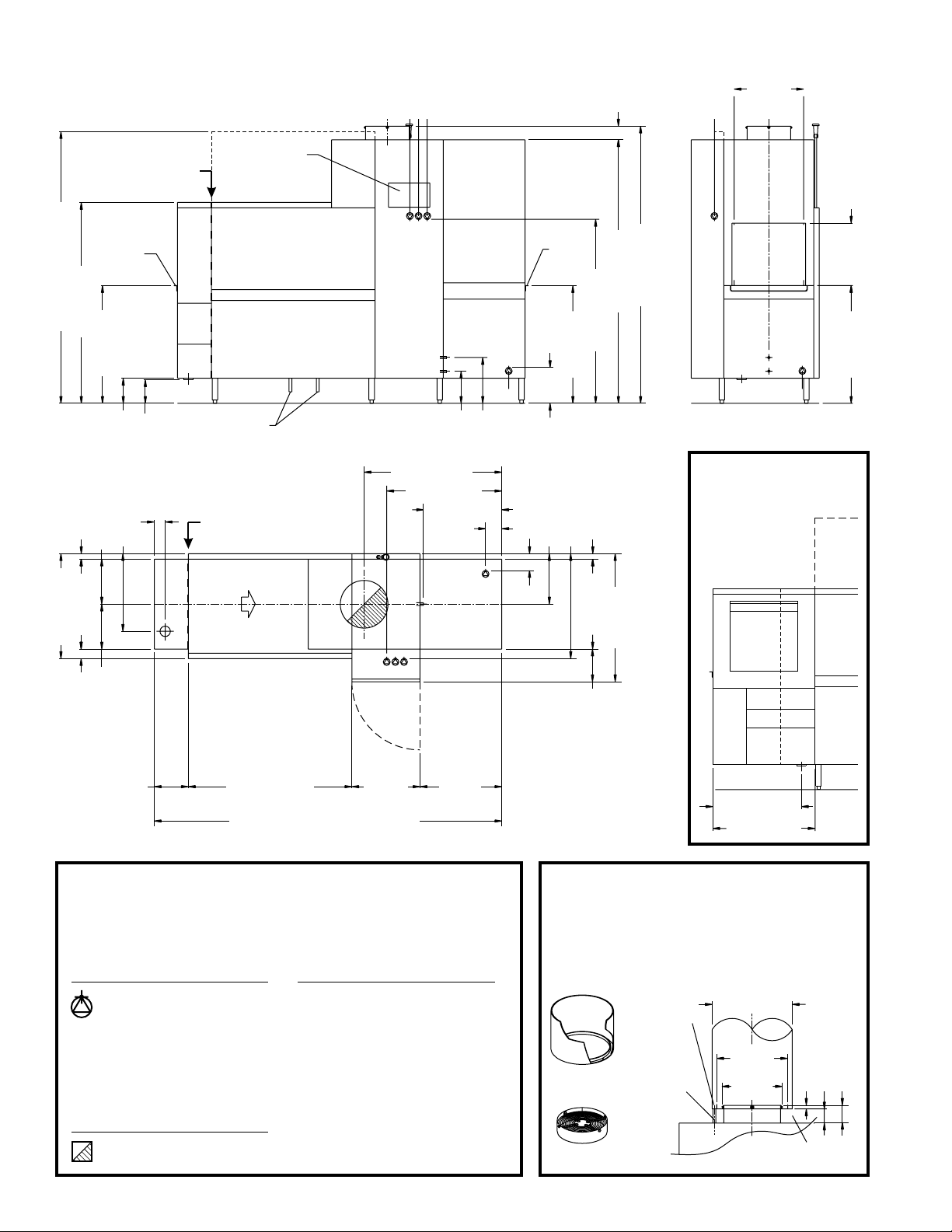
K-200, K-200 PW, K-200 LPW, electric heating
Machines with blower dryer, Left-to-Right
control
Prewash inserted here for
K-200 PW and K-200 LPW
P
panel
3 7/8"
[100mm]
Horizontal
clearance
1'-8 1/8"
[510mm]
Door open 6'-6 1/2" [1994mm]
4'-10" [1474mm]
1 5/8" [40mm]
2'-2" [660mm]
2'-6 3/8" [770mm]
table
support
2'-10" [864mm]
7 1/4"
[184mm]
1'-10 1/2" [570mm]
1'-1" [330mm]
lip
6 7/8"
[174mm]
3 1/8"
[80mm]
1-3
C
4
W
D
CSS TOP OPTION
(front view)
9-7/8" [250mm] load
section is replaced with
CSS Top section. Adds
Vertical
clearance
2'-10" [864mm]
1'-6" [458mm]
D
Prewash inserted here for
P
K-200 PW and K-200 LPW
drain
handle
123
C
W
9 1/4"
3'-3-3/4" [1010mm]
2'-9-1/4" [844mm]
1'-10-5/8" [575mm]
4 3/4"
[120mm]
1'-1 1/4"
[235mm]
4
[335mm]
table
support
lip
10 3/8"
4 7/8" [125mm]
1'-2 5/8" [370mm]
2'-10" [864mm]
[264mm]
2'-6 1/4" [770mm]
4'-5 1/8" [1350mm]
1 5/8" [40mm]
6'-8 1/8" [2034mm]
6'-4 1/8" [1934mm]
1'-7 5/8" [500mm] to
4
overall machine length.
W
C
2'-2" [660mm]
D
123
3'-1" [940mm]
1'-1" [330mm]
2 3/4" [70mm]
* 35-1/2" [900mm] blower dryer
section is also available.
Adds 11-3/4" [300mm] to
overall machine length.
K-200 PW: 1'-7 5/8"
‡
[500mm] prewash
K-200 LPW: 2'-7 1/2"
‡‡
[800mm] prewash
9 7/8" [250mm]
3'-11 1/4" [1200mm]
K-200: Table-to-table 8'-4 3/8" [2550mm]
K-200 PW: Table-to-table 10' 1/8" [3050mm] ‡
K-200 LPW: Table-to-table 10' 11-7/8" [3350mm] ‡‡
1'-7 5/8"
[500mm]
1'-11 5/8"
[600mm] *
UTILITY CONNECTIONS
Drain
D
2-15/16” (75mm) OD vertical, gravity-fed
drain outlet (HDPE piping). Optional 3" NPT
male adapter supplied. Recommend
placement directly above 4” floor drain.
Additional piping to drain (if so required) to
be supplied by customer.
Electrical connection
4 (four) individual terminal blocks at locations
shown. Each connection is 4-wire with
ground (no neutral).
with lockout/tagout strongly recommended
for each supply (provided by customer).
Incoming leads must be appropriately sized
for electrical supply. Opening(s) in the
machine for the supply lines are NOT
provided and should be executed on-site
using appropriate strain relief device(s).
Refer to Page 10 for supply details.
Vent connection
383 CFM (+120 CFM room air recommended)
K-200 Series • Updated 12-07 Page 4
Individual disconnect
Warm water connection (fill)
W
3/4" NPT female pipe connection
• Temperature 110-140°F (43-60°C)
• Pressure 15-25 PSI
• Initial fill - Refer to Page 10
• Hardness 4-6 grains/U.S. gal.
Cold water connection (rinse)
C
3/4" NPT female pipe connection
• Temperature 50°F (10°C)
• Pressure 15-25 PSI
• Consumption 84.7 U.S. gals./hour
• Hardness 4-6 grains/U.S. gal.
9 1/2"
[240mm]
D
2'-1 5/8" [650mm]
2'-5 1/2" [750mm]
DETAIL VIEW: VENT
The vent shroud MUST NOT be connected directly to the machine, as this
prevents room air from being drawn into the shroud. All dimensions shown
are recommendations only. Actual exhaust connection must be adequate
for the exhaust air and comply with all applicable national and local codes.
The waste air connection must be corrosion-resistant and frost-free. In
particular, provision must be made to prevent air temperatures of 32°F/0°C
or colder from reaching the machine at any time. A provision for draining
moisture from the waste air pipe is STRONGLY RECOMMENDED.
Ø1'-6" [457mm]
Ø1'-4"
[406mm]
Ø1'-1 3/8"
[340mm]
air to enter vent shroud
3 1/8" [80mm]
3/4" [20mm]
Gap permits room
Vent shroud
(supplied
by customer)
Machine
exhaust vent
Condensation
channel
Condensation
can be drained
into machine
(drain is
supplied by
customer)
3 7/8" [100mm]
 Loading...