

Meiko K-200 Owner's Manual
K-TRONIC SERIES
High Temperature Sanitizing Rack Conveyor Dishwashers
(USA Version)
OWNER’S INSTALLATION, OPERATION AND
MAINTENANCE MANUAL
Models:
• K-200 • K-200 LPW • K-400 PW
• K-200 PW • K-400 • K-400 LPW
Meiko • 917 Airpark Center Drive • Nashville, TN 37217 • Phone: (615) 399-6600 • (800) 55-MEIKO • Fax: (615) 399-6620
Rev. 12/06
TABLE OF CONTENTS
1. INTRODUCTION ................................. 3
1.1 Overview of Equipment ............................. 3
1.2 General Safety Information........................ 3
or Dispensers .......................................... 13
3.13 Fresh Water Supply Connections ............ 13
3.14 Steam System Connections .................... 14
3.15 Drain Connection ..................................... 15
3.16 Final Assembly ........................................ 15
2. TRANSPORT AND SHIPPING ............ 4
3. INSTALLATION .................................... 4
3.1 Overview of Installation ............................. 4
3.2 Requirements Before Installation .............. 5
3.3 Uncrating, Positioning and Leveling ............. 6
3.4 Tabling Attachment .................................... 8
3.5 Accessing the Utility Connections ............. 8
3.6 Vent Connection ........................................ 9
3.7 Main Electrical Supply Connection .......... 10
3.8 Dispensing System Overview .................. 11
3.9 Installing an External Solid or Liquid
Detergent System .................................... 12
3.10 Installing an External Liquid Rinse
Aid System .............................................. 12
3.11 Wiring External Chemical Dispensing
Systems ................................................... 13
3.12 Connecting Chemical Containers
4. OPERATION ....................................... 18
4.1 Location and Description of Controls....... 18
4.2 Startup ..................................................... 20
4.3 Loading.................................................... 21
4.4 Operation................................................. 22
4.5 Idle Periods ............................................. 22
4.6 Clearing Jams.......................................... 23
4.7 Shutdown ................................................ 23
5. CLEANING ......................................... 24
5.1 Daily Cleaning (or as required) ................ 24
5.2 Weekly Cleaning (or as required) ............ 26
5.3 Exterior Cleaning (as required) ................ 26
5.4 Deliming (as required) ............................. 28
6. TROUBLESHOOTING ........................ 29
AN ELECTRICAL WIRING DIAGRAM IS LOCATED INSIDE THE CONTROL BOX OF THIS MACHINE.
MEIKO K-SERIES RACK CONVEYOR DISHWASHERS HAVE BEEN DESIGNED EXCLUSIVELY
FOR THE WASHING OF DISHES, GLASSWARE, CUTLERY, KITCHEN UTENSILS AND TRAYS
IN A COMMERCIAL OR INSTITUTIONAL SETTING AND MUST NOT BE USED FOR ANY
OTHER PURPOSE WITHOUT THE WRITTEN PERMISSION OF MEIKO.
MEIKO ACCEPTS NO RESPONSIBILITY FOR DAMAGE TO THE APPLIANCE, SURROUNDING
EQUIPMENT OR ENVIRONMENT THAT IS CAUSED BY INAPPROPRIATE INSTALLATION OR
OPERATION, OR FROM ANY SERVICE THAT IS UNDERTAKEN BY NON-AUTHORIZED
PERSONNEL, OR FROM THE USE OF ANY PARTS EXCEPT THOSE THAT ARE APPROVED
BY THE MANUFACTURER. ANY SUCH INSTALLATION, USE OR SERVICE WILL IMMEDIATELY
VOID THE MANUFACTURER’S WARRANTY.
ANY MODIFICATIONS TO THE APPLIANCE THAT ARE PERFORMED WITHOUT THE WRITTEN
PERMISSION OF MEIKO WILL IMMEDIATELY VOID THE MANUFACTURER’S WARRANTY.
Meiko reserves the right to change any specifications without notice at any time.
Meiko • 917 Airpark Center Drive • Nashville, TN 37217
Phone: (615) 399-6600 • (800) 55-MEIKO • Fax: (615) 399-6620
www.meiko.us
Page 2
SECTION 1 - INTRODUCTION
1INTRODUCTION
1.1 Overview of Equipment
Meiko K-Tronic series rack conveyors are
commercial dishwashers designed for
cleaning dishes, glassware, trays, cutlery and
kitchen utensils with a minimum of employee
intervention or supervision.
A control keypad allows easy selection of
three different conveyor speeds to accommodate different levels of soiling. A digital display
permits easy monitoring of operation.
Operation is fully automatic. When a rack is
pushed into the opening of the machine, the
pawl bar drive is activated. The internal Mike
3 electronic controller automatically activates
the prewash (if so equipped), wash and rinse
zones, while maintaining proper tank temperatures.
During idle periods, the wash and rinse pumps
are deactivated to conserve water, energy and
chemicals, while steam coil or electric tank
heaters maintain the water temperature for
quick recovery.
Other features of the unit that affect operation
include:
Mike 3 electronic control system -
Automatically monitors and regulates tank
temperatures. A digital display allows
monitoring of tank temperatures, conveyor
speed, and other information.
Internal booster heater - to ensure constant
final rinse temperatures.
Pumped final rinse - A final rinse pump
ensures constant pressure for the final rinse,
for consistent, outstanding results.
Pumped auxiliary rinse - Final rinse water
is captured and recirculated over the ware as
a pumped pre-rinse, conserving water and
chemicals.
Side-drive system - Racks are advanced
through the machine using pawl bars at the
sides of the rack rails. This provides an
unobstructed wash pattern.
Wash arm manifolds - Wash arms are preassembled into easily-removed manifolds for
faster cleaning. The nozzles are slotted and
concave to minimize clogging. Wash arm end
caps are captivated to prevent their loss
during cleaning.
External drain levers - Foot-operated drain
levers empty the machine quickly and safely.
Front-sloping, V-shaped wash tanks - For
faster draining and easier cleaning.
Double-wall, insulated construction -
Improves operator safety, conserves energy,
and reduces heat loss into the environment.
Waste Air Heat Recovery System - Utilizes
the waste heat generated by the machine to
pre-heat the incoming rinse water, reducing
energy consumption and allowing hot-water
sanitization from a cold water supply.
For efficient and SAFE operation, be sure to
follow the installation and operating
instructions provided in this manual. In
particular, all safety symbols and notices on
the equipment and in the supplied
documentation must be followed.
IMPORTANT
Meiko K-Tronic series rack conveyors have
been designed exclusively for the washing of
dishes, glassware, trays, cutlery and kitchen
utensils in a commercial or institutional setting
and must not be used for any other purpose.
1.2 General Safety Information
The following symbols and headings are used
throughout this manual to indicate possible
hazards to persons or to the equipment. The
symbols and headings are shown in order of
importance. The descriptive text following
these headings is italicized for easy recognition.
WARNING! Possible hazard to
persons, such as from
electrical shock, crushing,
or hot surfaces.
CAUTION Possible hazard to the
dishwasher or to other
equipment.
IMPORTANT Vital information or tips
for the installer or operator.
NOTE Information or tips for the
installer or operator.
Page 3

SECTION 2 - TRANSPORT AND SHIPPING
2TRANSPORT AND SHIPPING
IMPORTANT
• Observe any notices on the crating
material that pertain to shipping.
• Use care when transporting the equipment.
• As you unpack the equipment, check that
all components shown on the shipping
invoice are present and intact. Be sure to
check for shipping damage. If shipping
damage is present, call Meiko Customer
Service at 1-800-868-3840, providing full
details on the customer, serial number and
extent of damage present. Meiko will file
a freight claim based on this information.
WARNING!
In NO EVENT should a damaged
appliance be installed or operated!
3INSTALLATION
3.1 Overview of Installation
Prior to installation, the factory will supply
engineering drawings detailing the machine.
Details include dimensions and complete
utility requirements.
All installations of new Meiko K-Tronic series
rack conveyors will include a factory
representative as a supervisor and advisor.
The factory representative will be able to
advise the installer of special installation
requirements that are outside the scope of
this Manual.
The owner should contract with qualified
personnel to move the appliance to the
installation location, unpack it, and prepare it
for final utility connections.
In most cases, local codes prevent the final
utility connections from being made by any
party other than a licensed electrician,
plumber and/or steam fitter.
IMPORTANT
It is the responsibility of the owner to ensure
that all aspects of the installation comply with
all applicable local and national codes.
IMPORTANT
The appliance’s warranty is not valid until a
Meiko Authorized Service Agent performs a
Performance and Installation Inspection.
Installation of the dishwasher involves the
following steps:
• Verifying that the utility connections are
present, are appropriate for the appliance,
and comply with all applicable local and
national codes.
• Unwrapping the appliance (leaving the
shipping skid in place for easier
movement) and checking for shipping
damage.
• Moving the appliance to the installation
location, removing the skid, and leveling
the feet.
Page 4
• Connecting the machine to tabling.

SECTION 3 - INSTALLATION
• Routing the ventilation system in
accordance with the factory-supplied
engineering drawings and all applicable
local and national codes.
• Connecting the water supply.
• Connecting the electrical supply.
• Connecting the steam supply line (for
machines with steam heating).
• Connecting the steam condensate return
line, and routing it to either a floor drain or
a building condensate return line (for
machines with steam heating).
• Connecting the drain line, and routing it
to a floor drain or building drain.
• Installing the chemical dispensing system
(if so equipped), following the manufacturer’s instructions AND the instructions
in Section 3 of this Manual.
• Contacting your Meiko Authorized Service
Agent to perform a Performance and
Installation Inspection for the machine.
This step also validates the machine’s
warranty.
Meiko may be able to arrange for an
Authorized Service Agent to be present
at the conclusion of the installation
process. Consult your Authorized Sales
Representative for details.
3.2 Requirements Before Installation
Before the installer can uncrate and move the
appliance to the installation location, the
following conditions MUST be met:
• INSTALLATION AREA REQUIREMENTS
- The area MUST be frost-free. Freezing
temperatures (32°F/0°C or lower)
inhibit proper operation and can
damage internal components.
- The area MUST have a firm floor
surface. It is possible to compensate
for uneven flooring by adjusting the
feet.
- The area should be away from
appliances, furniture or surfaces that
can be damaged by steam. If this is
not possible, these items should be
protected from the steam that is
released during normal operation of
the dishwasher.
• UTILTITY CONNECTION REQUIREMENTS
- Connections must be present and
ready for hookup to the appliance. All
utility supplies must comply with the
electrical information labels, with the
information on the data plate, and with
all applicable local and national codes.
- Electrical leads, water supply line(s),
drain line, and the steam supply and
condensate return lines (if so
equipped) must be present.
- The electrical supply must match the
voltage and amperage requirements
specified on the data plate. Circuit
breakers/disconnects (lockout/tagout
is strongly recommended) must be
installed in accordance with all local
and national codes. If the machine
includes multiple electrical connections, each supply must include a
dedicated circuit breaker/disconnect.
- The water supplies must match the
temperatures, pressures and flow
rates specified on the data plate. For
best operation, it should also match the
water hardness specified on the
engineering drawings.
- The steam supply (if so equipped)
must match the pressure and volume
specified on the data plate.
- The ventilation system must be
present and in accordance with the
factory-supplied engineering drawings
and all applicable local and national
codes.
- For units using a chemical dispensing
system, appropriate dispensers or
containers should be installed and
ready for connection to the appliance.
• GENERAL REQUIREMENTS
Authorized personnel should be available
to perform the actual utility connections.
Page 5
SECTION 3 - INSTALLATION
3.3 Uncrating, Positioning and Leveling
IMPORTANT
Most K-Tronic series machines are shipped
in a single section, with wiring and plumbing
connections already in place from the factory.
The Installation section of this manual
describes the installation of these preassembled machines.
Due to space limitations at some installation
sites, it may be necessary for the machine to
be shipped in sections. If this is the case,
assembling the sections is outside the scope
of this Manual. Follow the on-site directions
of the Meiko factory representative to
assemble the sections.
1. Remove all shipping and packaging material from the appliance, including supports and wrappings. Leave the shipping
skid in place at this time to allow for easier
movement to the installation location.
2. Check for shipping damage as described
in Section 2, “Transport and Shipping.” If
damage is present, call Meiko Customer
Service at 1-800-868-3840, providing full
details on the customer, serial number and
extent of damage present. Meiko will file
a freight claim based on this information.
3. Move the appliance to the installation area
using proper moving equipment.
CAUTION
When moving the machine, ALWAYS support it from both ends - not the center.
Figure 3-1: Shipping skids
CAUTION
Be sure that the moving equipment is
positioned underneath the SKID and not
the MACHINE. Some components of the
machine extend down from the frame and
can be damaged if the machine is
improperly lifted. See Figure 3-1.
CAUTION
If the pallet is removed, the frame of the
dishwasher can be damaged by improper
lifting. The machine’s weight must always
be distributed properly using cross-members to protect the frame.
4. After the machine is moved to the correct
location, lower the jacks to the floor, but
leave them in place.
5. Remove the hardware attaching the raised
cross-members of the pallet to the large
runners that rest on the floor. To remove
the hardware, you will need the following
tools:
• Torx TX 20 screwdriver
• Torx TX 25 screwdriver
• Wrench with 10mm hex socket
• #3 Phillips-head screwdriver
6. With the hardware removed, slowly raise
the jacks. The cross-members will lift free,
while the large runners remain on the floor.
7. Remove the runners and lower the jacks.
Then, remove the cross-members.
8. The machine can be moved for a SHORT
distance by carefully sliding it on the floor.
CAUTION
Be careful not to damage the legs on tile
gaps, gratings, or other irregularities in the
floor.
Pallet
cross-member
Page 6
Pallet jacks MUST
support the cross-
members of the
pallet, NOT the
bottom of the
machine!
Pallet
longitudinal
runner
9. Machines that are not equipped with a
blower dryer include a cowling at the exit
end of the machine. If dish tables are already in place, it may be necessary to temporarily remove the cowling to install the
machine. See Figure 3-2.
The cowling is held in place by 8mm hex
head acorn nuts on the inside of the machine. For easy access to the acorn nuts,
simply lift the front access door(s).
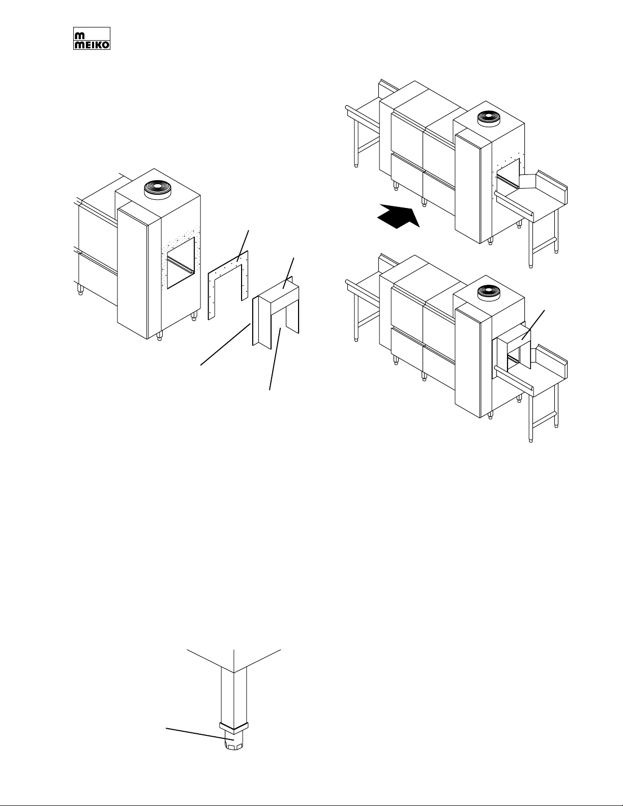
Figure 3-2: Removing the end cowling (if required)
With cowling
removed, set
machine into
place between
Gasket
Cowling
tables
SECTION 3 - INSTALLATION
Replace
cowling
Threaded studs
on back of
cowling
Qty. 16
Reach through
rack opening to
access acorn
nuts and washers
10. Using a spirit level on the conveyor track,
check that the appliance is level in both
directions (front-to-back AND side-toside). If necessary, level the appliance by
rotating the bottom section of each foot
as necessary using a 27mm open-ended
wrench. See Figure 3-3.
CAUTION
The dishwasher MUST be level for proper
operation.
Figure 3-3: Leveling
11. Check the tension on each foot section to
ensure that the legs are sharing the load
evenly. An unbalanced section may cause
water leaks, incorrect operation (by
allowing the machine to shift position),
and/or damage the legs.
12.If you removed a cowling from the
machine in Step 9, replace it on the
machine at this time. Be sure to check that
the rubber gasket that fits between the
cowling and the body of the machine is
properly seated.
13.Run a fine bead of clear silicone sealant
along the top edge of the seam between
the cowling and the machine.
Rotate bottom
section of foot
to adjust height
Page 7
SECTION 3 - INSTALLATION
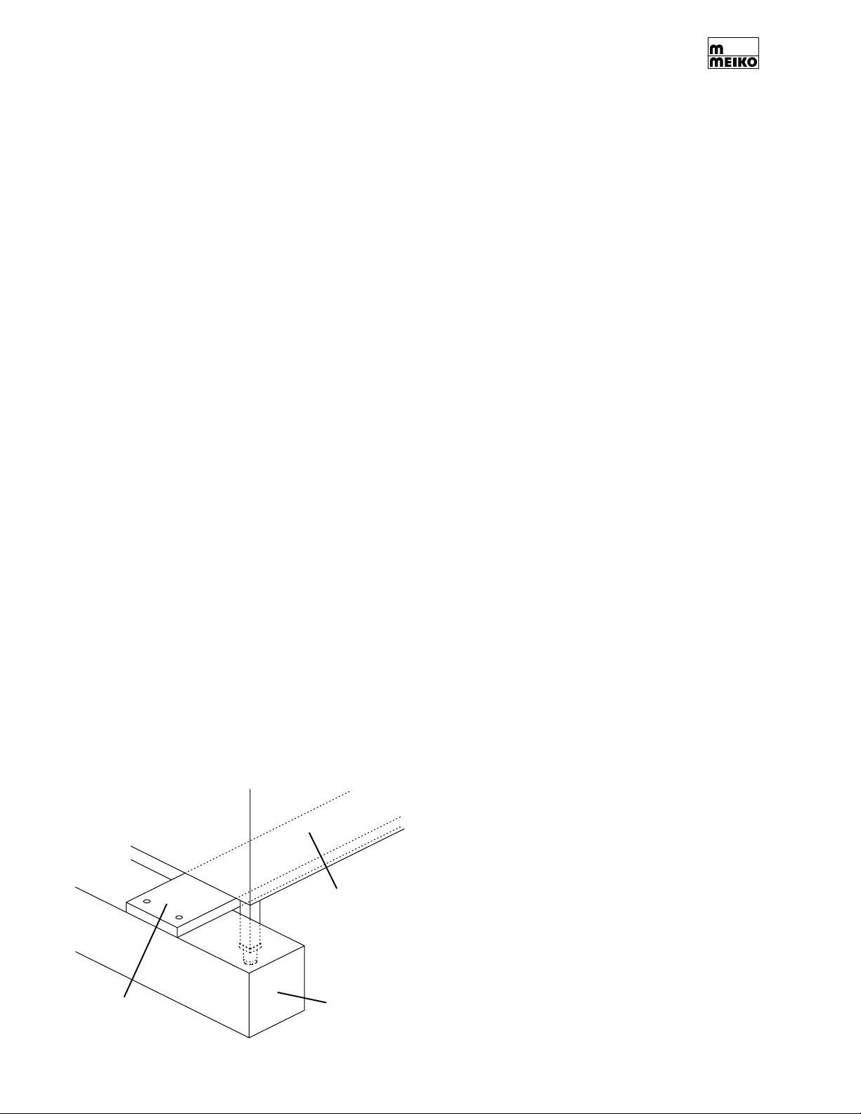
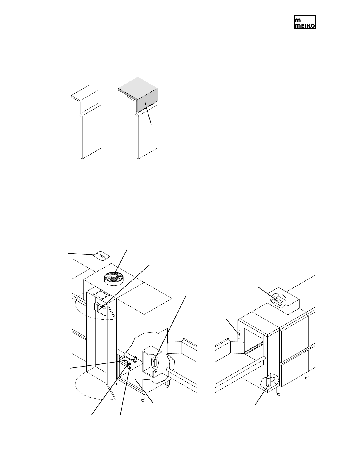
3.4 Tabling Attachment
1. Position the table lip-in at both ends of the
machine, as shown in Figure 3-4. Be sure
to seat the lip-in against the inner face of
the sidewall of the dishwasher.
Figure 3-4:
Tabling
attachment
Sidewall of
dishwasher
Table
lip-in
2. Position the dishwasher and tables as follows:
• Check that the centerline at the
opening of each table is aligned with
the centerline of the rack track of the
dishwasher.
• Check that the surface height of each
table matches the height of the rack
track of the dishwasher, to ensure a
smooth transition. The standard table
surface height is 34” (864mm).
• Check that the dishmachine is level.
The height of the dishmachine, and of
most tables, can be adjusted by rotating
the feet at the end of the legs.
CAUTION
After adjusting the height of the
dishmachine, always check that it is level
to ensure proper operation.
3. After the tables have been positioned
correctly, secure them to the dishwasher
using silicone sealant.
3.5 Accessing the Utility Connections
The utility connections for the machine are
shown in Figure 3-5.
Remove top
access panel to
route electrical
supply
Rinse
aid
Figure 3-5: Accessing utility connections
Unload End
Vent
Electric heat:
Terminal blocks 1-3
Steam heat:
Terminal block
K-200 Series
electric heat with
blower dryer:
Terminal block 4
K-400 Series
electric heat:
Terminal block 4
Detergent
Load End
Steam
connections are
at unload end.
Locations vary
by machine
configuration.
Page 8
Cold water
50°F
Warm water
110-140°F
If machine has a
blower dryer, remove
lower front panel to
access utilities
Drain
CONTROL
CONTROL
SECTION 3 - INSTALLATION
3.6 Vent Connection
IMPORTANT
In some cases, local codes dictate that
ventilation connections be made only by a
certified HVAC professional.
CAUTION
All aspects of the ventilation system must be
corrosion-resistant, frost-free and protected
against freezing temperatures (32°F/0°C or
lower). Freezing temperatures inhibit proper
operation and can damage internal
components.
Meiko K-Tronic series warewashers are
designed for use with a single-point, indirect
ventilation connection. The machine includes
a powered vent that is adequate for short,
vertical runs (10’/3m or less). For longer runs,
it is necessary to provide a powered fan for
the system (for instance, mounted on the roof)
to provide adequate airflow.
CFM ratings for the vent system, as well as
construction details, are provided on the
engineering drawings supplied with the
machine. At the time of installation, the vent
should be in place.
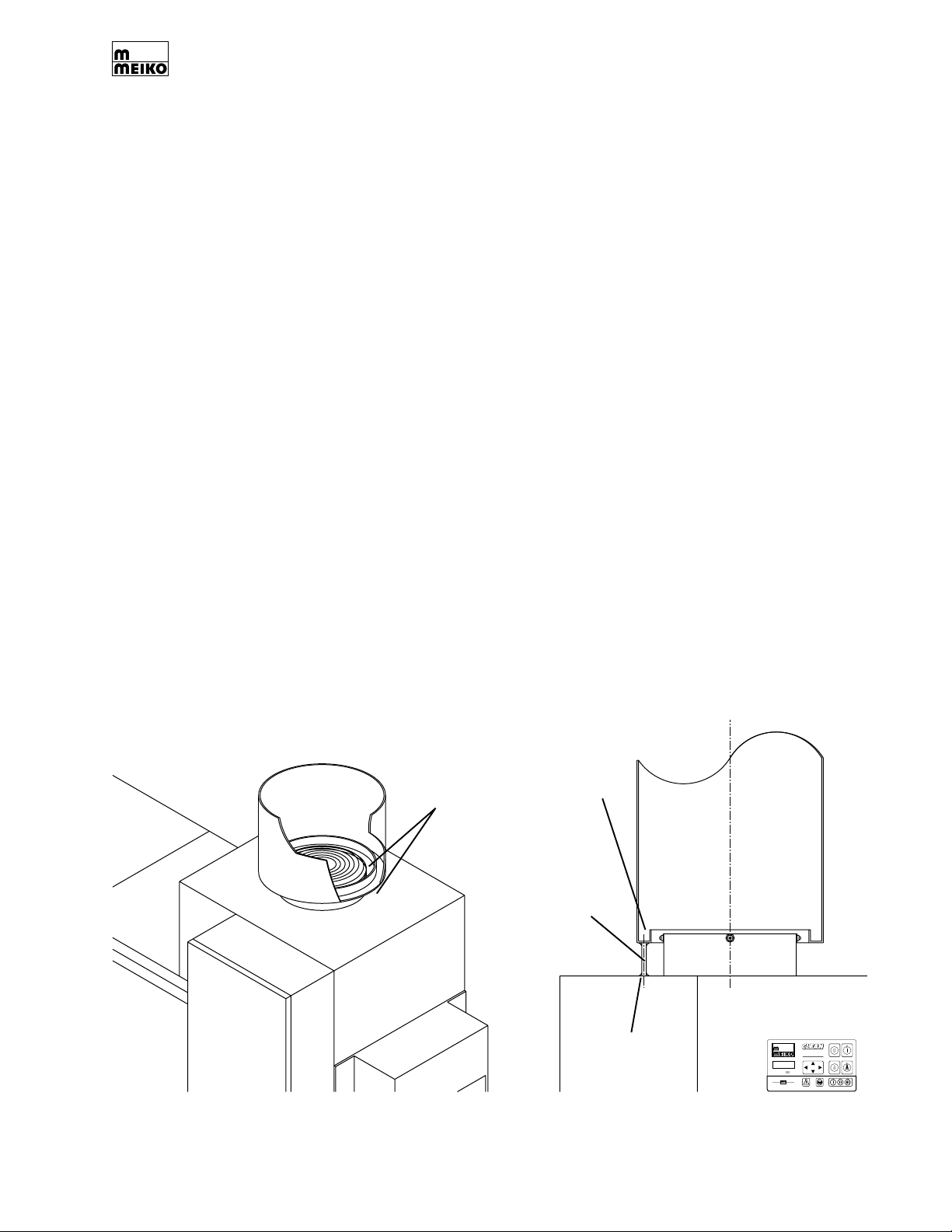
1. Check that the exhaust vent is correctly
positioned above the machine’s fan. See
Figure 3-6. Note that the vent should NOT
be connected directly to the machine so
that room air can be drawn into the vent.
2. If the exhaust vent is powered, check the
airflow using an airflow meter/
anemometer. The CFM rating of the vent
should match the CFM rating specified on
the factory-supplied engineering drawings.
3. If the vent is constructed according to the
engineering drawings, it will include a
1”(25mm)-wide “gutter” along the bottom
edge to collect condensation. If desired,
this condensation can be drained directly
through the top panel of the machine at
the location shown in Figure 3-6.
A 1/4” dia. stainless steel tube is recommended for this purpose. Note that the
drainage tube should be installed on the
side of the vent AWAY from the control
panel as shown in Figure 3-6.
After installation, the seams between the
tube, vent and machine should be sealed
with silicone sealant.
Figure 3-6: Vent connection
Gap permits
room air to
enter vent
Condensation
channel
Condensation
drain tube (if
used - supplied
by customer)
installed on side
of vent AWAY
from control
panel
Silicone
sealant
Control
panel
CONTROL
controlled
Page 9
SECTION 3 - INSTALLATION
3.7 Main Electrical Supply Connection
WARNING!
Check that the circuit breaker/fused
disconnect is in the OFF position and
that the unit is switched off before
making the electrical utility connections.
IMPORTANT
In some cases, local codes dictate that
electrical supply connections be made only
by a certified professional.
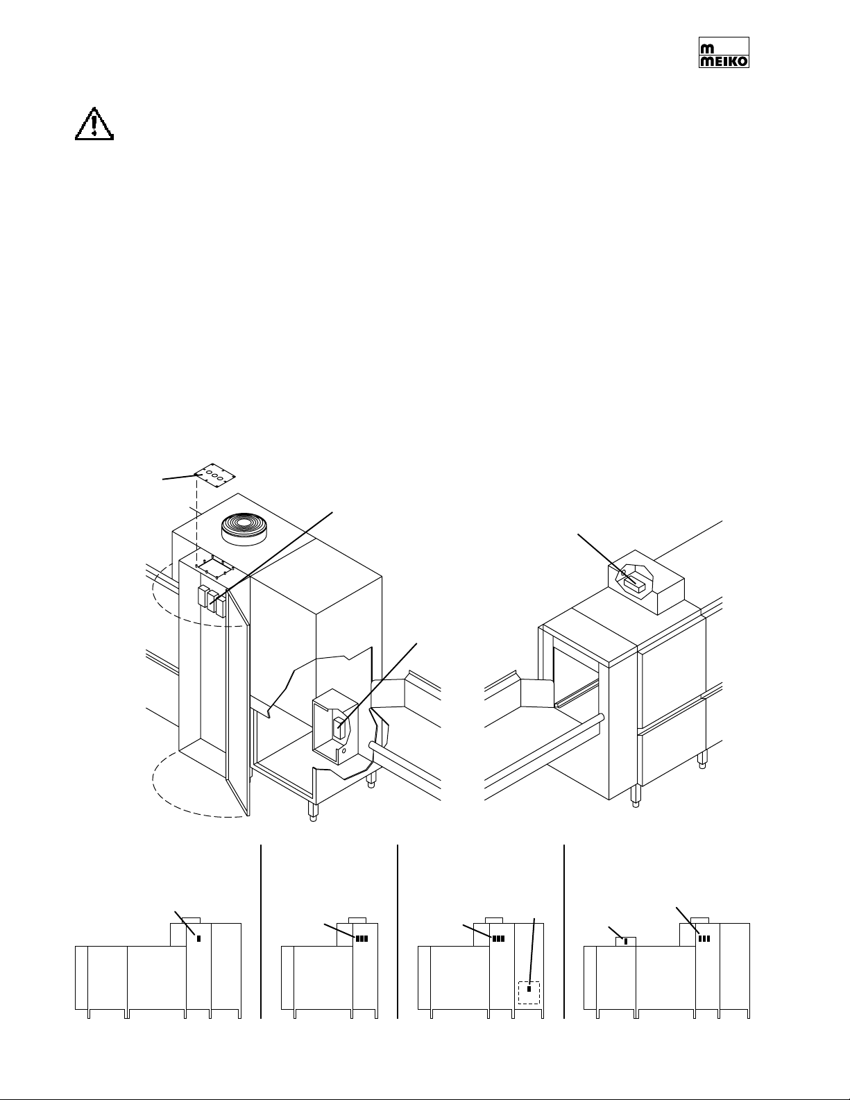
1. Refer to Figure 3-7. Determine the
locations of the electrical terminal blocks
as follows:
• All steam-heated machines use a
single terminal block inside the control
compartment.
Figure 3-7: Electrical connections
Remove top
access panel to
route electrical
supply
Electric heat:
Terminal blocks 1-3
Steam heat:
Terminal block
Route from
ABOVE machine.
Unload
End
• Electrically-heated machines have
either 3 or 4 terminal blocks. Terminal
Blocks 1-3 are located inside the
control compartment.
• K-200 electrically-heated machines
that are NOT equipped with a blower
dryer use only these three terminal blocks.
• K-200 electrically-heated machines
that are equipped with a blower dryer
have a fourth terminal block (Terminal
Block 4) located inside a secondary
electrical box underneath the blower dryer.
• All K-400 electrically-heated machines
have a fourth terminal block (Terminal
Block 4) located inside a secondary
electrical box on top of the wash tank.
K-400 Series
electric heat:
Terminal block 4
Route from
ABOVE machine.
K-200 Series
electric heat with
blower dryer:
Terminal block 4.
Remove lower front
panel for access.
Route from
BELOW machine.
Load
End
K-200 or K-400 series
with steam heat
Terminal
block
Page 10
K-200 series with
electric heat,
no blower dryer
Terminal
blocks 1-3
K-200 series with
electric heat,
with blower dryer
Terminal
blocks 1-3
Terminal
block 4
K-400 series with
electric heat
Terminal
Terminal
block 4
blocks 1-3
 Loading...