

Meiko K-100E Installation Manual
K SERIES
High Temperature Sanitizing Rack Conveyor Dishwashers
(USA Version)
OWNER’S INSTALLATION, OPERATION AND
MAINTENANCE MANUAL
Models:
• K-44E, K-44ET, K-44S, K-44ST • K-54E, K-54ET, K-54S, K-54ST • K-64E, K-64ET, K-64S, K-64ST
• K-66E, K-66ET, K-66S, K-66ST • K-76E, K-76ET, K-76S, K-76ST • K-86E, K-86ET, K-86S, K-86ST
• K-80E, K-80ET, K-80S, K-80ST • K-90E, K-90ET, K-90S, K-90ST • K-100E, K-100ET, K-100S, K-100ST
Meiko • 917 Airpark Center Drive • Nashville, TN 37217 • Phone: (615) 399-6600 • (800) 55-MEIKO • Fax: (615) 399-6620
Rev. 6/07
TABLE OF CONTENTS
1. INTRODUCTION ................................. 3
1.1 Overview of Equipment ............................. 3
1.2 General Safety Information........................ 3
3.13 Connecting Chemical Containers
or Dispensers .......................................... 11
3.14 Fresh Water Supply Connection(s).......... 11
3.15 Steam System Connections .................... 12
3.16 Drain Connection ..................................... 12
2. TRANSPORT AND SHIPPING ............ 3
3. INSTALLATION .................................... 4
3.1 Overview of Installation ............................. 4
3.2 Requirements Before Installation .............. 4
3.3 Uncrating, Positioning and Leveling ............. 5
3.4 Tabling Attachment .................................... 6
3.5 Vent Cowl Collars (if so equipped) ............ 6
3.6 Booster Heater Placement ........................ 7
3.7 Accessing the Utility Connections ............. 7
3.8 Main Electrical Supply Connection ............ 8
3.9 Dispensing System Overview .................... 8
3.10 Installing an External Solid or Liquid
Detergent System ...................................... 9
3.11 Installing an External Liquid Rinse
Aid System ................................................ 9
3.12 Wiring External Chemical Dispensing
Systems ................................................... 10
3.17 Final Assembly ........................................ 13
4. OPERATION ....................................... 14
4.1 Location and Description of Controls....... 14
4.2 Startup ..................................................... 15
4.3 Loading.................................................... 16
4.4 Operation................................................. 17
4.5 Clearing Jams.......................................... 17
4.6 Shutdown ................................................ 17
5. CLEANING ......................................... 18
5.1 Daily Cleaning (or as required) ................ 18
5.2 Weekly Cleaning (or as required) ............ 18
5.3 Exterior Cleaning (as required) ................ 20
5.4 Deliming (as required) ............................. 20
6. TROUBLESHOOTING ........................ 21
AN ELECTRICAL WIRING DIAGRAM IS LOCATED INSIDE THE CONTROL BOX OF THIS MACHINE.
MEIKO K-SERIES RACK CONVEYOR DISHWASHERS HAVE BEEN DESIGNED EXCLUSIVELY
FOR THE WASHING OF DISHES, GLASSWARE, CUTLERY, KITCHEN UTENSILS AND TRAYS
IN A COMMERCIAL OR INSTITUTIONAL SETTING AND MUST NOT BE USED FOR ANY
OTHER PURPOSE WITHOUT THE WRITTEN PERMISSION OF MEIKO.
MEIKO ACCEPTS NO RESPONSIBILITY FOR DAMAGE TO THE APPLIANCE, SURROUNDING
EQUIPMENT OR ENVIRONMENT THAT IS CAUSED BY INAPPROPRIATE INSTALLATION OR
OPERATION, OR FROM ANY SERVICE THAT IS UNDERTAKEN BY NON-AUTHORIZED
PERSONNEL, OR FROM THE USE OF ANY PARTS EXCEPT THOSE THAT ARE APPROVED
BY THE MANUFACTURER. ANY SUCH INSTALLATION, USE OR SERVICE WILL IMMEDIATELY
VOID THE MANUFACTURER’S WARRANTY.
ANY MODIFICATIONS TO THE APPLIANCE THAT ARE PERFORMED WITHOUT THE WRITTEN
PERMISSION OF MEIKO WILL IMMEDIATELY VOID THE MANUFACTURER’S WARRANTY.
Meiko reserves the right to change any specifications without notice at any time.
Meiko • 917 Airpark Center Drive • Nashville, TN 37217
Phone: (615) 399-6600 • (800) 55-MEIKO • Fax: (615) 399-6620
www.meiko.us
Page 2

SECTION 1 - INTRODUCTION
1INTRODUCTION
1.1 Overview of Equipment
Meiko K-series rack conveyors are commercial dishwashers designed for cleaning
dishes, glassware, trays, cutlery and kitchen
utensils with a minimum of employee
intervention or supervision.
A single on/off switch sets the machine into
automatic operation. When a rack is pushed
into the opening of the machine, the pawl bar
drive is activated. Mechanical actuating levers
inside the machine are activated by the
movement of the rack, automatically
activating the prewash (if so equipped), wash
and rinse zones.
During idle periods, the wash and rinse are
deactivated automatically to conserve water,
energy and chemicals, while steam coil or
electric tank heaters maintain the water
temperature for quick recovery.
Other features of the unit that affect operation
include:
Side-drive system - Racks are advanced
through the machine using pawl bars at the
sides of the rack rails. This provides an
unobstructed wash pattern.
IMPORTANT
Meiko K-Series rack conveyor dishwashers
have been designed exclusively for the
washing of dishes, glassware, trays, cutlery
and kitchen utensils in a commercial or
institutional setting and must not be used for
any other purpose.
1.2 General Safety Information
The following symbols and headings are used
throughout this manual to indicate possible
hazards to persons or to the equipment. The
symbols and headings are shown in order of
importance. The descriptive text following these
headings is italicized for easy recognition.
WARNING! Possible hazard to per-
sons, such as from electrical shock, crushing, or
hot surfaces.
CAUTION Possible hazard to the
dishwasher or to other
equipment.
IMPORTANT Vital information or tips for
the installer or operator.
NOTE Information or tips for the
installer or operator.
Wash arm manifolds - Wash arms are preassembled into easily-removed manifolds for
faster cleaning. The nozzles are slotted and
concave to minimize clogging. Wash arm end
caps are captivated to prevent their loss
during cleaning.
External drain handle(s) - Pulling on the
external handle(s) empties the machine
quickly and safely.
Front-sloping wash tanks - For faster
draining and easier cleaning.
For efficient and SAFE operation, be sure to
follow the installation and operating
instructions provided in this manual. In
particular, all safety symbols and notices on
the equipment and in the supplied
documentation must be followed.
2TRANSPORT AND SHIPPING
IMPORTANT
• Observe any notices on the crating
material that pertain to shipping.
• Use care when transporting the equipment.
• As you unpack the equipment, check that
all components shown on the shipping
invoice are present and intact. Be sure to
check for shipping damage. If shipping
damage is present, call Meiko Customer
Service at 1-800-868-3840, providing full
details on the customer, serial number and
extent of damage present. Meiko will file
a freight claim based on this information.
WARNING!
In NO EVENT should a damaged
appliance be installed or operated!
Page 3

SECTION 3 - INSTALLATION
3INSTALLATION
3.1 Overview of Installation
The owner should contract with qualified
personnel to move the appliance to the
installation location, unpack it, and prepare it
for final utility connections. In most cases,
local codes prevent the final utility connections
from being made by any party other than a
licensed electrician, plumber and/or steam fitter.
IMPORTANT
It is the responsibility of the owner to ensure
that all aspects of the installation comply with
all applicable local and national codes.
IMPORTANT
The appliance’s warranty is not valid until a
Meiko Authorized Service Agent performs a
Performance and Installation Inspection.
Installation of the dishwasher involves the
following steps:
• Verifying that the utility connections are
present, are appropriate for the appliance,
and comply with all applicable local and
national codes.
• Unwrapping the appliance (leaving the
shipping skid in place for easier movement) and checking for shipping damage.
• Moving the appliance to the installation location, removing the skid, and leveling the feet.
• Connecting the machine to tabling.
• Connecting the machine to a ventilation
system (if so equipped).
• Connecting the machine to an external
booster heater (if so equipped).
• Connecting the electrical supply.
• Installing the chemical dispensing system
(if so equipped), following the manufacturer’s instructions AND the instructions
in Section 3 of this Manual.
• Connecting the fresh water supply.
• Connecting the steam supply line (for
machines with steam heating).
• Connecting the steam condensate return
line, and routing it to a floor drain (for
machines with steam heating).
• Connecting the drain line, and routing it
to a floor drain.
Page 4
• Contacting your Meiko Authorized Service
Agent to perform a Performance and
Installation Inspection for the machine. This
step also validates the machine’s warranty.
3.2 Requirements Before Installation
Before the installer can uncrate and move the
appliance to the installation location, the
following conditions MUST be met:
• INSTALLATION AREA REQUIREMENTS
- The area MUST be frost-free. Freezing
temperatures (32°F/0°C or lower)
inhibit proper operation and can
damage internal components.
- The area MUST have a firm floor
surface. It is possible to compensate
for uneven flooring by adjusting the feet.
- The area should be away from
appliances, furniture or surfaces that
can be damaged by steam. If this is
not possible, these items should be
protected from the steam that is
released during normal operation of
the dishwasher.
• UTILTITY CONNECTION REQUIREMENTS
- Connections must be present and
ready for hookup to the appliance. All
utility supplies must comply with the
electrical information labels, with the
information on the data plate, and with
all applicable local and national codes.
- Electrical leads, water supply line(s),
drain line, and the steam supply and
condensate return lines (if so
equipped) must be present. The water
supply must match the pressure and
temperature specified on the data
plate. The steam supply (if so
equipped) must match the pressure
and volume specified on the data plate.
- For units using an external booster
heater, the heater should be installed
and ready for connection to the appliance.
- For units using a chemical dispensing
system, appropriate dispensers or
containers should be installed and
ready for connection to the appliance.
• GENERAL REQUIREMENTS
Authorized personnel should be available
to perform the actual utility connections.
SECTION 3 - INSTALLATION
3.3 Uncrating, Positioning and Leveling
1. Remove all shipping and packaging material from the appliance, including supports and wrappings. Leave the shipping
skid in place at this time to allow for easier
movement to the installation location.
2. Check for shipping damage as described
in Section 2, “Transport and Shipping.” If
damage is present, call Meiko Customer
Service at 1-800-868-3840, providing full
details on the customer, serial number and
extent of damage present. Meiko will file
a freight claim based on this information.
3. Move the appliance to the installation area
and remove the skid. Meiko recommends
using a pallet truck to lift the entire pallet
and avoid damage to the machine. Use
caution to avoid damaging the appliance
or any of its components.
CAUTION
If the pallet is removed, the frame of the
dishwasher can be damaged by improper
lifting. The machine’s weight must always
be distributed properly using cross-members to protect the frame.
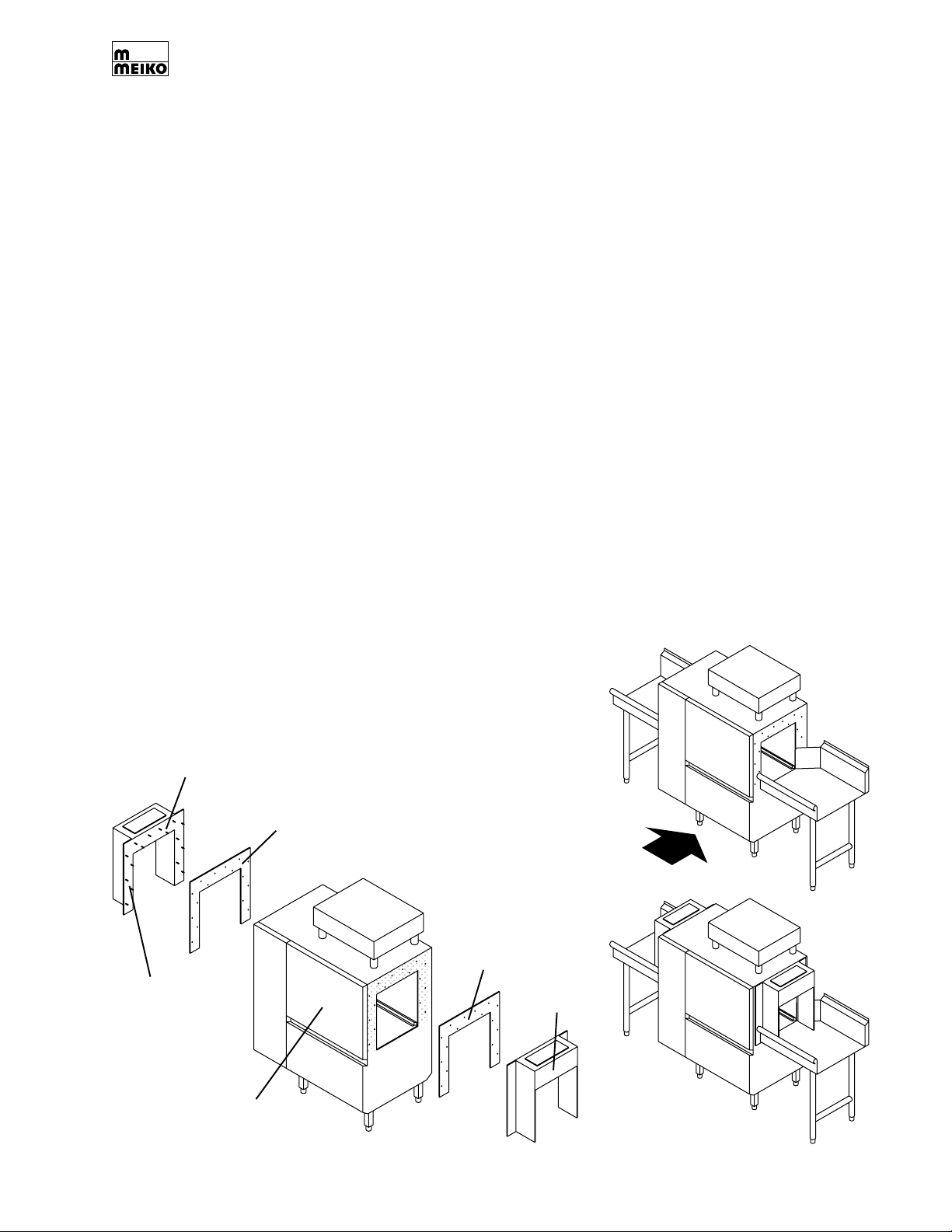
4. If dish tables are already in place, it may
be necessary to remove the end cowlings
to install the machine. To remove the cowlings, refer to Figure 3-1.
Each cowling is held in place by hex head
acorn nuts on the inside of the machine.
For easy access to the acorn nuts, simply
lift the front access door(s).
5. Using a spirit level, check that the appliance is level in both directions (front-toback AND side-to-side). If necessary, level
the appliance by rotating the bottom section of each foot.
CAUTION
The dishwasher MUST be level for proper
operation.
6. If you removed the cowling(s) in Step 4,
replace them onto the machine at this
time. Be sure to check that the rubber gasket that fits between each cowling and the
body of the machine is properly seated.
7. Run a fine bead of clear silicone sealant
along the top edge of the seam between
each cowling and the machine.
CAUTION
Do not attempt to slide the machine on its
feet. This can bend the legs.
Figure 3-1: Removing
Cowling
Threaded studs:
Qty. 16 for
standard height
machine
Qty. 20 for high-
hood (“-T” model)
machine
Open door(s) to
access acorn
nuts and washers
the end cowlings
(if required)
Gasket
With cowlings
removed, set
machine into
place between
tables
Gasket
Cowling
Replace cowlings
Page 5
SECTION 3 - INSTALLATION
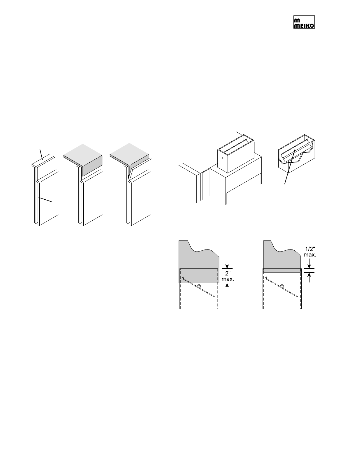
3.4 Tabling Attachment
1. Position the table lip-in at both ends of the
machine, as shown in Figure 3-2. Be sure
to seat the lip-in against the inner plate of
the sidewall of the dishwasher.
CAUTION
If the table lip-in is forced between the
inner and outer plates, it will not seat
properly. Always ensure that the lip-in is
seated correctly as shown in Figure 3-2.
Figure 3-2: Tabling attachment
Outer
plate
CORRECT INCORRECT
Table lip-in
extends to
Inner
plate
inside face of
inner plate.
Table lip-in
should not be
inserted
between inner
and outer plate.
3.5 Vent Cowl Collars (if so equipped)
For units that are not equipped with optional
vent cowl collars, skip ahead to Section 3.6,
“Booster Heater Placement.”
1. Check that the ventilation ducts (or “pant
legs” are correctly positioned above the
vent cowl collars on the machine.
2. Determine how the ducts will be attached.
See Figure 3-3.
Figure 3-3: Vent cowl collar ducting
Baffle
2. Position the dishwasher and tables as
follows:
• Check that the centerline at the open-
ing of each table is aligned with the
centerline of the rack track of the dishwasher.
• Check that the surface height of each
table matches the height of the rack
track of the dishwasher, to ensure a
smooth transition. The standard table
surface height is 34” (864mm).
• Check that the dishmachine is level.
The height of the dishmachine, and of
most tables, can be adjusted by rotating
the feet at the end of the legs.
CAUTION
After adjusting the height of the
dishmachine, always check that it is level
to ensure proper operation.
3. After the tables have been positioned
correctly, secure them to the dishwasher
using silicone sealant.
Page 6
DUCT SLEEVED
OUTSIDE COLLAR
(RECOMMENDED)
DUCT SLEEVED
INSIDE COLLAR
• In most instances, the ducts can be
sleeved over the outside of the vent cowl
collars. This is the easiest installation and
is recommended.
For this installation, the INSIDE
DIMENSIONS of the ducting, when
viewed from the front of the machine,
should be 4” W x 16” D. The duct can
overlap the outside of the vent cowl collar
by up to 2” without interfering with the
operation of the baffle.
SECTION 3 - INSTALLATION
• Where required by local codes, the ducts
can be sleeved inside the edge of the vent
cowl collars.
For this installation, the OUTSIDE
DIMENSION of the ducting, when viewed
from the front of the machine, should be
3-3/4”W x 15-3/4” D. The duct should
overlap the inside of the vent cowl collar
by a maximum of 1/2” to avoid interfering
with the baffle.
3. Install the ducts to the vent cowl collars.
4. Secure the ducts to the collars using silicone sealant.
5. The baffles cannot be properly adjusted
until the machine is turned on. Refer to
Section 3.17, “Final Assembly.”
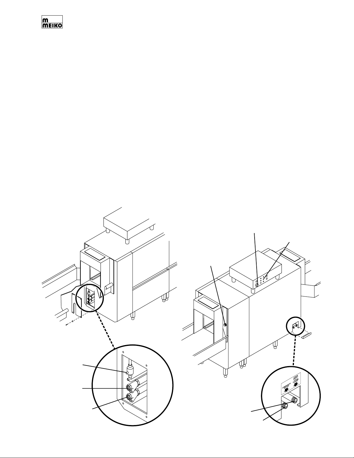
Figure 3-4: Accessing utility connections
3.6 Booster Heater Placement
For units that are not equipped with an external booster heater (for instance, when using
a building’s boiler as a 180°F water supply),
skip ahead Section 3.7, “Accessing the Utility Connections.”
The booster heater should be positioned at
the unload end of the machine, close to the
water inlet access panel. Meiko recommends
a maximum pipe length from the booster to
the machine’s water inlet of 48”. If a longer
pipe run is necessary, Meiko recommends the
use of pipe insulation to minimize heat loss.
3.7 Accessing the Utility Connections
The utility connections for the machine are
shown in Figure 3-4.
UNLOAD END
(VIEWED FROM
FRONT)
Rinse aid
connection
Remove
access
panel
LOAD END (VIEWED FROM REAR)
Machines without
prewash: Dummy plug in
wall for direct detergent
injection
Machines with prewash:
Pre-plumbed raceway
for detergent tubing
Main electrical
supply strain
relief
Additional holes for
detergent pump and
accessory wiring
(covered with blind
plugs)
Remove
access
panel
Hot (180°F) water
connection
Warm (110-140°F)
water connection (if
machine is equipped
with prewash)
UNLOAD END
(VIEWED FROM REAR-
STEAM HEATED
MACHINES ONLY)
Steam supply line (outboard)
Steam condensate return (inboard)
Page 7
SECTION 3 - INSTALLATION
3.8 Main Electrical Supply Connection
WARNING!
Check that the circuit breaker/fused
disconnect is in the OFF position and
that the unit is switched off before
making the electrical utility connections.
IMPORTANT
In some cases, local codes dictate that
electrical supply connections be made only
by a certified professional.
1. Check that the incoming power leads are
of sufficient rating for the appliance’s
current draw. Amperage and minimum
supply wire specifications are shown on
the serial plate and on the electrical information label on the control box.
2. Remove the top cover panel from the
electrical control box by removing the four
screws that hold it in place.
3. Locate the strain relief for the electrical
supply wiring on the back of the control
box (Figure 3-4). Thread the incoming
supply leads through the strain relief and
to the main electrical supply terminal block.
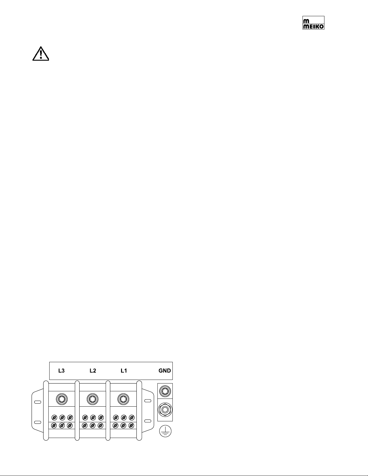
4. Refer to Figure 3-5 and the electrical wiring
diagram. Connect the power supply and
ground leads as indicated.
5. Adjust the strain relief to fasten the wiring
in place. You should leave enough slack
in the wiring to prevent stress on the
terminal connections.
Figure 3-5: Main electrical supply
connections
L1, L2 and L3 = “hot” (line)
GND = ground
3.9 Dispensing System Overview
K-Series rack conveyor dishwashers are
designed for use with a liquid rinse additive,
and either solid or liquid detergents. Detergent
and rinse additive injection is supplied by
external dispensing systems (supplied by
others).
The machine is equipped with:
• A location for detergent injection at the
load end of the machine (see Figure 3-6).
- Machines equipped with a prewash
section (K-66, K-76, K-80, K-86, K-90,
K100) have a pre-plumbed tubing
raceway exiting the machine at this
location. The raceway is routed to deliver
detergent into the wash tank. Solid or
liquid detergent lines can be routed
down the raceway and into the tank.
- Machines that are NOT equipped with
a prewash section (K-44, K-54,
K-64), have a dummy plug at this
location. Removal of the plug allows
the detergent line to be installed for
direct chemical injection into the wash
tank at this location.
• A dummy plug in the floor of the wash tank
that permits the installation of a detergent
concentration probe.
• A final rinse plenum chamber with a fitting
for a liquid rinse aid line (see Figure 3-7).
A threaded pipe connection just below the
plenum allows the installation of a final
rinse pressure switch.
A dispensing system terminal block inside the
control box of the machine provides contacts
for two line voltage relays. These relays,
when closed, provide a “window” for external
pump systems to activate.
Page 8
• A relay labeled “DDC” (Detergent
Dispenser Connection) closes whenever
the wash pump is in operation. This relay
should be used for the detergent dispenser.
• A relay labeled “CVS” (Conveyor Voltage
Signal) closes whenever the conveyor
drive motor is in operation. This relay
should be used for the rinse aid dispenser.
 Loading...