

Meiko CS70 Installation Manual
MODEL CS 70
Door-Type Low Temperature Chemical Sanitizing Dishwasher
OWNER’S INSTALLATION, OPERATION AND
MAINTENANCE MANUAL
MEIKO • 1349 Heil Quaker Blvd. • La Vergne, TN 37086 • Phone: (615) 399-6600 • (800) 55-MEIKO • Fax: (615) 399-6620
Rev . 7/14
TABLE OF CONTENTS
1. INTRODUCTION ................................. 3
1.1 Overview of Equipment ............................. 3
1.2 General Safety Information........................ 3
2. TRANSPORT AND SHIPPING ............ 3
3. INSTALLATION.................................... 4
3.1 Overview of Installation ............................. 4
3.2 Requirements Before Installation .............. 4
3.3 Uncrating, Positioning and Leveling ............. 5
3.4 Accessing the Utility Connections ............. 5
3.5 Main Electrical Supply Connection............ 6
3.6 Dispensing System Overview.................... 7
3.7 Connecting Chemical Containers.............. 7
3.8 Fresh Water Supply Connection................ 8
3.9 Drain Connection....................................... 9
3.10 Tabling Attachment.................................. 10
3.11 Final Assembly ........................................ 12
3.12 Priming the Liquid Detergent, Rinse Aid
and Sanitizer Lines.................................. 12
3.13 Checking for Correct Chemical
Concentration.......................................... 13
4. PROGRAMMING ................................14
5. OPERATION.......................................15
5.1 Location and Description of Controls....... 15
5.2 Startup..................................................... 16
5.3 Loading....................................................16
5.4 Operation................................................. 17
5.5 Between Cycles....................................... 17
5.6 Shutdown ................................................ 17
6. CLEANING .........................................18
6.1 Daily Cleaning (or as required)................ 18
6.2 Weekly Cleaning (or as required)............ 18
6.3 Exterior Cleaning (as required)................ 19
6.4 Deliming (as required) ............................. 19
7. TROUBLESHOOTING........................20
8. PARTS LISTING .................................26
9. WIRING DIAGRAMS ..........................43
9.1 Ladder schematic, 115V/60Hz/1Ph ......... 43
AN ELECTRICAL WIRING DIAGRAM IS LOCATED INSIDE
THE COVER OF THE CONTROL BOX OF THIS MACHINE.
THE MEIKO MODEL CS 70 DISHWASHER HAS BEEN DESIGNED
EXCLUSIVELY FOR THE WASHING OF DISHES, GLASSWARE, CUTLERY
AND KITCHEN UTENSILS IN A COMMERCIAL OR INSTITUTIONAL SETTING
AND MUST NOT BE USED FOR ANY OTHER PURPOSE.
MEIKO ACCEPTS NO RESPONSIBILITY FOR DAMAGE TO THE APPLIANCE, SURROUNDING
EQUIPMENT OR ENVIRONMENT THAT IS CAUSED BY INAPPROPRIATE INSTALLA TION OR
OPERA TION, OR FROM ANY SERVICE THAT IS UNDERTAKEN BY NON-AUTHORIZED
PERSONNEL, OR FROM THE USE OF ANY PARTS EXCEPT THOSE THAT ARE APPROVED BY THE
MANUFACTURER. ANY SUCH INSTALLATION, USE OR SERVICE WILL IMMEDIATELY VOID THE
MANUFACTURER’S WARRANTY.
ANY MODIFICATIONS T O THE APPLIANCE THAT ARE PERFORMED WITHOUT THE WRITTEN
PERMISSION OF MEIKO WILL IMMEDIATELY VOID THE MANUFACTURER’S WARRANTY.
MEIKO reserves the right to change any specifications without notice at any time.
© 2014 MEIKO USA, Inc. All rights reserved.
MEIKO • 1349 Heil Quaker Blvd. • La Vergne, TN 37086
Phone: (615) 399-6600 • (800) 55-MEIKO • Fax: (615) 399-6620
www.meiko.us
Page 2
SECTION 1 - INTRODUCTION
1INTRODUCTION
1.1 Overview of Equipment
The MEIKO Model CS 70 kube is a
commercial dishwasher designed for cleaning
dishes, glassware, trays, cutlery and kitchen
utensils with a minimum of employee
intervention or supervision.
A control keyp ad allows easy selection of On/
Fill and Off/Drain cycles. A digital display
permits easy monitoring of operation.
Other features of the unit that affect operation
include:
CS 70 - advanced microprocessor technology
for maintenance and end user dishmachine
settings
Auto Prime - Timed priming function on all
chemical pumps
Temp Safe - User-selectable temperaturebased automatic drain/refill feature to ensure
desired wash and rinse temperatures
Delime Cycle - Automatically fills machine,
signals for delimer, delimes for five minutes,
then drains and rinses machine
Fully automatic operation - automatic fill,
automatic start, and automatic drain
Proof of delivery window - provides a visual
indication that chemicals are being dispensed
For efficient and SAFE operation, be sure to
follow the installation and operating
instructions provided in this manual. In
particular, all safety symbols and notices on
the equipment and in the supplied
documentation must be followed.
IMPORTANT
The Model CS 70 kube dishwasher has been
designed exclusively for the washing of
dishes, glassware, trays, cutlery and kitchen
utensils in a commercial or institutional setting
and must not be used for any other purpose.
1.2 General Safety Information
The following symbols and headings are used
throughout this manual to indicate possible
hazards to persons or to the equipment. The
symbols and headings are shown in order of
importance. The descriptive text following these
headings is italicized for easy recognition.
WARNING! Possible hazard to per-
sons, such as from electrical shock, crushing, or
hot surfaces.
CAUTION Possible hazard to the
dishwasher or to other
equipment.
IMPORTANT Vital information or tips for
the installer or operator.
NOTE Information or tips for the
installer or operator.
2TRANSPORT AND SHIPPING
IMPORTANT
• Observe any notices on the crating
material that pertain to shipping.
• Use care when transporting the equipment.
• Customers are required to inspect all
equipment upon receipt for freight
damage, concealed or otherwise. If a shipment is signed for without noting freight
damage, the receiving firm accepts all
responsibility, and MEIKO cannot collect
for a future discovery of freight damage.
If equipment arrives at the customer’s
site with crate and/or package damage,
the factory strongly suggests refusal
of the shipment due to damage claim.
Immediately contact MEIKO Customer
Service at 1-800-55-MEIKO (1-800-556-
3456), providing full details on the
customer, serial number and extent of
damage present.
WARNING!
In NO EVENT should a damaged
appliance be installed or operated!
Page 3

SECTION 3 - INSTALLATION
3INSTALLATION
3.1 Overview of Installation
The owner should contract with qualified
personnel to move the appliance to the
installation location, unpack it, and prepare it
for final utility connections. In most cases,
local codes prevent the final utility connections
from being made by any party other than a
licensed electrician and/or plumber.
IMPORTANT
It is the responsibility of the owner to ensure
that all aspects of the installation comply with
all applicable local and national codes.
IMPORTANT
The appliance’s warranty is not valid until a
MEIKO Authorized Service Agent performs a
Startup and Demonstration on the appliance.
This Demonstration should be scheduled after
installation.
Installation of the dishwasher involves the
following steps:
• Verifying that the utility connections are
present, are appropriate for the appliance,
and comply with all applicable local and
national codes.
• Unwrapping the appliance (leaving the
shipping skid in place for easier movement) and checking for shipping damage.
• Moving the appliance to the installation
location, removing the skid, and leveling
the feet.
• Connecting the electrical supply.
• Connecting the warewasher’s detergent,
rinse aid and sanitizer tubes to appropriate
dispensers.
• Connecting the fresh water supply.
3.2 Requirements Before Installation
Before the installer can uncrate and move the
appliance to the installation location, the
following conditions MUST be met:
• INST ALLATION AREA REQUIREMENTS
- The area MUST be frost-free. Freezing
temperatures (32°F/0°C or lower)
inhibit proper operation and can
damage internal components.
- The area MUST have a firm floor
surface. It is possible to compensate
for uneven flooring by adjusting the
feet.
- The area should be away from
appliances, furniture or surfaces that
can be damaged by water . If this is not
possible, these items should be
protected from the small quantities of
water that are splashed during normal
operation of the dishwasher.
• UTILTITY CONNECTION REQUIREMENTS
- Connections must be present and
ready for hookup to the appliance. All
utility supplies must comply with the
electrical information labels, with the
information on the data plate, and with
all applicable local and national codes.
- Electrical leads and the water supply
line (supplied by the customer) must
be present.
- Appropriate detergent, rinse aid and
sanitizer containers should be installed
and ready for connection to the
appliance.
• GENERAL REQUIREMENTS
Authorized personnel should be available
to perform the actual utility connections.
• Connecting the accumulator drain.
• Connecting the machine to tabling.
• Contacting your MEIKO Authorized
Service Agent to perform a Startup and
Demonstration on the appliance. This step
also validates the appliance’s warranty.
Page 4
SECTION 3 - INSTALLATION
3.3 Uncrating, Positioning and Leveling
1. Remove all shipping and packaging material
from the appliance, including supports and
wrappings. Leave the shipping skid in place at
this time to allow for easier movement to the
installation location.
2. Check for shipping damage as described in
Section 2, “Transport and Shipping.” If damage
is present, immediately contact MEIKO
Customer Service at 1-800-55-MEIKO (1-800-
556-3456), providing full details on the
customer, serial number and extent of damage
present.
3. Move the appliance to the installation area and
remove the skid. Use caution to avoid damaging
the appliance or any of its components.
4. Using a spirit level, check that the appliance is
level in both directions (front-to-back AND sideto-side). If necessary, level the appliance by
rotating the bottom section of each foot.
Figure 3-1
Remove 2
screws
CAUTION
The dishwasher MUST be level for proper
operation.
3.4 Accessing the Utility Connections
Water supply and drain connections are accessed
from the lower right side of the dishwasher. The
electrical supply enters through a strain relief at
the back of the control box. The terminal block is
located inside the control box.
To open the control box:
1. Remove AND RETAIN the two screws on the
top edge of the cover panel. See Figure 3-1.
2. Swing the cover panel down to access the
interior of the box. The main electrical supply
terminal block is located on the back wall of
the box.
Figure 3-2
Swing panel
down to access
interior of box
Main electrical
supply terminal
block
Page 5
SECTION 3 - INSTALLATION
3.5 Main Electrical Supply Connection
WARNING!
Check that the circuit breaker/fused
disconnect is in the OFF position and
that the unit is switched off before
making the electrical utility connections.
IMPORTANT
In some cases, local codes dictate that
electrical supply connections be made only
by a certified professional.
1. Check that the incoming power leads are
of sufficient rating for the appliance’s
current draw. Amperage and minimum
supply wire specifications are shown on
the serial plate and on the electrical
information label.
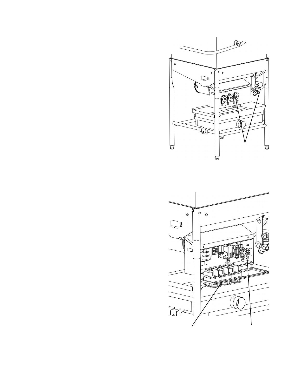
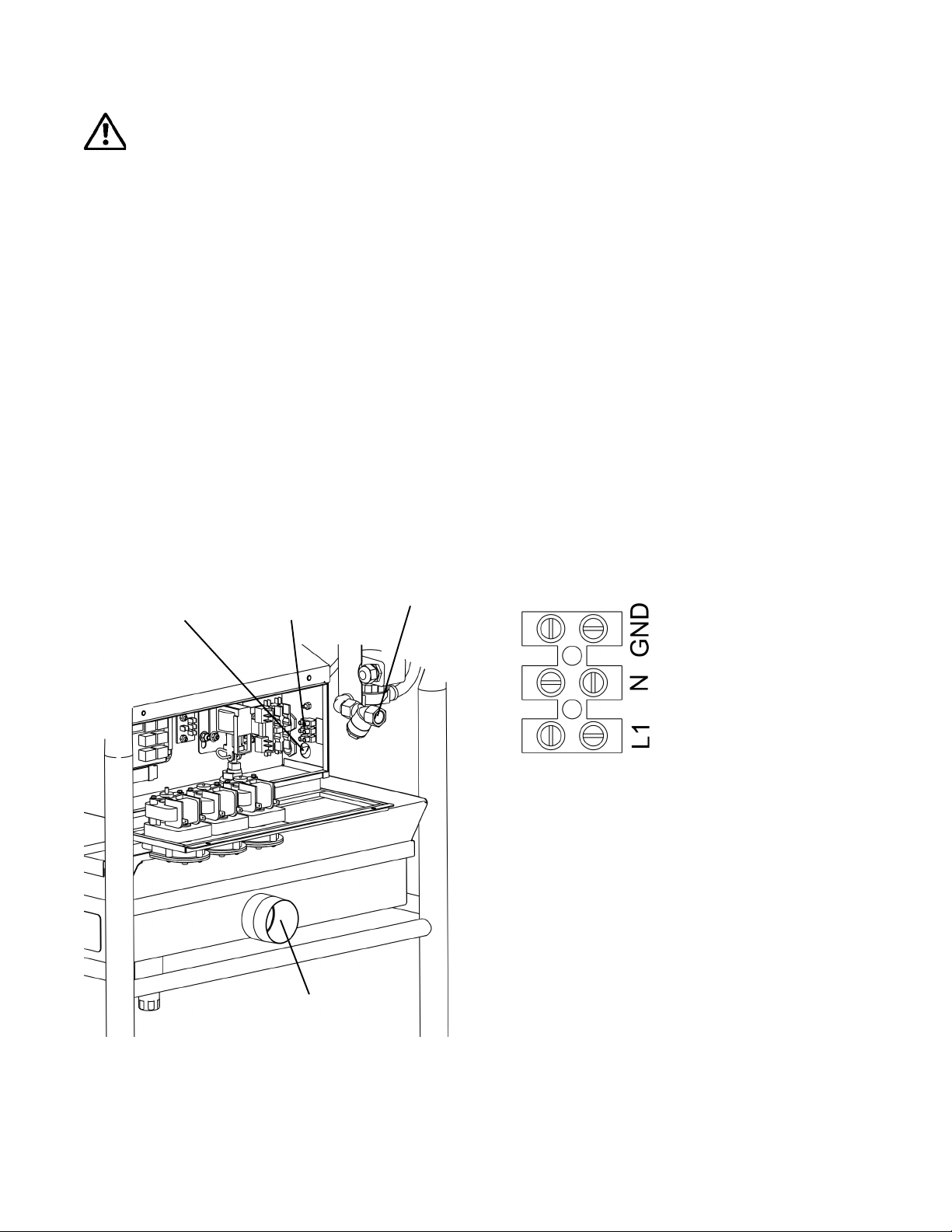
Figure 3-3: Utility connections
2. Check that the incoming power leads are
long enough to permit the unit to be
repositioned for servicing.
3. Locate the strain relief for the electrical
supply wiring at the lower rear of the
control box (Figure 3-3). Thread the
incoming supply leads through the strain
relief and to the main electrical supply
terminal block on the back wall of the box.
4. Refer to Figure 3-4 and the electrical wiring
diagram. Connect the power supply and
ground leads as indicated.
5. Adjust the strain relief to fasten the wiring
in place. You should leave enough slack
in the wiring to prevent stress on the
terminal connections.
Figure 3-4: Main electrical
supply connections
Electrical
supply
strain relief
Main electrical
supply terminal
block
Drain
Fresh water
connection
115V, 60 Hz, 1 Phase:
L1 = “hot” (line)
N = neutral
GND = ground
Page 6
ECTION 3 - INSTALLATION
S
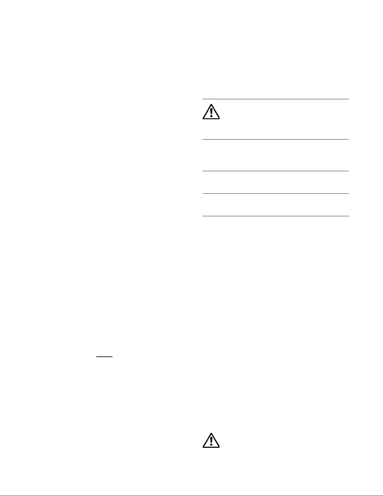
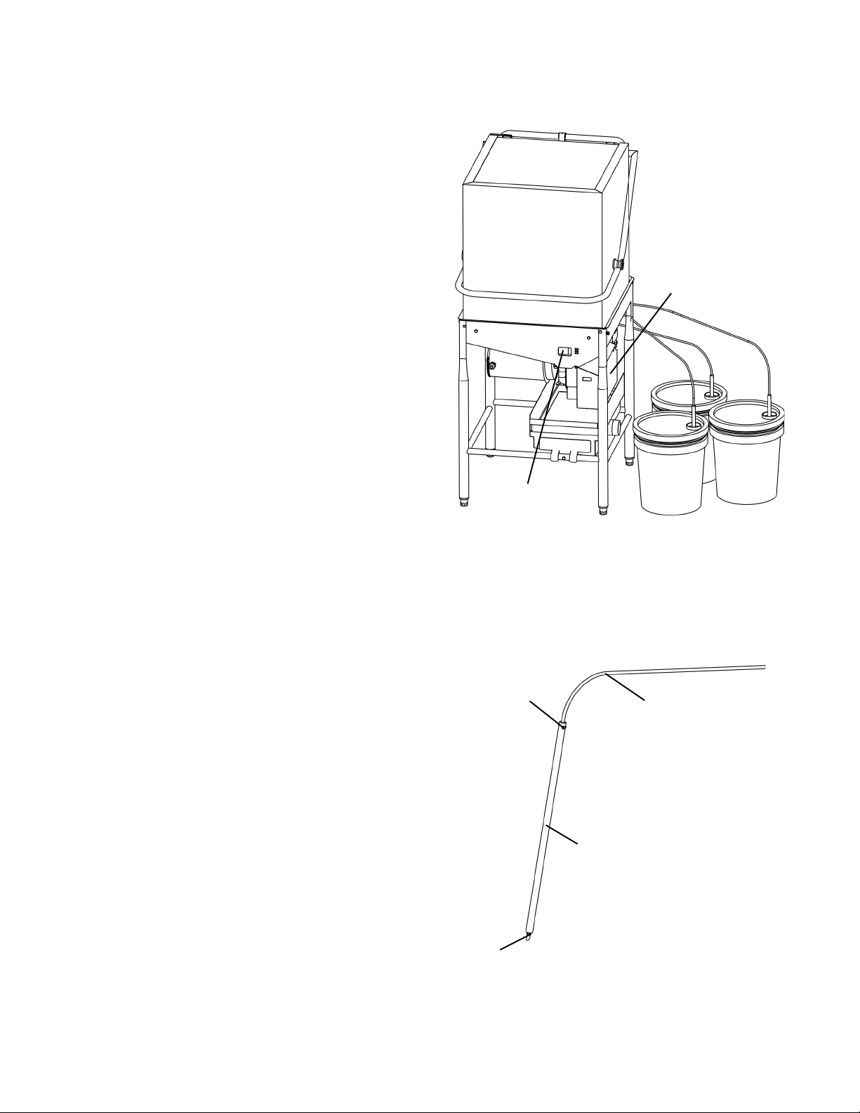
3.6 Dispensing system overview
The CS 70 is equipped with liquid detergent,
rinse aid and sanitizer pumps. Each pump is
equipped with a supply tube that exits the rear
of the machine. A stiffener tube is also
provided for the ends of each tube. The end
of the tube with the stiffener should be
inserted and fastened into appropriate liquid
chemical containers (supplied by others).
During operation, chemicals are automatically
dispensed according to the timed settings for
each pump, which can be individually
configured as required. A proof of delivery
window provides a visual indication that
chemicals are being dispensed.
See Figure 3-5.
3.7 Connecting Chemical Containers
1. Check that all chemicals are compatible
with the unit. In particular, a commercial
(not a domestic) detergent MUST be used.
2 Check that the containers are correctly
installed or positioned according to the
manufacturer’s instructions.
3. Each chemical dispensing pump is
equipped with a supply tube that exits the
rear of the machine. A stiffener tube is also
provided for the end of each tube.
4. Assemble a stiffener tube onto the end of
each of the chemical tubes using two tie
wraps. See Figure 3-6.
5. Locate the RED liquid detergent tube,
marked DET. Insert the tube stiffener into
the liquid detergent container and fasten
it in place.
Figure 3-5: Dispensing
system components
Chemical
pumps are
inside
control box
Proof of
delivery
window
Chemical
containers
Figure 3-6: Assembling the
stiffener tubes
Tie
wrap
Flexible tube
(from rear of
machine)
6. Locate the BLUE liquid rinse aid tube
marked RIN. Insert the tube stiffener into
the liquid rinse aid container and fasten it
in place.
7. Locate the CLEAR or WHITE liquid
sanitizer tube marked SAN. Insert the tube
stiffener into the liquid sanitizer container
and fasten it in place.
Stiffener
tube
Tie
wrap
Page 7
SECTION 3 - INSTALLATION
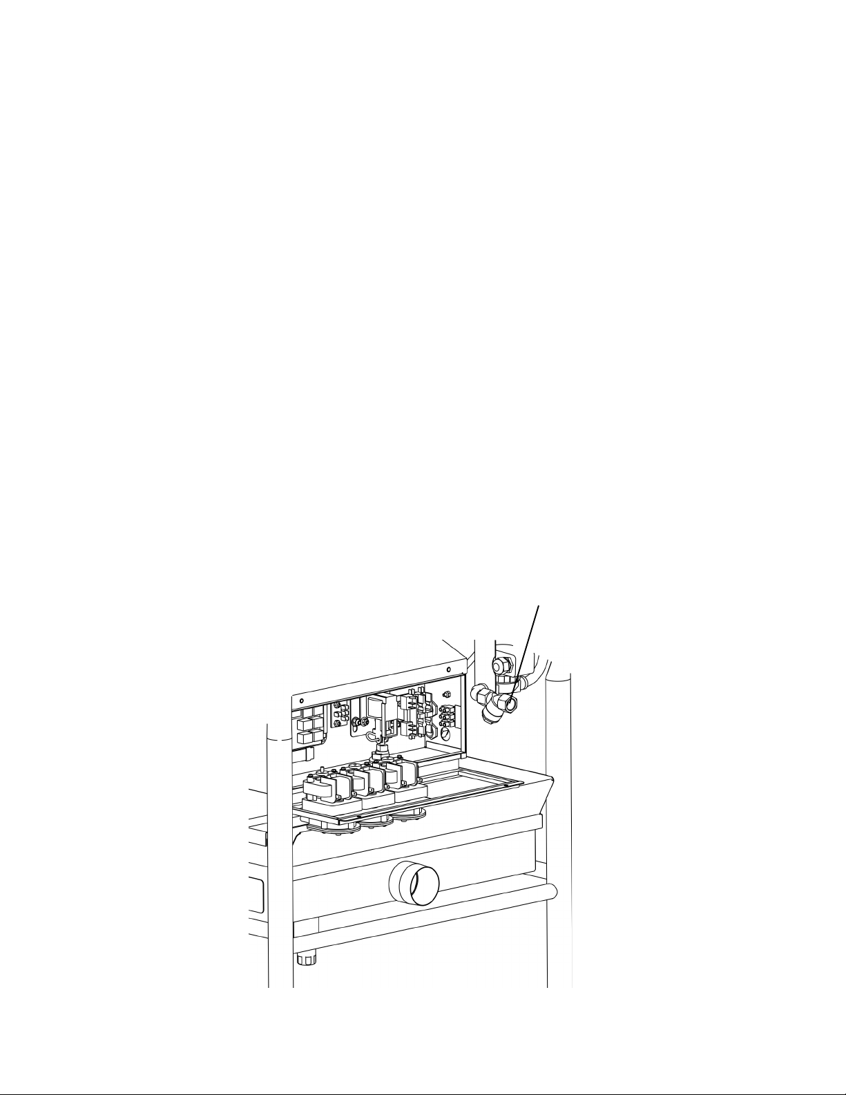
3.8 Fresh Water Supply Connection
CAUTION
Before connecting the water supply, the line
MUST be flushed clean of all debris, including
(but not limited to) pipe sealant, metal
particles, solder, etc. This debris can damage
the appliance.
IMPORTANT
In some cases, local codes dictate that water
supply connections be made only by a
certified professional.
1. Check that iron or other metal particles
cannot contaminate the fresh water
supplied to the dishwasher.
2. Check that the incoming water pressure
is within the acceptable range for the
appliance (maximum 100 psi, 6.89 bars).
3. Check the incoming water temperature.
MEIKO recommends a water temperature
of 140°F/60°C for optimum operation.
4. Check the incoming water hardness.
MEIKO recommends a hardness of 4-6
grains per U.S. gallon.
5. Because the water inlet incorporates a “Y”
strainer, an additional “Y” strainer in the
water supply is unnecessary unless
required by local, national or international
codes.
6. Connect the customer-supplied water line
to the street elbow fitting on the fill
assembly . Use a sealing compound on the
threads to ensure that no leaks are present
in the connection. See Figure 3-7.
7. Check that the water line is long enough
to permit the unit to be repositioned for
servicing.
Figure 3-7: Fresh water connection
Fresh water
connection
Page 8
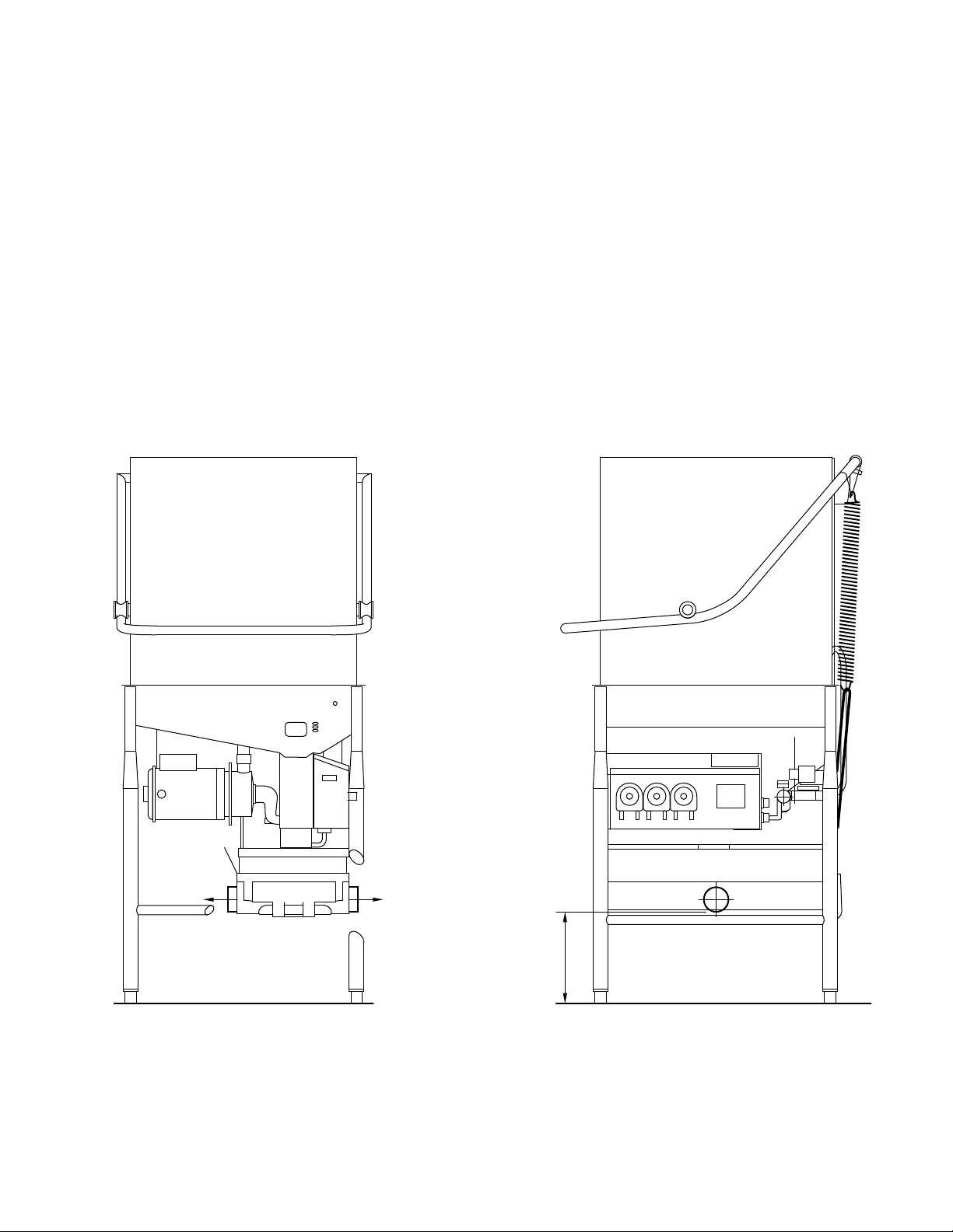
3.9 Drain Connection
ECTION 3 - INSTALLATION
S
1. Check that the floor drain is correctly sized
for the machine. A drain with a minimum
diameter of 2”/51mm is strongly
recommended.
2. Check the type of drain that will be used.
(wall or floor).
CAUTION
The CS 70 uses a gravity drain system.
No portion of the drain system may be
higher than 10-1/2” (267mm) A.F.F. to
ensure correct drain operation. See Figure
3-8.
Figure 3-8: Drain configuration and connection
3. Check the position of the machine drain
in reference to the intended facility drain.
If required, the drain pan can be removed
and reversed to change the position of the
drain. See Figure 3-8.
4. Route the drain line to the drain. In some
cases, a grease trap (supplied by others)
must be fitted into the waste water line. If
this trap is required for your installation,
check that it is present.
D
1
Drain faces
LEFT from
factory
If required,
remove and
reverse drain
pan so drain
faces RIGHT
D
2
No portion of
the drain
system may
be higher
than 10-1/2”
(267mm)
A.F.F.
10 1/2"
(267mm)
max. AFF
Page 9
SECTION 3 - INSTALLATION
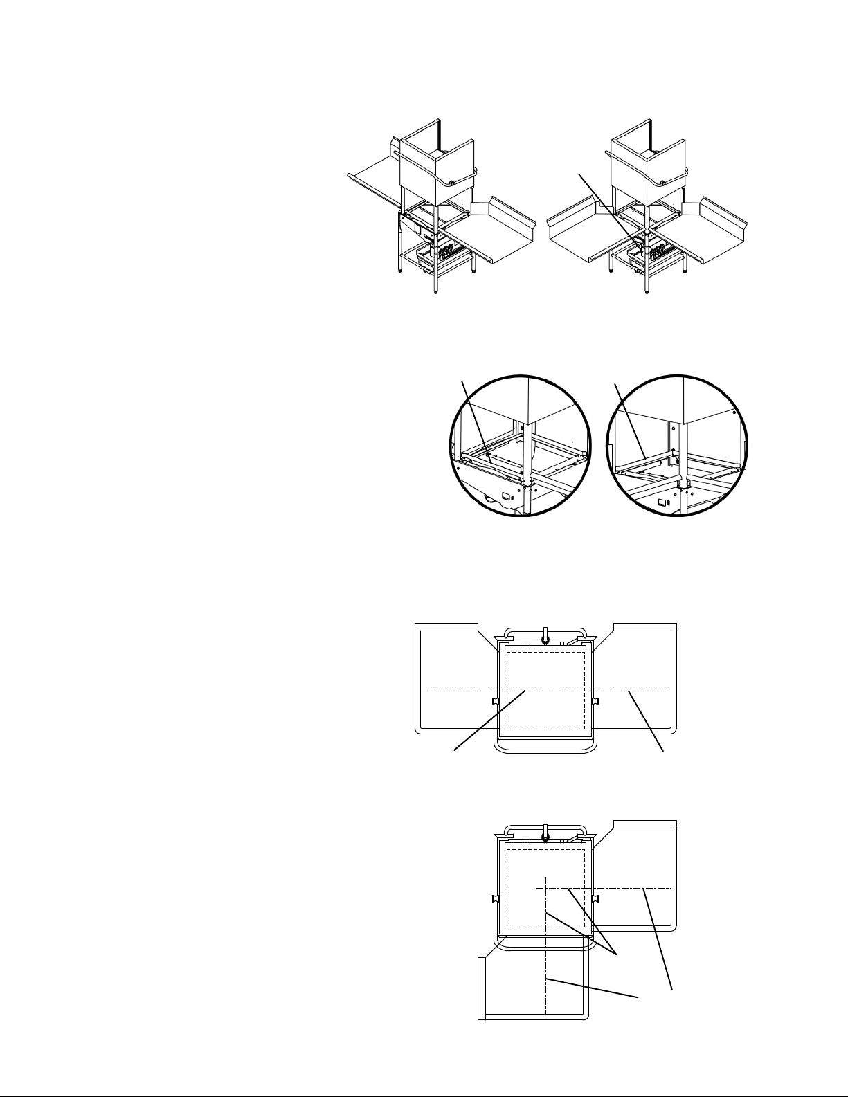
3.10 T abling Att achment
The CS 70 can be positioned in
either of two tabling configurations;
straight through, or in a corner
installation. See Figure 3-9.
1. IF the machine will be
positioned in a corner, perform
the following steps before
attaching the tables:
• Position the machine so that
the LEFT REAR corner of
the machine faces the
corner of the wall, as shown
in Figure 3-9. For corner
installations, this placement
is necessary to ensure that
the control panel can be
reached by the operator.
• Remove the FRONT rack
guide as shown in Figure 3-
9. The guide is held in place
by two screws. Replace the
guide on the LEFT SIDE
position in the 2 mounting
holes provided.
2. Position the machine and tables
as follows:
Figure 3-9: Straight-through and
corner tabling configurations
Control
panel
Straight-through
Before After
For a corner
installation ONLY,
move the rack rail
guide from the
FRONT position to
the LEFT SIDE
position.
Corner installation:
Left rear corner of machine
MUST face corner of wall to
ensure access to control panel.
Figure 3-10: Aligning the t able centerlines
with the dishmachine
• Check that the centerline of
the opening at the end of
each table is aligned with
the centerline of the rack
track of the machine. See
Figure 3-10.
• Check that the surface
height of each table
matches the height of the
rack track of the machine,
to ensure a smooth transition. The standard table surface height is 34” (864mm).
• Check that the machine is
level.
Page 10
Centerline of
rack track
Straight-through installation
Corner installation
Centerline
of rack track
Centerline of
table opening
Centerline of
table opening
FRONT OF
CS 70
SECTION 3 - INSTALLATION
The height of the machine, and of most
tables, can be adjusted by rotating the feet
at the end of the legs.
CAUTION
After adjusting the height of the machine,
always check that it is level to ensure
proper operation.
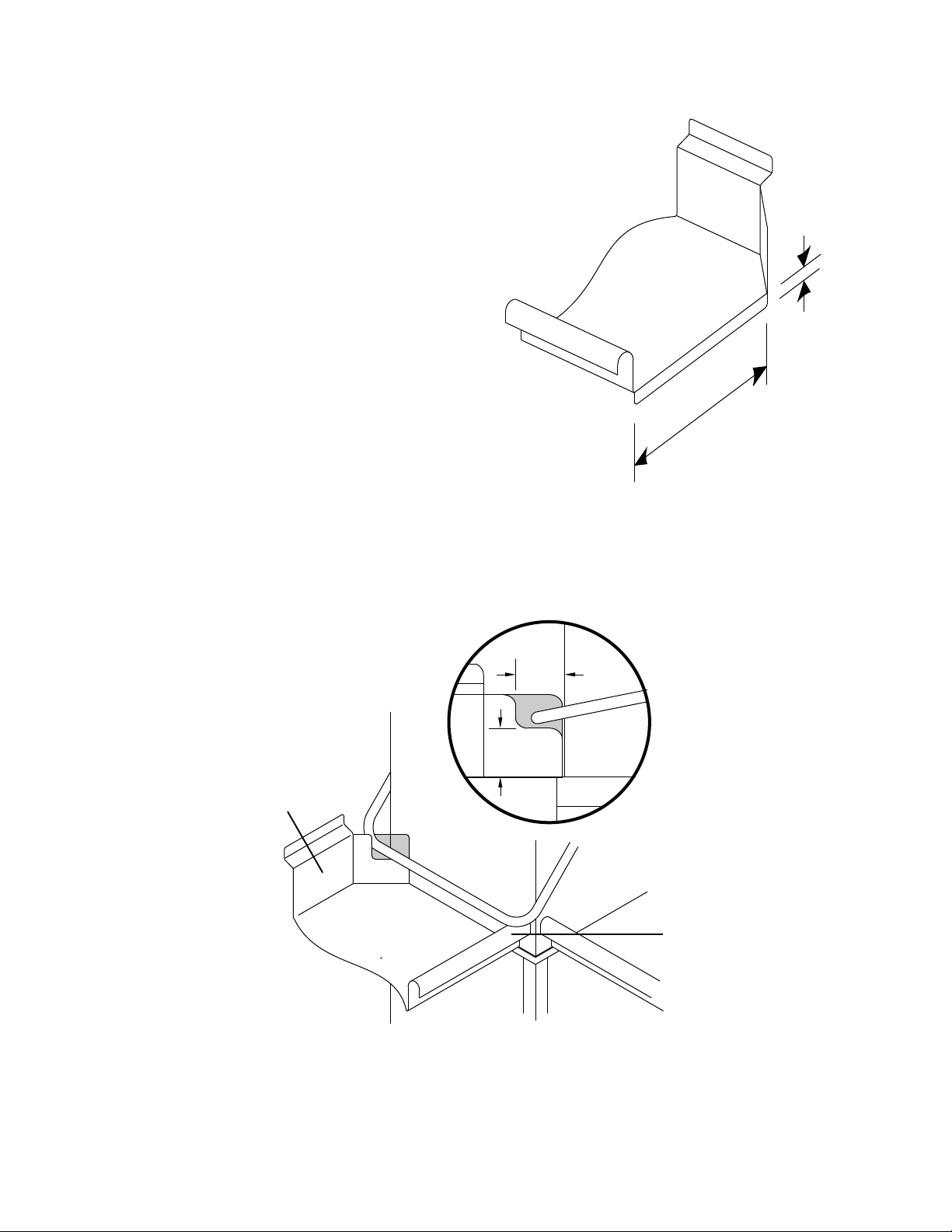
3. Position each table lip-in at the machine.
Be sure to seat the lip-in against the inner, vertical mounting surface. The lip-in
flange should be no more than 1” in height
as shown in Figure 3-11.
4. For corner installations, check that the
sides of the front table do not interfere with
the door handle when the door is closed.
If it is necessary to trim the table sides to
clear the handle, refer to Figure 3-12.
5. After the tables have been positioned
correctly, secure them to the machine
using silicone sealant.
Figure 3-11: Tabling attachment
Turndown
lip-in
flange
1” (25mm)
max.
20-1/4”
(515mm)
recommended
Figure 3-12: Door handle clearance for corner installations
(127mm), cut out as
shown to clear door
Backsplash
If backsplash is
higher than 5”
hande.
5" (127mm)
from front
of door
panel
5" (127mm)
max
Front-side cutout is
only necessary if
top of rolled edge is
more than 5”
(127mm) above
tabletop.
NOTE
An optional false panel is available to prevent splashing onto the walls or floor. The false
panel may be used with either straight-through or corner tabling configurations. Mounting
instructions are provided with the false panel. Contact MEIKO Customer Service at
1-800-55-MEIKO (1-800-556-3456) to order.
Page 11
ECTION 3 - INSTALLATION
S
3.11 Final Assembly
1. Check and tighten all electrical terminal
screws.
2. Replace the control box cover panel and
fasten in place with its two screws (Figure
3-1).
3. Switch the circuit breaker/fused
disconnect to the ON position. Be sure to
prime the chemical pumps and check for
correct chemical concentration before
operating the unit.
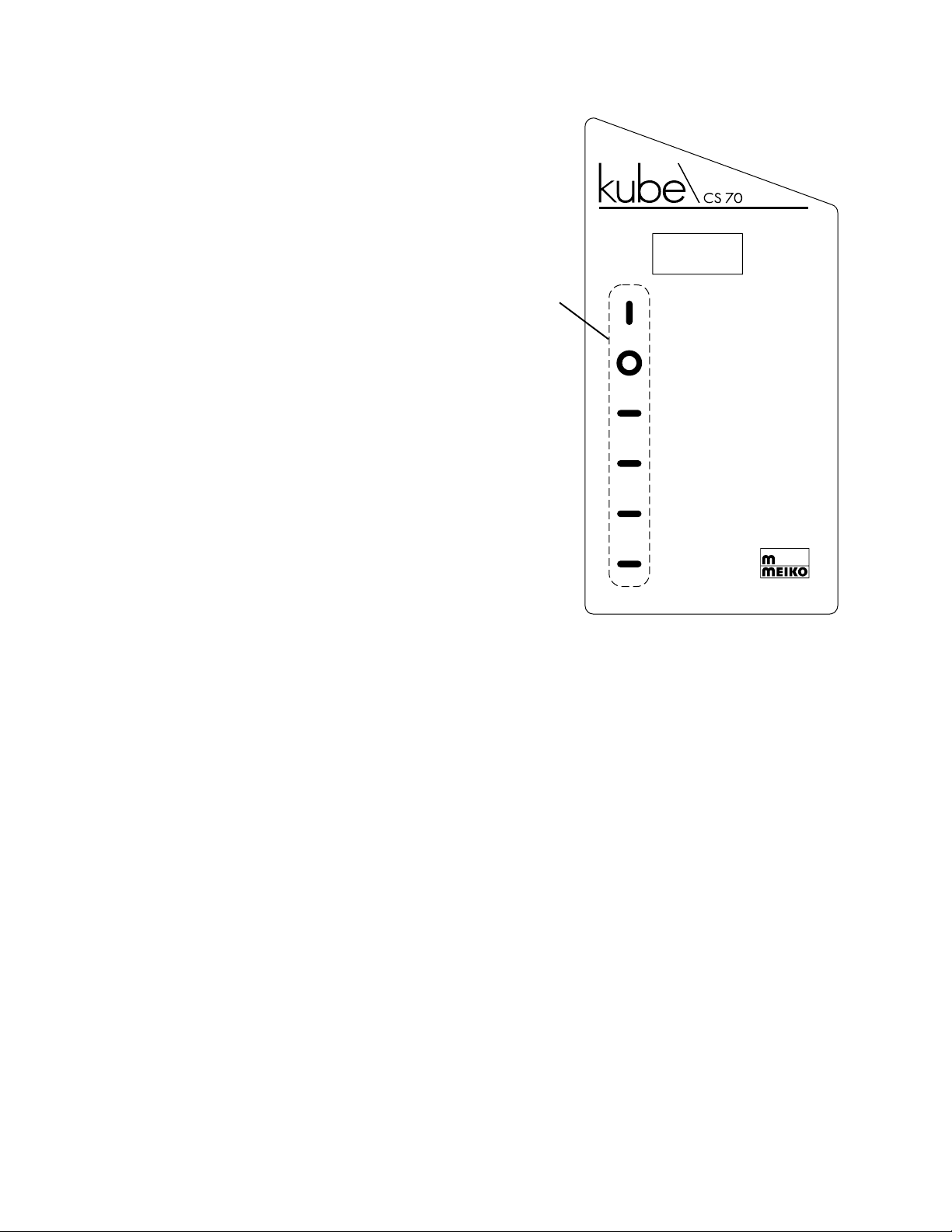
3.12 Priming the Liquid Detergent, Rinse
Aid and Sanitizer Lines
The chemical supply lines must be primed
before operating the unit. Keys are provided
on the control panel for this purpose. The
active area for each key is the symbol just to
the left of the text description. See Figure 3-
13.
1. Turn the machine on by pressing the ON/
FILL button.
Figure 3-13: kube\CS 70 control panel
MIN. 120° F / 49°C
Always press the
keys to the left of
the text (not the
text itself)
ON / FILL
EN MARCHE / REMPLIR
ENCENDIDO / LLENADO
OFF / DRAIN
ARRÊT / ÉVACUER
APAGADO / DRENAJE
DELIME
DÉTARTRER
DESCALCIFICAR
DETERGENT
DÉTERGENT
DETERGENTE
RINSE AID
AGENT DE RINÇAGE
ADITIVO DE ENJUAGUE
SANITIZER
DÉSINFECTANT
DESINFECTANTE
2. Prime the detergent pump. Press the
DETERGENT key twice, rapidly. The
pump will prime for 40 seconds and
automatically turn off.
3. Prime the rinse aid pump. Press the
RINSE AID key twice, rapidly. The pump
will prime for 5 minutes and automatically
turn off.
4. Prime the sanitizer pump. Press the
SANITIZER key twice, rapidly. The pump
will prime for 40 seconds and
automatically turn off.
5. If necessary, the pumps can be manually
primed for any length of time desired by
holding down the appropriate button.
Page 12

SECTION 3 - INSTALLATION
3.13 Checking for Correct Chemical
Concentration
The normal factory settings for chemical
injection are:
• Detergent - 0.256 oz. per gallon of wash
water (2.0 ml per liter).
• Rinse additive - 0.0256 oz. per gallon of
rinse water (0.2 ml per liter).
• Sanitizer - titrated using sodium
hypochlorite (NaClO) to 50 ppm minimum.
Other chemical sanitizing solutions
(iodine, etc.) may be used if permitted by
local, national and international codes.
• These settings are factory defaults, but all
settings used should always be checked
to ensure proper operation.
T o check if the normal settings are correct for
your chemicals, RUN THREE EMPTY
LOADS to completely cycle the water supply
and obtain accurate test results. This will only
take a few minutes. Then, run a sample load
with soiled ware and examine the results.
IMPORTANT
In all cases, any adjustments of the chemical
injection settings are to be performed either
by a chemical leasing company professional,
or by a MEIKO authorized service agent.
Changes by unauthorized personnel may void
your warranty.
If you need to contact your Authorized Service
Agency, please contact MEIKO Technical
Support at 1-800-868-3840.
• If the detergent setting is too low , the ware
will not be adequately cleaned.
• If the rinse aid setting is too low, spotting
or streaking may occur on the ware.
• The sanitizer setting should be confirmed
by the chemical leasing company
professional using an approved method
(typically test strips are used).
• If too much detergent or rinse aid is added,
the extra chemicals will be wasted. This
is often difficult to detect except by
determining how long your chemical
supplies last. If the chemicals are being
exhausted quickly , you may need to have
the chemical concentration adjusted.
• If it is necessary to adjust any of the
chemical injection settings, refer to
Section 4, Programming for instructions.
Page 13
SECTION 4 - PROGRAMMING
4PROGRAMMING
Before operating the machine, it may be
necessary to access the programming mode
of the CS 70 controller to select the desired
options and adjust the chemical concentration.
WARNING!
It is possible to select settings in
programming mode that may result in
ware that is not correctly washed or
rinsed. Always ensure that correct
settings are selected!
To access programming mode:
1. Check that the circuit breaker/fused
disconnect is in the ON position.
2. Check that the machine is turned OFF. If
necessary press the OFF/DRAIN key and
wait for the machine to drain.
3. Press and hold the SANITIZER button
until the machine enters programming
mode.
NOTE
If the machine is not turned off first,
pressing the SANITIZER button will simply
prime the sanitizer pump. It is not possible
to enter programming mode with the
machine already turned on.
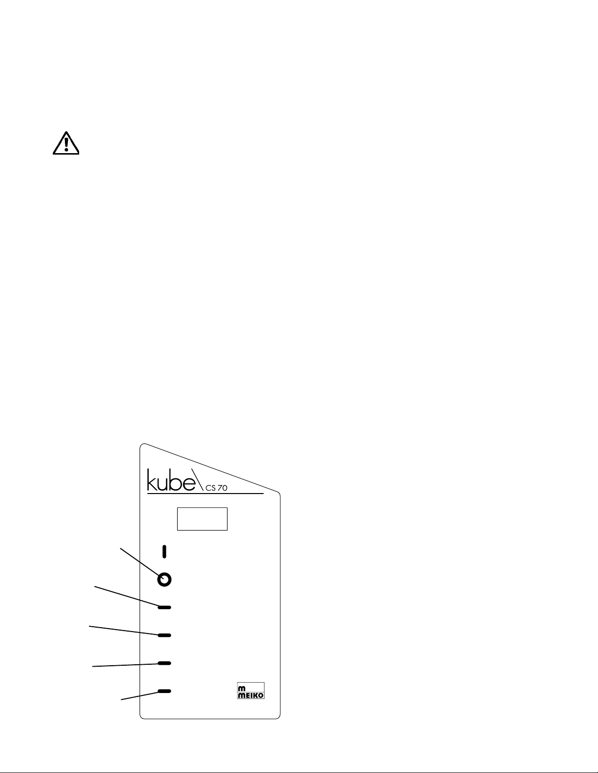
Figure 4-1:
Control panel
in
programming
mode
Toggle to
previous
function
Toggle to
next
function
Toggle to
previous
value
Toggle to
next
value
Save
changes
and exit
Page 14
MIN. 120° F / 49°C
ON / FILL
EN MARCHE / REMPLIR
ENCENDIDO / LLENADO
OFF / DRAIN
ARRÊT / ÉVACUER
APAGADO / DRENAJE
DELIME
DÉTARTRER
DESCALCIFICAR
DETERGENT
DÉTERGENT
DETERGENTE
RINSE AID
AGENT DE RINÇAGE
ADITIVO DE ENJUAGUE
SANITIZER
DÉSINFECTANT
DESINFECTANTE
Once the machine is in programming mode:
• Press the OFF/DRAIN and DELIME keys
to scroll up and down through the functions.
• Press the DETERGENT and RINSE AID
keys to change the value/state shown.
• Press the SANITIZER key again to save
changes and exit programming mode. The
machine will then drain and turn off.
The programmable functions available are:
1. Fill Time
Length of fill in seconds. Selectable from 1-20.
2. Drain/Fill
Length of drain in seconds. Selectable
from 0.1-5.0.
3. Detergent
Run time for detergent pump (per cycle)
in seconds. Selectable from 0.1-20.0
(approx. flow rate is1.8 mL/sec).
4. Sanitizer
Run time for sanitizer pump (per cycle) in
seconds. Selectable from 0.1-10.0
(approx. flow rate is 1.8 mL/sec).
5. Rin. Aid
Run time for rinse aid pump (per cycle) in
seconds. Selectable from 0.1-10.0
(approx. flow rate is 0.25 mL/sec).
6. TDrain (temperature)
Selects the temperature for the (optional)
Temp Safe automatic drain/refill feature. If
enabled, the wash tank temperature is
checked whenever a cycle starts. If it is
below the temperature chosen here, the
machine will drain and refill before washing.
Selectable from 100-130 in degrees F.
Enabled or disabled by function 8, below .
NOTE
If the machine is configured to display
temperatures in degrees Celsius (C), the
technician must first translate the desired
temperature into degrees F to enter it here.
7. Temp C/F
Select to display temperatures in degrees
Fahrenheit (F) or Celsius (C).
8. TDrain (enable/disable)
Enables or disables the Temp Safe
automatic temperature-based drain/refill
feature, using the temperature selected
in function 6 above.
9. Cycle
Selects one of two approved total cycle
times for the machine. Choices are long
(90 sec - default) or short (72 sec).
 Loading...