

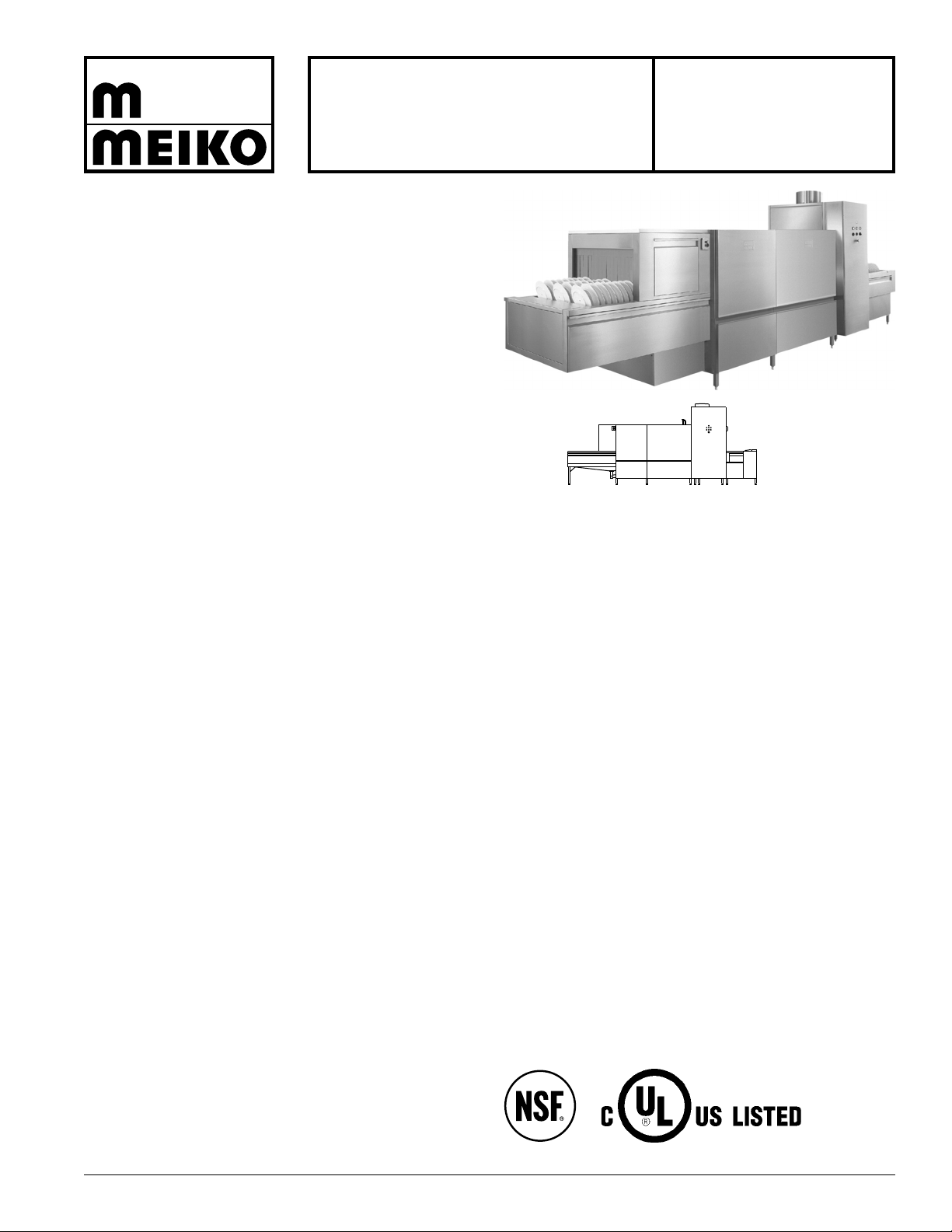
Meiko B-US 281 LPW General Manual
HOT WATER
SANITIZING
B-US 281 LPW
FLIGHT-TYPE
WAREWASHERS
Meiko's flight-type conveyors are the ideal choice for highvolume applications. They feature dramatically improved
water savings and Meiko’s exclusive Chemical Savings
System (CSS) that reduces detergent consumption from
30-50 percent.
Other standard features include computer-positioned wash
and prewash arms that are pre-assembled into easilyremoved manifolds. Nozzles are slotted and concave to
minimize clogging, and feature captivated end caps which
can’t be lost during cleaning. A double-wall, insulated, flush
stainless steel exterior is present on all sides to conserve
energy and improve the working enviroment. Meiko’s
exclusive, optional Waste Air Heat Recovery System is
available on all models. This system eliminates the need for
the final hot water rinse to be supplied by an external water
heater, and dramatically improves energy efficiency.
As with all products synonymous with the name “Meiko,” engineering excellence, manufacturing quality and performance
come to the forefront in the B-US 281 LPW flight machine.
B-US 281 LPW
Model B-US 281 LPW includes: prewash section, wash section, pumped auxiliary rinse zone, pumped fresh water final
rinse.
Standard Features:
• Low NSF-rated water consumption
• High capacity
• Large opening (21-5/8” H x 28-1/2” W) accommodates
sheet pans and other large ware
• Pumped auxiliary rinse
• Pumped fresh water final rinse
• Built-in booster heater (steam or electric)
• Standard Chemical Savings System (CSS) Basic reduces
detergent consumption by up to 30%
• Flush stainless steel exterior panels with double-wall,
insulated construction
• Central control panel with simple electro-mechanical controls
• Start/stop controls at both ends of the machine
• Two-speed conveyor - adjustable during operation to
accommodate varying levels of soil
• Stainless steel prewash and wash pump assemblies with
vertically-mounted, self-draining pumps and powerful 3 hp
motors
• V-shaped prewash and wash tanks for faster draining and
easier cleaning
• Block-manifold wash arms for fast removal and cleaning
• Tethered or “captivated” wash arm end caps
• Slotted, concave, non-clogging wash arm nozzles
• Large, balanced front access doors stay open without latching
• Contacts for external fan control, detergent and rinse aid
dispensing systems
Options:
• Waste Air Heat Recovery System - utilizes heat generated
by the machine to heat the incoming fresh water. This
utilizes “free” energy, eliminates the need for an external
boiler or water heater, and allows the machine to use an
incoming water supply with temperatures as low as 50°F
• CSS Top - additional pre-flushing system prior to the
prewash, that includes cyclone separators to actively
remove food soil from the recirculated water in the machine.
The additional pre-flushing nozzles help to reduce the need
for thorough pre-scrapping of ware by the dishroom staff.
In addition, reducing the overall soil level of the wash water
improves washing performanceand reduces detergent
consumption by up to 50%
• Steam or electric tank/booster heat
• Single blower dryer (steam or electric)
• Dual blower dryer (steam or electric)
• Low-ceiling configuration (side vent and lower-opening front
access doors)
• Split, hinged front access doors
• Load and unload ends in various lengths
• Conveyor belts in varying configurations to accommodate
special ware
B-US 281 LPW • Updated 8-09 Meiko • 1349 Heil Quaker Blvd. • La Vergne, TN 37086 • (800) 55-MEIKO • FAX (615) 399-6620 • www.meiko.us
on-off
controls
control panel
on-off
controls
H,C
CR
D
HH
S
CRCR
C
D
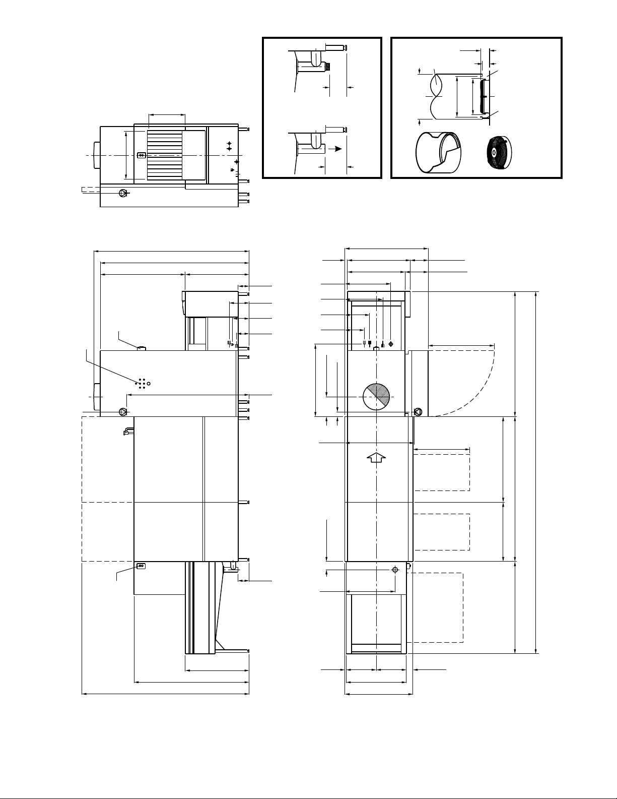
6-1/2"
[165mm]
3' 2" [965mm]
7' 4-5/8" [2250mm]
7' 8-1/2" [2350mm]
3' 5-3/8"
[1050mm]
2' 5-7/8"
[760mm]
2' 11-3/8" [900mm]
7' 2-5/8" [2200mm]
4-7/8" [125mm]
2-3/4" [70mm]
11-3/4" [300mm]
3' 7-1/4" [1100mm]
1' 2-3/4"
[375mm]
1' 10-5/8"
[575mm]
2' 3-3/8"
[695mm]
1' 1-3/4" [350mm]
1-5/8"
[40mm]
10-5/8" [270mm]
3' 1-3/8" [950mm]
4' 1-5/8" [1260mm]
4' 3-1/8" [1300mm]
4' 2-5/8" [1285mm]
6-3/4"
[170mm]
7-1/2"
[190mm]
9-7/8"
[250mm]
11-3/4"
[300mm]
2' 10-1/4" [870mm]
11-5/8"
[295mm]
6' 7/8"
[1850mm]
D
2' 4-1/2" [724mm]
horizontal
clearance
3' 2" [965mm]
5' 8-1/2" [1740mm]
8' 3-5/8" [2530mm]
1' 5-7/8"
[455mm]
3/4"
[20mm]
3-7/8"
[100mm]
1' 5-7/8"
[455mm]
3' 4-1/2" [1030mm]
2' 11-7/8" [910mm]
S
H
C
CR
1' 9-5/8" [550mm]
vertical clearance
Load section length
(L1)
Unload section length
(U1)
B-US 281 LPW, Left-to-Right
2' 9-7/8" [860mm]
recommended for
scrap screen removal
Vent shroud
(supplied
by customer)
Machine
exhaust vent
Ø 20" or 500mm
Ø 18” or 450mm
Ø 16" or
400mm
Gap permits
room air to
enter vent
shroud
Condensation
can be drained
into machine
(drain supplied
by customer)
Vent shroud
(supplied by
customer)
3-1/8"
(80mm)
3-7/8"
(100mm)
Detail View: Vent
3' 3-3/8" [1000mm]
recommended for
service access
Detail View: Drain
D
D
6-3/4"
[170mm]
Directly
above floor
drain
2" NPT
adapter
(supplied)
or
5-1/2"
[140mm]
Standard machines:
Machines with blower dryer:
All machines:
824 CFM
1059 CFM
+120 CFM room air
SS
Overall machine length = Load section length (L1) + Unload section length (U1) + Wash section length (7' 2-5/8"/2200mm)
Choose a load and unload section from the choices below.
Plan View
Front Elevation
Right Side Elevation
Approx. flow rate 57 gpm (216 liters/min).
B-US 281 LPW • Updated 2-07 Page 2
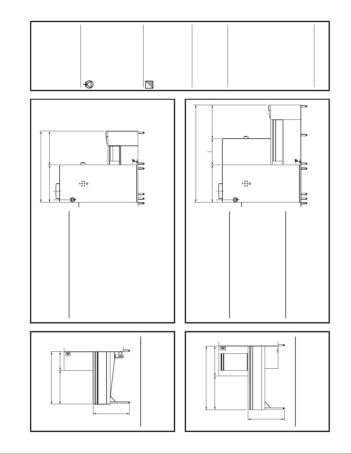
Load section length (L1) Clear load area (L2)
3' 7-1/4" (1100mm) 1' 11-5/8" (600mm)
4' 7-1/8" (1400mm) 2' 11-3/8" (900mm)
7' 10-1/2" (2400mm) 6' 2-3/4" (1900mm)
*7' 10-1/2" (2400mm) 6' 2-3/4" (1900mm)
* With optional 2' 6-3/8" (770mm) loading height
*
D
1' 7-5/8"
[500mm]
Load section length
(L1)
Clear load length
(L2)
Load Sections - CSS Basic
3' 2" [965mm]
Load section length (L1) Clear load area (L2)
4' 7-1/8" (1400mm) 1' 11-5/8" (600mm)
5' 6-7/8" (1700mm) 2' 11-3/8" (900mm)
*8' 10-3/8" (2700mm) 6' 2-3/4" (1900mm)
* With optional 2' 6-3/8" (770mm) loading height
*
Load Sections - CSS Top
D
2' 7-1/2" [800mm]
Load section length
(L1)
Clear load length
(L2)
3' 2" [965mm]
H,C
SS
CR
Unload section length (U1) Clear unload area (U2)
6' 2-3/4" (1900mm) 2' 11-3/8" (900mm)
8' 6-3/8" (2600mm) 5' 3" (1600mm)
9' 10-1/8" (3000mm) 6' 6-3/4" (2000mm)
10' 9-7/8" (3300mm) 7' 6-1/2" (2300mm)
11' 9-3/4" (3600mm) 8' 6-3/8" (2600mm)
13' 1-1/2" (4000mm) 9' 10-1/8" (3000mm)
16' 7/8" (4900mm) 12' 9-1/2" (3900mm)
Unload Sections - Standard
(no blower dryer)
3'3-3/8"[1000mm]
Unload section length
(U1)
Clear unload length
(U2)
Single blower dryer
Unload section length (U1) Clear unload area (U2)
8' 6-3/8" (2600mm) 2' 11-3/8" (900mm)
9' 10-1/8" (3000mm) 4' 3-1/8" (1300mm)
10' 9-7/8" (3300mm) 5' 3" (1600mm)
11' 9-3/4" (3600mm) 6' 2-3/4" (1900mm)
13' 1-1/2" (4000mm) 7' 6-1/2" (2300mm)
16-7/8" (4900mm) 10' 6" (3200mm)
Unload Sections -
with Blower Dryer
3' 3-3/8" [1000mm]
Unload section length
(U1)
Single blower dryer: 2' 3-1/2" [700mm]
Dual blower dryer: 5' 5" [1650mm]
Dual blower dryer
Unload section length (U1) Clear unload area (U2)
10' 9-7/8" (3300mm) 2' 1-5/8" (650mm)
11' 9-3/4" (3600mm) 3' 1-3/8" (950mm)
13' 1-1/2" (4000mm) 4' 5-1/8" (1350mm)
16-7/8" (4900mm) 7' 4-5/8" (2250mm)
H,C
SS
CR
Clear unload length
(U2)
D
Electrical connection
Machines with electric heat:
Machines with steam heat:
4 (four)
terminal blocks centered at location
shown.
1 (one)
terminal block at location shown.
Each terminal block is 4-wire with
ground (no neutral).
Opening(s) in the machine for the
supply lines are NOT provided and
should be executed on-site using
appropriate strain relief device(s).
Individual
disconnect with lockout/tagout strongly
recommended for each supply
(provided by customer).
Vent connection
Indirect connection to machine required
to avoid negative pressure inside
dishwasher. See
The connection must be corrosion-
resistant and frost-free. In particular,
provision must be made to prevent air
temperatures of 32°F/0°C or colder
from reaching the machine at any time.
A provision for draining moisture from
the waste air pipe is STRONGLY
RECOMMENDED.
Detail View: Vent.
Warm water connection
Used only for initial fill
Used for both initial fill and final rinse
on units with
Waste Air Heat Recovery System.
(single water connection) on all other
machines.
3/4" NPT, 110-140°F (43-60°C), 15-25
PSI
Cold water connection
Used only for final rinse on units
equipped with Waste Air Heat Recovery
System. Not present on other units.
1/2" NPT, 50°F (10°C), 15-25 PSI
C
H
Utilities
Steam connection
2" NPT, 15-30 PSI (1-2 bars).
For steam pressures below 15 PSI (1
bar), contact the factory. For pressures
above 30 PSI (2 bars), a regulator is
required (supplied by customer).
CONSTANT steam pressure is
REQUIRED. If supply pressure is
variable, use of a regulator is
REQUIRED (supplied by customer).
S
Condensate return connection
1-1/4" NPT. Condensate return line
MUST be pressure-free.
CR
Steam Utilities
(if so equipped)
Drain
2-15/16” (75mm) OD vertical, gravity-
fed drain outlet (HDPE piping). Optional
2" NPT male adapter supplied.
4” floor drain recommended. Additional
piping to drain (if so required) to be
supplied by customer.
Approx. flow rate 57 gpm (217 liters/min).
B-US 281 LPW • Updated 2-07 Page 3
 Loading...