

Meiko B-US232 User Manual
B-US 231/232/233
SERIES
HOT WATER
SANITIZING
FLIGHT-TYPE
WAREWASHERS
Meiko's flight-type conveyors are the ideal choice for high-volume applications. They feature dramatically improved water savings
and Meiko’s exclusive Chemical Savings System (CSS) that reduces detergent consumption from 30-50 percent. As with all products
synonymous with the name “Meiko,” engineering excellence, manufacturing quality and performance come to the forefront in the
B-US 23 Series flight machines.
• Model B-US 231 includes: wash section, pumped auxiliary rinse zone, pumped fresh water final rinse.
• Model B-US 231 PW includes: prewash section, wash section, pumped auxiliary rinse zone, pumped fresh water final rinse.
• Model B-US 231 LPW includes: large prewash section, wash section, pumped auxiliary rinse zone, pumped fresh water final rinse.
• Model B-US 232 LPW includes: large prewash section, wash section, recirculating rinse section, pumped auxiliary rinse zone,
pumped fresh water final rinse.
• Model B-US 233 LPW includes: large prewash section, two wash sections, recirculating rinse section, pumped auxiliary rinse
zone, pumped fresh water final rinse.
Exclusive Features:
• Optional Waste Air Heat Recovery System utilizes heat
generated by the machine to heat the incoming fresh water.
This utilizes “free” energy and allows the machine to use an
incoming water supply with temperatures as low as 50°F.
• Insulated double-wall construction on doors, front, top
and back
• Pumped auxiliary rinse supplements the pumped fresh
water final rinse
• Standard Chemical Savings System (CSS) Basic reduces
detergent consumption by 30% (based on Meiko’s low water
consumption)
• Optional CSS Top reduces detergent consumption by 50%
Options:
• Waste Air Heat Recovery System
• Single blower dryer (steam or electric)
• Dual blower dryer (steam or electric)
• CSS Top
• Load and unload ends in various lengths
• Steam or electric tank/booster heat
• Factory-installed external fan controller
B-US 23 Series • Updated 11-04 Meiko • 917 Airpark Center Drive • Nashville, TN 37217 • (800) 55-MEIKO • FAX (615) 399-6620 • www.meiko.us
Standard Features:
• Low NSF-rated water consumption
• High capacity
• Built-in booster heater (steam or electric)
• Central control panel with simple electro-mechanical controls
• Operator-activated start/stop controls at both ends of machine
• Two-speed conveyor
• Stainless steel wash pump assemblies with verticallymounted, self-draining pumps and powerful 3 hp motors
• V-shaped wash tanks for faster draining and easier cleaning
• Block-manifold wash arms for fast removal and easier cleaning
• Tethered or “captivated” wash arm end caps
• Slotted, concave, non-clogging wash arm nozzles
• Large, balanced front access doors stay open without latching
• Contacts for external fan control and external transport control
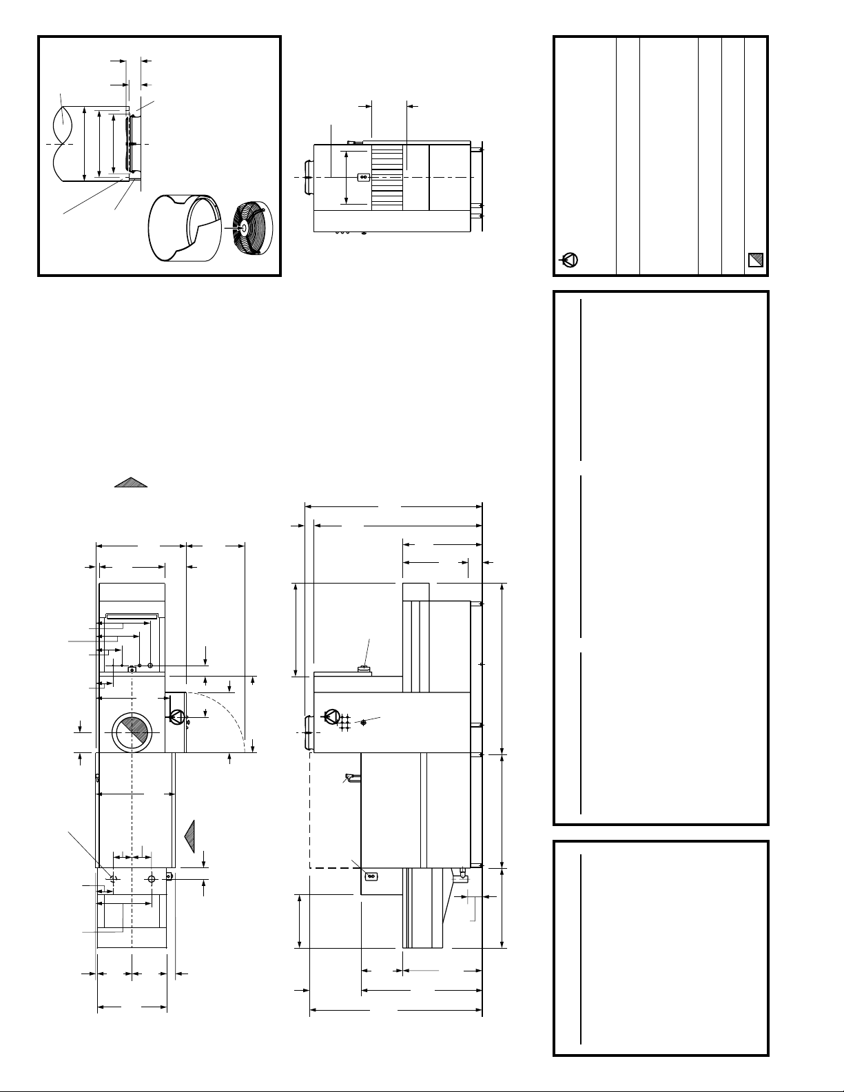
2' 2-3/4" (680mm)
3' 7-1/4" (1100mm)
2' 3-1/2"
(700mm)
Vent shroud
Left-to-Right machine shown.
Right-to-Left
machine is a
mirror
image.
All
dimensions from floor are
+/-
1/2" due to adjustable feet.
(supplied by
customer)
Condensation
trough
3-7/8"
(100mm)
3-1/8"
(80mm)
1' 7-5/8" (500mm) dia.
1' 5-3/4" (450mm) dia.
Condensation
can be drained
into machine
1' 3-3/4"
(400mm) dia.
(drain supplied
by customer)
Gap permits
room air to
SUPPLIED BY
CUSTOMER:
enter vent
Vent shroud to be
shroud
constructed with 1"
(25mm) trough to
VENT
collect condensation,
which can be
drained into machine
DETAIL
SUPPLIED WITH
MACHINE:
VIEW
Exhaust vent
1' 11-3/8"
Left-to-Right machine shown.
(600mm)
Right-to-Left machine is a
horizontal
clearance
mirror image.
All dimensions from floor are
+/- 1/2" due to adjustable feet.
passing height
1' 3-3/4" (400mm)
Electrical connection
Units with steam heat: Single terminal block at the location shown.
UTILITY CONNECTIONS
ELEVATION VIEW (RIGHT)
DUAL BLOWER DRYER
Unl (U1) Clear unload (U2)oad section
Units with electric heat: 4 (four) individual terminal blocks, approx.
2-1/2" (64mm) apart, centered on the location shown.
6' 7/8" (1850mm)-long drying tunnel:
Leads must be appropriate for electrical supply. Maximum wire
gauge #2 AWG.All connection points to be drilled during installation.
9' 10-1/8" (3000mm) 3' 9-1/4" (1150mm)
10' 9-7/8" (3300mm) † 4' 11" (1500mm) †
13' 1-1/2" (4000mm) 6' 2-3/4" (1900mm)
Drain
3" (76mm) IPS drain. 4" indirect floor drain recommended.
Water connection(s)
D
7' 6-1/2" (2300mm)-long drying tunnel:
16' 7/8" (4900mm) 12' 5-5/8" (3800mm)
10' 9-7/8" (3300mm) † 3' 3-3/8" (1000mm) †
Used only for initial fill
3/4" NPT. on units that equipped with
optional waste air heat recovery system. Used as single water
connection on all other units.
H
8' 10-3/8" (2700mm)-long drying tunnel:
13' 1-1/2" (4000mm) 5' 6-7/8" (1700mm)
16' 7/8" (4900mm) 8' 6-3/8" (2600mm)
Used only for final rinse
1/2" NPT. on units equipped with optional
waste air heat recovery system. Not present on other units.
C
13' 1-1/2" (4000mm) † 4' 3-1/8" (1300mm) †
16' 7/8" (4900mm) 7' 2-5/8" (2200mm)
Steam connection
Units with steam tank/booster heat only. 1-1/2" NPT.SCondensate return connection
10' 2" (3100mm)-long drying tunnel:
13' 1-1/2" (4000mm) † 2' 11-3/8" (900mm) †
16' 7/8" (4900mm) 5' 10-7/8" (1800mm)
Units with steam tank/booster heat only. 1" NPT.CRVent connection
See exhaust vent detail view.
1' 6-7/8"
(480mm)
for indirect floor drain
Recommended location
1-5/8"
1' 11-1/4"
11-7/8"
8-5/8"
8-7/8"
7-7/8"
2' 3/4"
(40mm)
(590mm)
(300mm)
(220mm)
(225mm)
(200mm)
(630mm)
C
2' 5-1/8"
H
8-1/4"
Direction
belt travel
of conveyor
(740mm)
CR
8-5/8"
(210mm)
3' 4-1/8"
(1020mm)
S
2' 9-1/8"
(840mm)
2' 11-3/8"
(220mm)
D
9-1/2"
(900mm)
(240mm)
PLAN
2' 2-3/4"
3-7/8"
(100mm)
2' 3-1/2"
(700mm)
VIEW
Front
4-7/8"
(125mm)
(680mm)
2' 2-3/4" (680mm)
3' 7-1/4" (1100mm)
3-7/8"
(100mm)
U2
clear unload area
(FRONT)
ELEVATION VIEW
L2
clear load area
breaker
Fill vacuum
Start/stop
6' 2-3/4"
(1900mm)
controls
6' 6-3/4"
controls
Start/stop
Control
(2000mm)
panel
2' 11-3/8"
(900mm)
2' 6-1/8"
Aux. rinse
pump 0.75 hp
(765mm)
Final rinse
pump 0.75 hp
3.0 hp
Wash pump
6-1/2"
(165mm)
5-3/8"
(135mm)
U1
unload section length
4' 3-1/8" (1300mm)
L1
load section length
SINGLE BLOWER DRYER
Unl (U1) Clear unload (U2)oad section
3' 7-1/4" (1100mm)-long drying tunnel:
6' 2-3/4" (1900mm) 2' 7-1/2" (800mm)
7' 6-1/2" (2300mm) † 3' 11-1/4" (1200mm) †
Unl (U1) Clear unload (U2)oad section
6' 2-3/4" (1900mm) † 3' 5-3/8" (1050mm) †
8' 6-3/8" (2600mm) 4' 11" (1500mm)
7' 6-1/2" (2300mm) 4' 9-1/8" (1450mm)
8' 6-3/8" (2600mm) 5' 8-7/8" (1750mm)
9' 10-1/8" (3000mm) 7' 5/8" (2150mm)
UNLOAD SECTIONS
STANDARD
9' 10-1/8" (3000mm) 6' 2-3/4" (1900mm)
10' 9-7/8" (3300mm) 7' 2-5/8" (2200mm)
13' 1-1/2" (4000mm) 9' 6-1/8" (2900mm)
16' 7/8" (4900mm) 12' 5-5/8" (3800mm)
10' 9-7/8" (3300mm) 8' 1/2" (2450mm)
13' 1-1/2" (4000mm) 10' 4" (3150mm)
16' 7/8" (4900mm) 14' 9-1/8" (4500mm)
4' 11" (1500mm)-long drying tunnel:
7' 6-1/2" (2300mm) 2' 7-1/2" (800mm)
8' 6-3/8" (2600mm) † 3' 7-1/4" (1100mm) †
9' 10-1/8" (3000mm) 4' 11" (1500mm)
10' 9-7/8" (3300mm) 5' 10-7/8" (1800mm)
13' 1-1/2" (4000mm) 8' 2-1/2" (2500mm)
16' 7/8" (4900mm) 11' 1-7/8" (3400mm)
6' 2-3/4" (1900mm)-long drying tunnel:
9' 10-1/8" (3000mm) † 3' 7-1/4" (1100mm) †
10' 9-7/8" (3300mm) 4' 7-1/8" (1400mm)
13' 1-1/2" (4000mm) 6' 10-5/8" (2100mm)
16' 7/8" (4900mm) 9' 10-1/8" (3000mm)
Consult Meiko for special ware
considerations.
† Recommended standard element.
3/4"
(20mm)
B-US 231
1' 3-3/8"
(390mm)
2' 6-3/4"
1' 3-3/8"
(780mm)
(390mm)
3-7/8"
(100mm)
(562mm)
1' 10-1/8"
door
opening
2' 6-1/2"
6' 4-3/4"
(775mm)
(1950mm)
4' 6-5/8"
(1388mm)
2' 11-3/8"
(900mm)
LOAD SECTIONS
STANDARD
Load section length (L1) Clear load area (L2)
2' 11-3/8" (900mm) † 1' 11-5/8" (600mm) †
3' 7-1/4" (1100mm) 2' 7-1/2" (800mm)
4' 7-1/8" (1400mm) 3' 7-1/4" (1100mm)
7' 10-1/2" (2400mm) 6' 10-5/8" (2100mm)
7' 10-1/2" (2400mm)* 6' 10-5/8" (2100mm)*
Meiko for special ware considerations.
* With optional 2' 6-3/8" (770mm) loading height
† Recommended standard element. Consult

B-US 231 Technical Specifications
Operating Capacities (NSF Rated)
Dishes per hour (maximum) ...........................................7,920
Consumption ..................................... 100 U.S. gals. (379
Conveyor Specifications
Conveyor belt speed:
Minimum ........................................................ 4’ (1.2m)/min.
Maximum ....................................................... 6’ (1.8m)/min.
Horizontal clearance ................................. 1’ 11-3/8” (600mm)
Vertical clearance .......................................1’ 3-3/4” (400mm)
Conveyor belt minimum peg spacing .............. 2-1/8” (55mm)
Water Specifications
Minimum water temperatures:
Wash tank....................................................... 160°F (72°C)
Auxiliary rinse ................................................. 165°F (77°C)
Final rinse ....................................................... 180°F (82°C)
Water requirements:
Recommended fill temp ..................... 110-140°F (43-60°C)
Minimum incoming water temperature:
For 40°F/22°C minimum rise ...................... 140°F (60°C)
For 70°F/39°C minimum rise ...................... 110°F (43°C)
For 130°F/72°C minimum rise * ................... 50°F (10°C)
* Requires waste air heat recovery option.
Initial fill ................................................. 45 U.S. gals. (250l)
Consumption at 100% cap. ........... 100 U.S. gals. (379
l)/hr.
l)/hr.
Venting Specifications
Venting requirements (standard) ................ 471 CFM (800m3/h)
Venting requirements (with blower dryer) . 706 CFM (1200m
Room air to cool exhaust (recommended) ...... 120 CFM (202m
Waste air temp. (approx.) .................................. 122°F (50°C)
Waste air temp. (with optional waste
air heat recovery option, approx.) ....................... 95°F (35°C)
Minimum incoming water line size:
Initial fill line (units with waste heat
recovery option) or single water
connection (all other units) ....................................... 3/4” NPT
Final rinse line (units with waste heat
recovery option only) ................................................ 1/2” NPT
Minimum final rinse flow rate .................... 1.8 U.S. gals.(6.8l)/min.
Recommended max. water hardness ............ 4 grains/U.S. gal.
Drain ................................................ 3” IPS drain pipe; indirect
connection to 4” (102mm)
floor drain recommended
Tank capacities:
Wash tank ................................................ 31 U.S. gals. (117l)
Auxiliary rinse tank ..................................... 16 U.S. gals. (60
3
/h)
3
/h)
l)
Machine Electrical Specifications
Total Machine Current Draw: 208 V/60 Hz/3 Ph 230 V/60 Hz/3 Ph 460 V/60 Hz/3 Ph
Electric tank heat, 40°F/22°C rise booster 149.0 A 134.6 A 66.1 A
Electric tank heat, 70°F/39°C rise booster 174.0 A 157.1 A 77.1 A
Electric tank heat, opt. waste air heat recovery (130°F/72°C rise) 174.0 A 157.1 A 77.1 A
Steam tank heat/steam booster 15.0 A 14.6 A 7.1 A
Single blower dryer (electric) Add 26.5 A Add 23.3 A Add 12.3 A
Single blower dryer (steam) Add 1.6 A Add 1.4 A Add 0.9 A
Dual blower dryer (electric) Add 28.0 A Add 24.6 A Add 13.1 A
Dual blower dryer (steam) Add 3.1 A Add 2.7 A Add 1.7 A
Component Electrical Specifications
Motors:
Wash pump motor ........................... 3 hp
Auxiliary rinse pump motor......... 0.75 hp
Final rinse pump motor .............. 0.75 hp
Conveyor motor / min spd ......... 0.17 hp
Conveyor motor / max speed ..... 0.25 hp
Vent motor .................................. 0.21 hp
Steam Specifications (steam-heated units only)
Steam line connection ........................................... 1-1/2” NPT
Condensate return connection .................................... 1” NPT
Recommended steam pressure ..............15-30 psi (1-2 bars)
Blower dryer motors (1x for single blower
dryer, 2x for dual blower dryers):
• Electric or steam heat,
208 V or 240 V .......................... 0.5 hp
• Electric or steam heat,
460 V ......................................... 0.6 hp
Consumption
Incoming water temp. 110°F/43°C........... 216 lbs./hr. (57 kW)
Incoming water temp. 140°F/60°C ..........182 lbs./hr. (48 kW)
Incoming water temp. 50°F/10°C (with
optional waste air heat recovery sys.) ..... 216 lbs./hr. (57 kW)
Optional steam blower dryer ................ Add 34 lbs./hr. (9 kW)
Electric Heating Elements (electricallyheated units only):
Wash tank.................................... 27 kW
Auxiliary rinse tank ......................... 9 kW
Booster heater / 40°F rise ........... 12 kW
Booster heater / 70°F rise ........... 21 kW
Booster heater / Waste heat
recovery option, 130°F rise ......... 21 kW
Blower dryer heater (single
or dual blower dryers ) ............. 1 x 9 kW
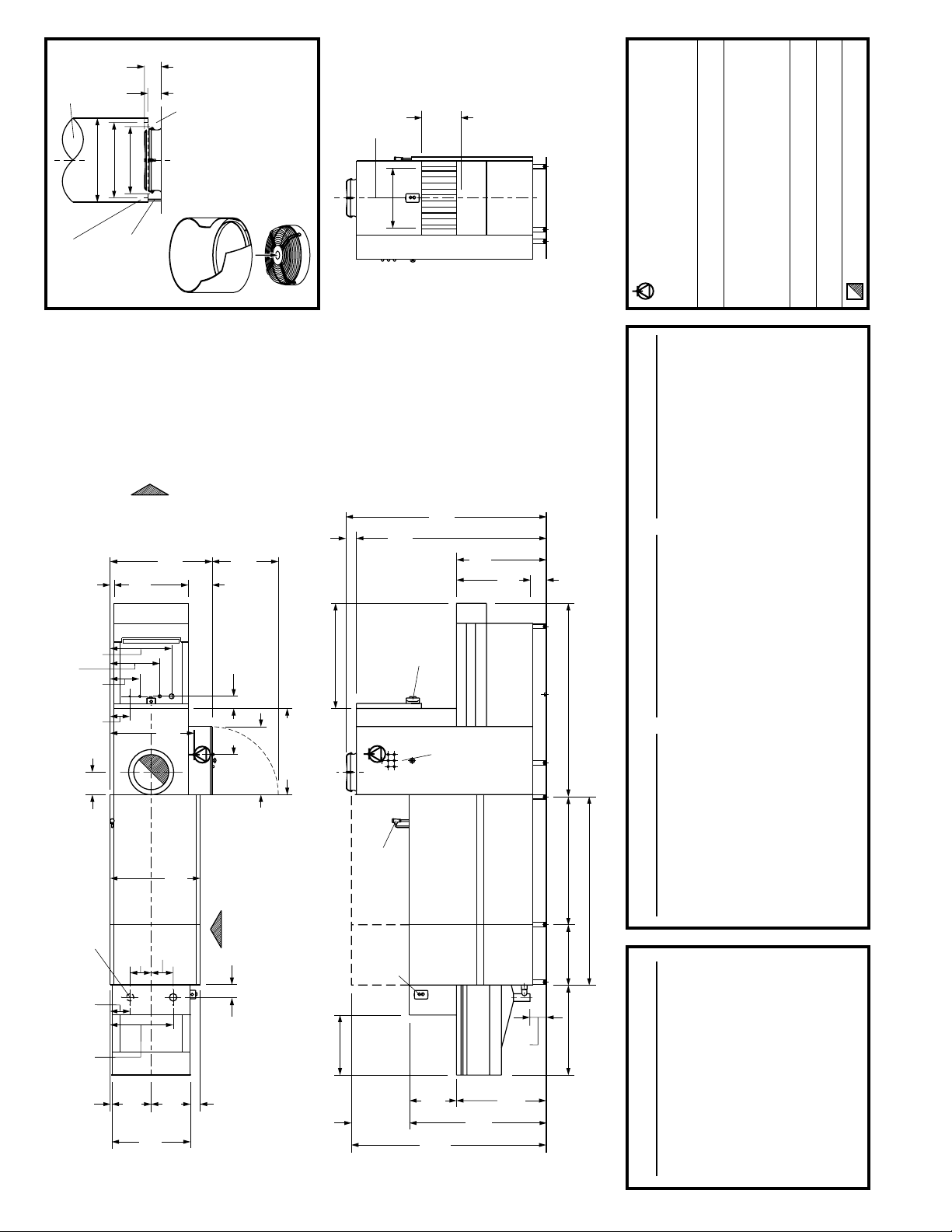
2' 2-3/4" (680mm)
3' 7-1/4" (1100mm)
2' 3-1/2"
(700mm)
Vent shroud
Left-to-Right machine shown.
Right-to-Left
machine is a
mirror
image.
All
dimensions from floor are
+/-
1/2" due to adjustable feet.
(supplied by
customer)
Condensation
trough
1-5/8"
3-7/8"
3-1/8"
1' 7-5/8" (500mm) dia.
1' 5-3/4" (450mm) dia.
Condensation
can be drained
into machine
(40mm)
(100mm)
(80mm)
1' 3-3/4"
(400mm) dia.
(drain supplied
by customer)
2' 5-1/8"
Direction
belt travel
of conveyor
(740mm)
3' 4-1/8"
(1020mm)
Gap permits
room air to
SUPPLIED BY
CUSTOMER:
9-1/2"
enter vent
shroud
Vent shroud to be
constructed with 1"
(240mm)
(25mm) trough to
collect condensation,
which can be
2' 2-3/4"
VENT
DETAIL
drained into machine
SUPPLIED WITH
(680mm)
VIEW
MACHINE:
Exhaust vent
3-7/8"
1' 11-3/8"
Left-to-Right machine shown.
(100mm)
(600mm)
horizontal
Right-to-Left machine is a
mirror image.
clearance
All dimensions from floor are
6' 2-3/4"
(1900mm)
+/- 1/2" due to adjustable feet.
passing height
1' 3-3/4" (400mm)
6' 6-3/4"
(2000mm)
2' 11-3/8"
(900mm)
2' 6-1/8"
(765mm)
ELEVATION VIEW (RIGHT)
5-3/8"
(135mm)
Used only for initial fill
Drain
3" (76mm) IPS drain. 4" indirect floor drain recommended.
Water connection(s)
Electrical connection
Units with steam heat: Single terminal block at the location shown.
Units with electric heat: 4 (four) individual terminal blocks, approx.
2-1/2" (64mm) apart, centered on the location shown.
Leads must be appropriate for electrical supply. Maximum wire
UTILITY CONNECTIONS
gauge #2 AWG.All connection points to be drilled during installation.
3/4" NPT. on units that equipped with
D
DUAL BLOWER DRYER
Unl (U1) Clear unload (U2)oad section
6' 7/8" (1850mm)-long drying tunnel:
9' 10-1/8" (3000mm) † 3' 9-1/4" (1150mm) †
10' 9-7/8" (3300mm) 4' 11" (1500mm)
7' 6-1/2" (2300mm)-long drying tunnel:
13' 1-1/2" (4000mm) 6' 2-3/4" (1900mm)
16' 7/8" (4900mm) 12' 5-5/8" (3800mm)
10' 9-7/8" (3300mm) † 3' 3-3/8" (1000mm) †
13' 1-1/2" (4000mm) 5' 6-7/8" (1700mm)
Used only for final rinse
optional waste air heat recovery system. Used as single water
connection on all other units.
1/2" NPT. on units equipped with optional
H
8' 10-3/8" (2700mm)-long drying tunnel:
16' 7/8" (4900mm) 8' 6-3/8" (2600mm)
waste air heat recovery system. Not present on other units.
C
13' 1-1/2" (4000mm) † 4' 3-1/8" (1300mm) †
16' 7/8" (4900mm) 7' 2-5/8" (2200mm)
Steam connection
Units with steam tank/booster heat only. 1-1/2" NPT.SCondensate return connection
10' 2" (3100mm)-long drying tunnel:
13' 1-1/2" (4000mm) † 2' 11-3/8" (900mm) †
16' 7/8" (4900mm) 5' 10-7/8" (1800mm)
Units with steam tank/booster heat only. 1" NPT.CRVent connection
See exhaust vent detail view.
1' 6-7/8"
1' 11-1/4"
(480mm)
11-7/8"
8-5/8"
8-7/8"
for indirect floor drain
Recommended location
7-7/8"
(200mm)
2' 3/4"
(630mm)
(590mm)
(300mm)
(220mm)
(225mm)
C
H
8-1/4"
CR
8-5/8"
(210mm)
S
2' 9-1/8"
(840mm)
2' 11-3/8"
(220mm)
D
(900mm)
3-7/8"
(100mm)
2' 3-1/2"
(700mm)
VIEW
PLAN
Front
4-7/8"
(125mm)
2' 2-3/4" (680mm)
3' 7-1/4" (1100mm)
U2
clear unload area
(FRONT)
ELEVATION VIEW
L2
clear load area
breaker
Fill vacuum
Start/stop
controls
controls
Start/stop
Control
panel
Aux. rinse
U1
unload section length
Final rinse
pump 0.75 hp
pump 0.75 hp
4' 3-1/8" (1300mm)
3.0 hp
Wash pump
1.0 hp
Prewash pump
1' 11-5/8"
6' 2-3/4" (1900mm)
(600mm)
SINGLE BLOWER DRYER
Unl (U1) Clear unload (U2)oad section
3' 7-1/4" (1100mm)-long drying tunnel:
7' 6-1/2" (2300mm) 3' 11-1/4" (1200mm)
8' 6-3/8" (2600mm) † 4' 11" (1500mm) †
6' 2-3/4" (1900mm) 3' 5-3/8" (1050mm)
7' 6-1/2" (2300mm) † 4' 9-1/8" (1450mm) †
8' 6-3/8" (2600mm) 5' 8-7/8" (1750mm)
9' 10-1/8" (3000mm) 6' 2-3/4" (1900mm)
9' 10-1/8" (3000mm) 7' 5/8" (2150mm)
UNLOAD SECTIONS
STANDARD
Unl (U1) Clear unload (U2)oad section
10' 9-7/8" (3300mm) 7' 2-5/8" (2200mm)
13' 1-1/2" (4000mm) 9' 6-1/8" (2900mm)
16' 7/8" (4900mm) 12' 5-5/8" (3800mm)
10' 9-7/8" (3300mm) 8' 1/2" (2450mm)
13' 1-1/2" (4000mm) 10' 4" (3150mm)
16' 7/8" (4900mm) 14' 9-1/8" (4500mm)
4' 11" (1500mm)-long drying tunnel:
7' 6-1/2" (2300mm) 2' 7-1/2" (800mm)
8' 6-3/8" (2600mm) † 3' 7-1/4" (1100mm) †
9' 10-1/8" (3000mm) 4' 11" (1500mm)
10' 9-7/8" (3300mm) 5' 10-7/8" (1800mm)
13' 1-1/2" (4000mm) 8' 2-1/2" (2500mm)
16' 7/8" (4900mm) 11' 1-7/8" (3400mm)
6' 2-3/4" (1900mm)-long drying tunnel:
9' 10-1/8" (3000mm) † 3' 7-1/4" (1100mm) †
10' 9-7/8" (3300mm) 4' 7-1/8" (1400mm)
13' 1-1/2" (4000mm) 6' 10-5/8" (2100mm)
16' 7/8" (4900mm) 9' 10-1/8" (3000mm)
Consult Meiko for special ware
considerations.
† Recommended standard element.
L1
6-1/2"
(165mm)
load section length
3/4"
(20mm)
B-US 231 PW
1' 3-3/8"
(390mm)
2' 6-3/4"
1' 3-3/8"
(780mm)
(390mm)
3-7/8"
(100mm)
(562mm)
1' 10-1/8"
door
opening
2' 6-1/2"
6' 4-3/4"
(775mm)
(1950mm)
4' 6-5/8"
(1388mm)
2' 11-3/8"
(900mm)
LOAD SECTIONS
STANDARD CSS BASIC
Load section length (L1) Clear load area (L2)
2' 11-3/8" (900mm) † 1' 11-5/8" (600mm) †
3' 7-1/4" (1100mm) 2' 7-1/2" (800mm)
4' 7-1/8" (1400mm) 3' 7-1/4" (1100mm)
7' 10-1/2" (2400mm) 6' 10-5/8" (2100mm)
7' 10-1/2" (2400mm)* 6' 10-5/8" (2100mm)*
Meiko for special ware considerations.
* With optional 2' 6-3/8" (770mm) loading height
† Recommended standard element. Consult

B-US 231 PW Technical Specifications
Operating Capacities (NSF Rated)
Dishes per hour (maximum) ...........................................7,920
Consumption ..................................... 100 U.S. gals. (379
Conveyor Specifications
Conveyor belt speed:
Minimum ........................................................ 4’ (1.2m)/min.
Maximum ....................................................... 6’ (1.8m)/min.
Horizontal clearance ................................. 1’ 11-3/8” (600mm)
Vertical clearance .......................................1’ 3-3/4” (400mm)
Conveyor belt minimum peg spacing .............. 2-1/8” (55mm)
Water Specifications
Minimum water temperatures:
Prewash tank .................................................. 110°F (43°C)
Wash tank....................................................... 160°F (72°C)
Auxiliary rinse ................................................. 165°F (77°C)
Final rinse ....................................................... 180°F (82°C)
Water requirements:
Recommended fill temp ..................... 110-140°F (43-60°C)
Minimum incoming water temperature:
For 40°F/22°C minimum rise ...................... 140°F (60°C)
For 70°F/39°C minimum rise ...................... 110°F (43°C)
For 130°F/72°C minimum rise * ................... 50°F (10°C)
* Requires waste air heat recovery option.
Initial fill ................................................. 66 U.S. gals. (250l)
Consumption at 100% cap. ........... 100 U.S. gals. (379
l)/hr.
l)/hr.
Venting Specifications
Venting requirements (standard) ................ 471 CFM (800m3/h)
Venting requirements (with blower dryer) . 706 CFM (1200m
Room air to cool exhaust (recommended) ...... 120 CFM (202m
Waste air temp. (approx.) .................................. 122°F (50°C)
Waste air temp. (with optional waste
air heat recovery option, approx.) ....................... 95°F (35°C)
Minimum incoming water line size:
Initial fill line (units with waste heat
recovery option) or single water
connection (all other units) ....................................... 3/4” NPT
Final rinse line (units with waste heat
recovery option only) ................................................ 1/2” NPT
Minimum final rinse flow rate .................... 1.8 U.S. gals.(6.8l)/min.
Recommended max. water hardness ............ 4 grains/U.S. gal.
Drain ................................................ 3” IPS drain pipe; indirect
connection to 4” (102mm)
floor drain recommended
Tank capacities:
Prewash tank ............................................. 19 U.S. gals. (72l)
Wash tank ................................................ 31 U.S. gals. (117l)
Auxiliary rinse tank ..................................... 16 U.S. gals. (60
3
/h)
3
/h)
l)
Machine Electrical Specifications
Total Machine Current Draw: 208 V/60 Hz/3 Ph 230 V/60 Hz/3 Ph 460 V/60 Hz/3 Ph
Electric tank heat, 40°F/22°C rise booster 151.8 A 137.5 A 67.5 A
Electric tank heat, 70°F/39°C rise booster 176.8 A 160.0 A 78.5 A
Electric tank heat, opt. waste air heat recovery (130°F/72°C rise) 176.8 A 160.0 A 78.5 A
Steam tank heat/steam booster 17.8 A 17.5 A 8.5 A
Single blower dryer (electric) Add 26.5 A Add 23.3 A Add 12.3 A
Single blower dryer (steam) Add 1.6 A Add 1.4 A Add 0.9 A
Dual blower dryer (electric) Add 28.0 A Add 24.6 A Add 13.1 A
Dual blower dryer (steam) Add 3.1 A Add 2.7 A Add 1.7 A
Component Electrical Specifications
Motors:
Prewash pump motor ................. 0.75 hp
Wash pump motor ........................... 3 hp
Auxiliary rinse pump motor......... 0.75 hp
Final rinse pump motor .............. 0.75 hp
Conveyor motor / min spd ......... 0.17 hp
Conveyor motor / max speed ..... 0.25 hp
Vent motor .................................. 0.21 hp
Steam Specifications (steam-heated units only)
Steam line connection ........................................... 1-1/2” NPT
Condensate return connection .................................... 1” NPT
Recommended steam pressure ..............15-30 psi (1-2 bars)
Blower dryer motors (1x for single blower
dryer, 2x for dual blower dryers):
• Electric or steam heat,
208 V or 240 V .......................... 0.5 hp
• Electric or steam heat,
460 V ......................................... 0.6 hp
Consumption
Incoming water temp. 110°F/43°C........... 216 lbs./hr. (57 kW)
Incoming water temp. 140°F/60°C ..........182 lbs./hr. (48 kW)
Incoming water temp. 50°F/10°C (with
optional waste air heat recovery sys.) ..... 216 lbs./hr. (57 kW)
Optional steam blower dryer ................ Add 34 lbs./hr. (9 kW)
Electric Heating Elements (electricallyheated units only):
Wash tank.................................... 27 kW
Auxiliary rinse tank ......................... 9 kW
Booster heater / 40°F rise ........... 12 kW
Booster heater / 70°F rise ........... 21 kW
Booster heater / Waste heat
recovery option, 130°F rise ......... 21 kW
Blower dryer heater (single
or dual blower dryers ) ............. 1 x 9 kW
 Loading...