

Meiko AZP80 Installation Manual
MODEL AZP 80
Waste Pulper (USA Version)
OWNER’S INSTALLATION, OPERATION AND
MAINTENANCE MANUAL
Meiko • 917 Airpark Center Drive • Nashville, TN 37217 • Phone: (615) 399-6600 • (800) 55-MEIKO • Fax: (615) 399-6620
Rev. 05/06
TABLE OF CONTENTS
1. INTRODUCTION ................................. 3
1.1 Overview of Equipment ............................. 3
1.2 General Safety Information ........................ 4
2. TRANSPORT AND SHIPPING ............. 4
3. INSTALLATION .................................... 4
3.1 Overview of Installation ............................. 4
3.2 Requirements Before Installation .............. 5
3.3 Uncrating, Positioning and Leveling ............. 5
3.4 Connecting a Feeding Trough ................... 6
3.5 Accessing the Utility Connections ............. 7
3.6 Main Electrical Supply Connection ............ 8
3.7 Remote Control Box Installation ................ 8
3.8 Water Supply Connections ........................ 9
3.9 Drain Connection ..................................... 10
3.10 Installing a Deodorizing System .............. 11
3.11 Final Assembly ........................................ 11
4. OPERATION ....................................... 12
4.1 Location and Description of Controls....... 12
4.2 Startup ..................................................... 13
4.3 Loading .................................................... 14
4.4 Idle Periods ............................................. 14
4.5 Clearing Jams ......................................... 15
4.6 Shutdown ................................................ 15
5. CLEANING.......................................... 16
5.1 Daily or As Required ................................ 16
5.2 Weekly or As Required ............................ 17
5.3 Exterior Cleaning ..................................... 18
5.4 Deliming .................................................. 18
6. TROUBLESHOOTING ........................ 19
AN ELECTRICAL WIRING DIAGRAM IS LOCATED INSIDE THE CONTROL BOX OF THIS
MACHINE.
MEIKO WASTE PULPERS HAVE BEEN DESIGNED EXCLUSIVELY FOR PULPING/
DEWATERING OF FOOD WASTE AND MIXED KITCHEN WASTE IN A COMMERCIAL OR
INSTITUTIONAL SETTING ACCORDING TO THE GUIDELINES IN THIS MANUAL AND MAY NOT BE
USED FOR ANY OTHER PURPOSE WITHOUT THE WRITTEN PERMISSION OF MEIKO.
MEIKO ACCEPTS NO RESPONSIBILITY FOR DAMAGE TO THE APPLIANCE,
SURROUNDING EQUIPMENT OR ENVIRONMENT THAT IS CAUSED BY INAPPROPRIATE
INSTALLATION OR OPERATION, OR FROM ANY SERVICE THAT IS UNDERTAKEN BY
NON-AUTHORIZED PERSONNEL, OR FROM THE USE OF ANY PARTS EXCEPT THOSE
THAT ARE APPROVED BY THE MANUFACTURER. ANY SUCH INSTALLATION, USE OR
SERVICE WILL IMMEDIATELY VOID THE MANUFACTURER’S WARRANTY.
ANY MODIFICATIONS TO THE APPLIANCE THAT ARE PERFORMED WITHOUT THE
WRITTEN PERMISSION OF MEIKO WILL IMMEDIATELY VOID THE MANUFACTURER’S
WARRANTY.
Meiko reserves the right to change any specifications without notice at any time.
Page 2
Meiko • 917 Airpark Center Drive • Nashville, TN 37217
Phone: (615) 399-6600 • (800) 55-MEIKO • Fax: (615) 399-6620
www.meiko.us
SECTION 1 - INTRODUCTION
1INTRODUCTION
1.1 Overview of Equipment
The Meiko AZP 80 is a commercial waste
pulper intended for processing food waste
and mixed kitchen waste. The appliance
consists of a grinder and a water separator in
a close-coupled formation inside a common
housing.
Waste is fed into the machine using either a
manual feeding opening, or by an optional
water trough. Waste is moved through the
machine by the flow of water controlled by
an internal recirculating pump that minimizes
the need for additional water. For units
equipped with a feeding trough, the machine’s
internal recirculating pump also provides a
water supply for the trough system.
Waste is drawn into the grinding wheel by
water flow. The grinder consists of a powerful
8.8 hp/6.6 kW motor, grinding disk, filter ring
and knife. Cutting teeth are made from
tungsten carbide for superior performance
and longer life. After the waste is ground into
a pulped mass, sieve openings in the grinder
wall allow it to be drawn through and guided
to the water separator.
The separator consists of a perforated
cylinder and a screw. As the screw rotates
inside the cylinder, the ground waste is
pressed against the perforations, which
removes water from the waste, compacts it,
and lifts it. Separated water escapes through
the perforations in the cylinder, drains downward,
and is returned to the grinding tank. The solid,
nearly-dry pulp is routed out of the top of the
machine by a waste chute, which can be
emptied into a normal, lined garbage can for
easy disposal. A volume reduction of up to
85% is possible using the AZP 80 with normal
kitchen waste. A 70% reduction is typical.
For efficient and SAFE operation, be sure to
follow the installation and operating
instructions provided in this manual. In
particular, all safety symbols and notices on
the equipment and in the supplied documentation must be followed.
IMPORTANT
Meiko waste pulpers have been designed
exclusively for the pulping/dewatering of food
and mixed kitchen waste in a commercial or
institutional setting according to the
guidelines in this Manual and must not be
used for any other purpose.
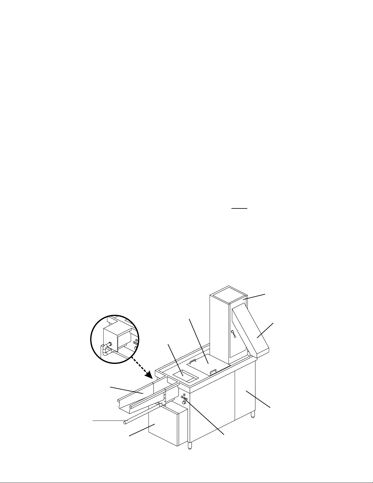
Figure 1-1: AZP 80 overview
Machines
without
feeding
trough
Feeding trough (if
so equipped -
supplied by others)
Recirculating
water line (if
equipped with
feeding trough)
Electrical
compartment
Manual
feeding
opening
Grinding
compartment
Water
separator
(inside tower)
Waste
chute
Machinery
compartment
Control
panel
Page 3
SECTION 1 - INTRODUCTION
1.2 General Safety Information
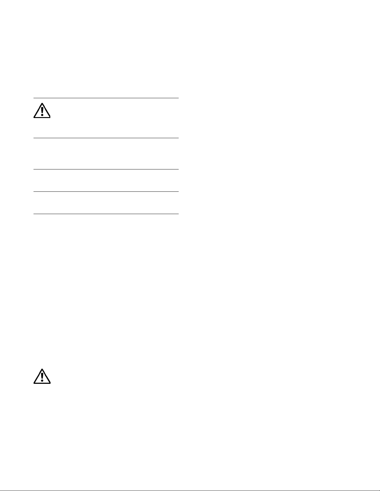
The following symbols and headings are used
throughout this manual to indicate possible
hazards to persons or to the equipment. The
symbols and headings are shown in order of
importance. The descriptive text following these
headings is italicized for easy recognition.
WARNING! Possible hazard to per-
sons, such as from electrical shock, crushing, or
hot surfaces.
CAUTION Possible hazard to the
dishwasher or to other
equipment.
IMPORTANT Vital information or tips for
the installer or operator.
NOTE Information or tips for the
installer or operator.
3INSTALLATION
3.1 Overview of Installation
The owner should contract with qualified
personnel to move the appliance to the
installation location, unpack it, and prepare
it for final utility connections. In most cases,
local codes prevent the final utility connections from being made by any party other
than a licensed electrician and/or plumber.
IMPORTANT
It is the responsibility of the owner to ensure
that all aspects of the installation comply with
all applicable local and national codes.
IMPORTANT
The appliance’s warranty is not valid until a
Meiko Authorized Service Agent performs a
Startup and Demonstration on the appliance.
This Demonstration should be scheduled after
the installation.
2TRANSPORT AND SHIPPING
IMPORTANT
• Observe any notices on the crating material that pertain to shipping.
• Use care when transporting the equipment.
• As you unpack the equipment, check that
all components shown on the shipping
invoice are present and intact. Be sure to
check for shipping damage. If shipping
damage is present, file a freight claim
immediately and inform Meiko of the
damage, identifying all affected parts.
WARNING!
In NO EVENT should a damaged appliance be installed or operated!
Installation of the waste pulper involves the
following steps:
• Verifying that the utility connections are
present, are appropriate for the appliance,
and comply with all applicable local and
national codes.
• Unwrapping the appliance (leaving the
shipping skid in place for easier movement) and checking for shipping damage.
• Moving the appliance to the installation
location, removing the skid, and leveling
the feet.
• Attaching a feeding trough (if so equipped).
• Connecting the electrical supply.
• Connecting the water supplies.
• Connecting the drain line, and routing it
to an appropriately-sized floor drain.
• Installing a deodorizing system (if so
equipped), following the manufacturer’s
instructions.
Page 4
• Contacting your Meiko Authorized Service
Agent to perform a Startup and Demonstration on the appliance. This step also
validates the appliance’s warranty.
SECTION 3 - INSTALLATION
3.2 Requirements Before Installation
Before the installer can uncrate and move the
appliance to the installation location, the following conditions MUST be met:
• INSTALLATION AREA REQUIREMENTS
- The area MUST be frost-free. Freezing temperatures (32°F/0°C or lower)
inhibit proper operation and can damage internal components.
- The area MUST have a firm floor surface. It is possible to compensate for
uneven flooring by adjusting the feet.
• UTILTITY CONNECTION REQUIREMENTS
- Connections must be present and
ready for hookup to the appliance. All
utility supplies must comply with the
electrical information labels, on the
data plate, and with all applicable local and national codes.
- Electrical leads and the water supply
lines (supplied by the customer) must
be present. The water supplies must
be of the pressure and temperature
specified on the data plate.
- For units equipped with an optional
trough feeding system, the trough
should be present, and must match the
requirements of the machine as per all
specification sheets and supplied
drawings.
- For units using a deodorizing system,
an appropriate dispenser or container
should be installed and ready for connection to the appliance.
• GENERAL REQUIREMENTS
Authorized personnel should be available
to perform the actual utility connections.
3.3 Uncrating, Positioning and Leveling
1. Remove all shipping and packaging material from the appliance, including supports and wrappings. Leave the shipping
skid in place at this time to allow for easier
movement to the installation location.
2. Check for shipping damage as described
in Section 2, Transport and Shipping.
If damage is present, call Meiko Customer
Service at 1-800-868-3840, providing full
details on the customer, serial number and
extent of damage present. Meiko will file
a freight claim based on this information.
3. Move the appliance to the installation area
and remove the skid. Meiko recommends
using a pallet truck to lift the entire pallet
and avoid damage to the machine. Use
caution to avoid damaging the appliance
or any of its components.
CAUTION
If the pallet is removed, the frame of the
machine can be damaged by improper
lifting. Always use wooden members to
properly distribute the machine’s weight
and avoid damage. Note that motors or
other components may extend below the
frame; use caution to avoid damaging
these components.
CAUTION
Do not attempt to slide the machine on its
feet. This may damage the feet or bend
the legs of the machine. Move the
machine to the installation location by
lifting it, using a palette truck with wooden
members to distribute the weight.
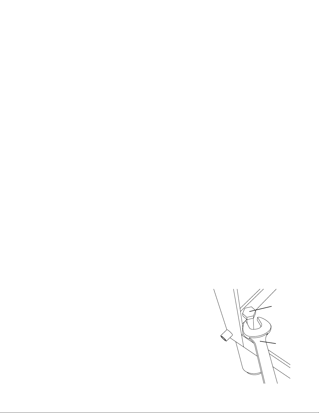
5. Using a spirit level, check that the
appliance is level in both directions (frontto-back AND side-to-side). If necessary,
level the appliance by accessing the bolts
above each foot and adjusting them using
a 17mm wrench. It is necessary to lift the
machine to remove the pressure from the
foot before adjustment. Refer to Figure 3-1.
CAUTION
The waste pulper MUST be level for
proper operation.
Figure 3-1:
Adjustment
bolt
Foot
adjustment
17mm
Open access doors or
remove side panels to
access adjustment bolts
Lift machine to remove
pressure before
adjusting foot
17mm
wrench
Page 5
SECTION 3 - INSTALLATION
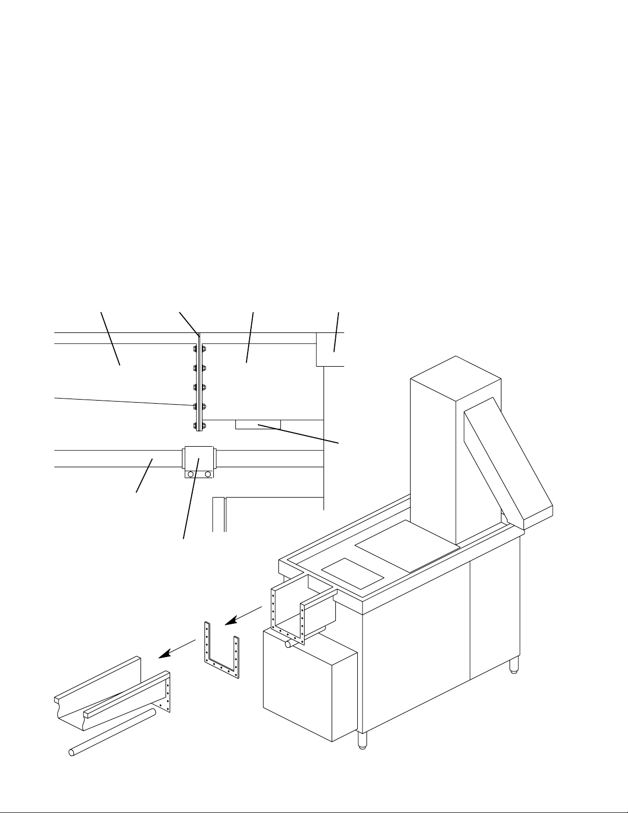
3.4 Connecting a Feeding Trough (if so
equipped)
Waste pulpers intended for use with a feeding
trough are equipped with a short trough
section at the load end of the machine. This
section incorporates a cutlery catch box,
magnet, and a mating plate. The end of the
trough (supplied by others), when constructed
to drawings supplied by Meiko, will
incorporate a matching plate to allow for
connection to the pulper.
Figure 3-2: Trough connection
Customer-
supplied
trough
Gasket
(supplied with
AZP 80)
Short trough
section (supplied
with AZP 80)
1. Attach the trough using qty. 13 hex bolts,
flat washers, lockwashers and hex nuts
as shown in Figure 3-2. Be sure to install
the supplied gasket between the mating
surfaces. Seal the connection with silicone
sealant to prevent water leakage.
2. Attach the recirculating water line to the
machine’s 2” OD pipe connection using
the supplied clamp and rubber boot.
AZP 80
Customer-supplied
recirculating water
line (2” OD)
Clamp fits over
rubber boot
Magnet
Page 6
 Loading...