

Meiko AZP80 User Manual
AZP 80
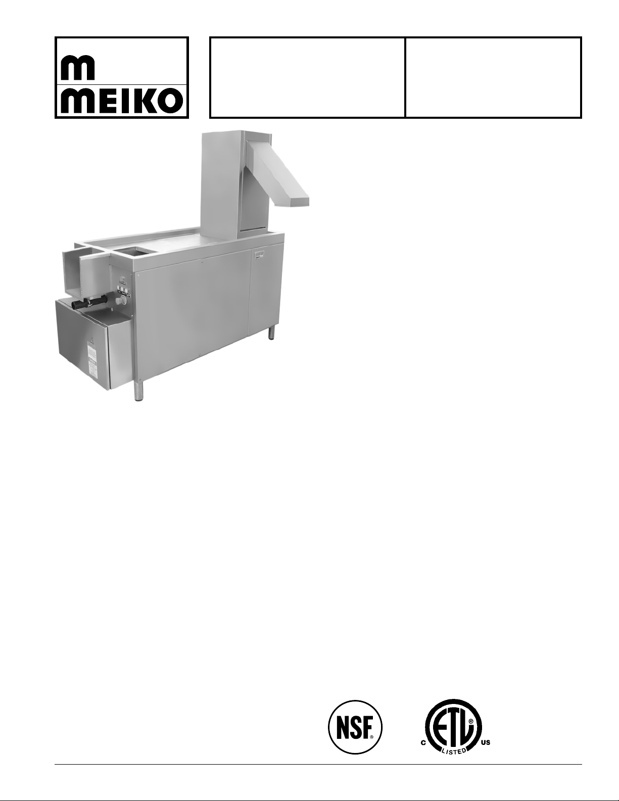
Meiko's AZP 80 is an advanced, high-capacity
waste pulper that reduces food and mixed waste
volume by up to 85%.
Normal kitchen waste, with its high water content,
is a recognized carrier for disease and odors. The
AZP 80 solves these problems by reducing food
waste to a dry, relatively odorless pulp, using a
vertical, side-mounted tungsten carbide grinding
mechanism and a vertical dewatering press. A
flushing mechanism keeps the unit operating at
maximum efficiency during peak loads.
Reducing waste volume also reduces labor
costs,as well as costs associated with waste
transportation, disposal and pest control.
As with all products synonymous with the name
“Meiko,” engineering excellence, manufacturing
quality and performance come to the forefront in
the AZP 80.
WASTE
PULPER
Standard Features:
• Processes food and mixed kitchen waste, including
styrofoam, paper, and cardboard
• Waste is reduced to a dry pulp, with a volume
reduction of 70-85%. Water and liquid waste is filtered
and drained
• Includes a vertical, side-mounted grinding mechanism
and a vertical dewatering press in one unit
• Waste can be loaded using a continuous flushing
trough, or manually
• Safety features prevent metal objects such as knives
and forks from entering the grinding mechanism
• Door safety switches protect the operator. The unit is
shut down automatically if the grinder or dewatering
press access doors are opened during operation
• Convenient, reliable electromechanical controls
• Powerful 8.8 hp grinding motor is mounted horizontally
for easy serviceability
• Grinding disk incorporates tungsten carbide cutters
• Vertical dewatering press chamber incorporates selfflushing system to ease cleanup
• Flush-paneled, stainless steel exterior
• Automatic water level control
• Built-in connection points for odor neutralizing pumps
AZP 80 • Updated 07-09 Meiko • 1349 Heil Quaker Blvd. • La Vergne, TN 37086 • (800) 55-MEIKO • FAX (615) 399-6620 • www.meiko.us
Options:
• Available in left-to-right or right-to-left configurations
• Available with or without external water trough and
water recirculation connections
• Choice of waste chute locations: front, rear or inline
• Choice of water circulation pumps to accomodate a
variety of flushing trough systems
• Separate control panel at remote location
D
H
C
1' 6-1/2" (470mm)
1' 9-5/8" (550mm)
2' 3/8" (620mm)
4-1/2"
(115mm)
2' 3-1/2" (700mm)
4' 11" (1500mm)
7-7/8"
(200mm)
5' 6-7/8" (1700mm)
5-7/8"
(150mm)
3' 5/8" (930mm)
5' 7-1/8" (1705mm)
2' 6-1/2" (775mm)
1' 10-1/8" (560mm)
1' 11-3/4" (605mm)
3' 6-1/8" (1070mm) 1' 3-3/4"
(400mm)
1' (304mm)
8-5/8"
(220mm)
1' 3-3/4" (400mm)
1-1/8"
(30mm)
1' 3-3/4" (400mm)
1-1/8" (30mm)
2" (50mm)
3-1/8" (80mm)
7-1/8"
(180mm)
2-3/4"
(70mm)
1' 3-3/4" (400mm)
R
5-5/8"
(143mm)
7-7/8"
(200mm)
Control
panel
Trough
(see inset
drawing)
5' 7-1/8" (1705mm) A.F.F.
1' 2-1/8"
(360mm)
1' 4-7/8"
(430mm)
5-1/4"
(133mm)
11-3/4"
(297mm)
Base of tower
2' 10-3/4" (880m) A.F.F.
2' 8-1/2" (825mm)
3' 9" (1145mm) A.F.F.
Top of machine lip
3' 5/8" (930mm) A.F.F.
1' 3-3/4" (400mm)
1' 3-3/4"
(400mm)
1' 4-3/8"
(415mm)
2-3/4"
(70mm)
10-1/4"
(260mm)
1' 6-1/2"
(470mm)
2' 7-1/2" (800mm)
2' 11-7/8" (909mm)
3-3/4"
(94mm)
HH
Water supply connections
Hot water (110-140°F/43-60°C)
3/4" NPT male connection. 36-72
PSI (2.5-5.0 bars). Consumption
31.7 US gals. (120 l)/hr.
Trough
(supplied
by others)
1' 7-3/4"
(500mm)
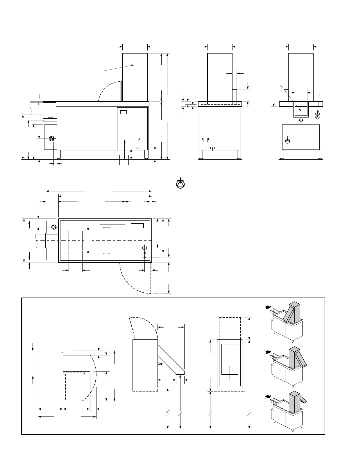
Plan view
Left side viewRight side viewFront view
Dewatering press tower
AZP 80 Left-to-Right
Units with recirculating trough
5-3/8"
(137mm)
2' 3/4" (630mm)
1-3/8"
(35mm)
RR
Recirculating trough
connection
2" (51mm) O.D. connection via
clamp (provided). Route piping to
beginning of water trough. Piping
must incorporate 2" ball valve for
regulation of trough water supply.
Chute can be specified to
discharge to the front, inline
or rear at time of order. Door
can be hinged on either side
(left hinge is shown).
Plan view
Chute can be
specified to discharge
to the front, inline or
rear at time of order.
See detail drawings
for dimensions.
All dimensions from floor
are +/- 1/2" (12mm)
due to adjustable feet.
All
dimensions
from floor are
+/- 1/2"
(12mm) due
to adjustable
feet.
2' 3-1/2" (700mm)
2" (51mm)
1' 7/8" (327mm)
D
H,C
6-3.4"
(171mm)
1' 1/2"
(318mm)
CDH
R
R
Cold water (50°F/10°C)
3/4" NPT male connection. 36-72
PSI (2.5-5.0 bars). Initial fill 21.1
US gals. (80l). Consumption 39.6
US gals. (150 l)/hour
CC
Front
chute
Inline
chute
Rear
chute
DD
Electrical supply connection
4-wire (L1, L2, L3, GND)
connection without neutral.
Supply routed from below the
machine (strain relief provided).
Individual circuit breaker/
disconnect with lockout/tagout
strongly recommended.
Drain connection
2" NPT female vertical drain
outlet (HDPE piping).
Recommended placement
directly above 3" (75mm) floor
drain. Grease trap/separator
required (provided by others).
AZP 80 • Updated 07-09 Meiko • 1349 Heil Quaker Blvd. • La Vergne, TN 37086 • (800) 55-MEIKO • FAX (615) 399-6620 • www.meiko.us
Recirculating Trough Connection
Downslope
required
(1-1/4" per 10'
suggested
minimum)
(trough to be supplied by others)
3/4"
(20mm)
All dimensions
from floor
are +/- 1/2"
(12mm) due to
adjustable feet.
Front
view
"Step" down to attached stub
trough forms cutlery catch box
(magnet is supplied)
Magnet
2' 3-1/2" (700mm)
Left-to-Right
operation shown.
Right-to-Left
is a mirror image.
2" clamp
provided for
recirculating
water pipe
connection
1' 11-3/4" (605mm)
3/4"
(20mm)
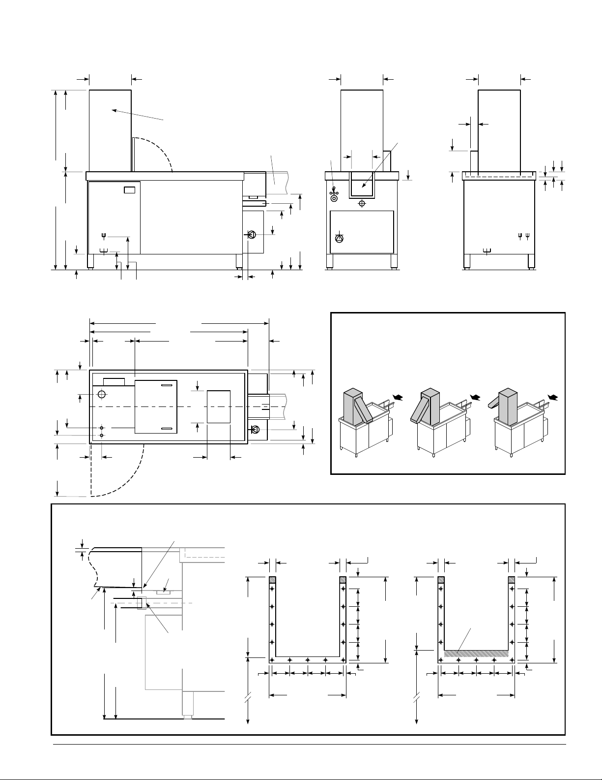
AZP 80 Right-to-Left
Units with recirculating trough
Front
chute
Inline
chute
Rear
chute
D
H
C
9"
(230mm)
1' 9-5/8" (550mm)
2' 3/8" (620mm)
4-1/2"
(115mm)
2' 3-1/2" (700mm)
4' 11" (1500mm)
7-7/8"
(200mm)
5' 6-7/8" (1700mm)
5-7/8"
(150mm)
3' 5/8" (930mm)
5' 7-1/8" (1705mm)
2' 6-1/2" (775mm)
1' 10-1/8" (560mm)
1' 11-3/4" (605mm)
3' 6-1/8" (1070mm)1' 3-3/4"
(400mm)
1' (304mm)
8-5/8"
(220mm)
1' 3-3/4" (400mm)
1-1/8"
(30mm)
1' 3-3/4" (400mm)
1-1/8" (30mm)
2" (50mm)
3-1/8" (80mm)
7-1/8"
(180mm)
2-3/4"
(70mm)
R
R
1' 3-3/4" (400mm)
R
5-5/8"
(143mm)
7-7/8"
(200mm)
Control
panel
Trough
(see inset
drawing)
Trough
(supplied
by others)
1' 7-3/4"
(500mm)
Plan view
Left side viewRight side viewFront view
2' 3/4" (630mm)
1-3/8"
(35mm)
Chute can be
specified to discharge
to the front, inline or
rear at time of order.
See detail drawings
for dimensions.
All dimensions from floor
are +/- 1/2" (12mm)
due to adjustable feet.
2' 3-1/2" (700mm)
2" (51mm)
1' 7/8" (327mm)
D
H,C
6-3.4"
(171mm)
1' 1/2"
(318mm)
C
D
H
1' 10-1/8" (563mm)
R
2-3/16"
(56mm)
3/8" (10mm)
9-7/16" (244mm)
10-5/8" (270mm)
2-3/16"
(56mm)
2-3/16"
(56mm)
2-3/16"
(56mm)
1-1/2" (37mm)
2-3/16"
(56mm)
2-3/16"
(56mm)
2-3/16"
(56mm)
2-3/16"
(56mm)
3/8"
(10mm)
9-13/16" (250mm)
trough depth
2' 2-3/4" (680mm) A.F.F.
3/8"
(10mm)
13/16"
(20mm)
7-7/8" (200mm)
13/16" (20mm)
squared edge
2-3/16"
(56mm)
3/8" (10mm)
9-7/16" (244mm)
10-5/8" (270mm)
2-3/16"
(56mm)
2-3/16"
(56mm)
2-3/16"
(56mm)
1-1/2" (37mm)
2-3/16"
(56mm)
2-3/16"
(56mm)
2-3/16"
(56mm)
2-3/16"
(56mm)
3/8"
(10mm)
9-1/16" (230mm)
trough depth
2' 3-1/2" (700mm) A.F.F.
3/8"
(10mm)
13/16"
(20mm)
7-7/8" (200mm)
13/16" (20mm)
squared edge
Customer-supplied
trough flange includes
20mm additional
material to form wall
of cutlery catch box
Detail view: AZP 80 flange
(supplied with machine)
Detail view: trough flange
(to be supplied by others)
Dewatering press tower
For tower dimensions, refer to the facing page.
AZP 80 • Updated 07-09 Meiko • 1349 Heil Quaker Blvd. • La Vergne, TN 37086 • (800) 55-MEIKO • FAX (615) 399-6620 • www.meiko.us
 Loading...