

1/2-inch Miniature Color Camera
SI-C600N/SI-C600P
OPERATING MANUAL
For Customer Use :
Please record the model No. and the serial No.
in the spaces provided below. These numbers
located on the bottom of the camera.
Retain this information for future reference.
Model No. Serial No.
CAUTION
RISK OF ELECTRIC SHOCK
DO NOT OPEN
CAUTION : TO REDUCE THE RISK OF ELECTRIC SHOCK, DO NOT
REMOVE COVER (OR BACK).
NO USER SERVICEABLE PARTS INSIDE.
REFER SERVICING TO QUALIFIED SERVICE PERSONAL.
This lightning flash with arrowhead
symbol is intended to alert the user to
the presence of uninsulated "dangerous voltage " within the product's
enclosure that may be of sufficient
magnitude to constitute a risk of
electric shock to persons.
This exclamation p o i n t s y m b o l i s
intended to alert the user to the
presence of importan t operating
and maintenance (servicing) instruc
!
Due to design modification, data given in this
instruction book are subject to possible change
without prior notice.
-tions in t h e literature accompanying
the appliance.
!
WARNING :
TO PREVENT THE RISK OF FIRE OR
ELECTRIC SHOCK HAZARD, DO NOT
EXPOSE THIS CAMERA TO RAIN OR
MOISTURE.
Information for USA
This device complies with Part 15 of the
FCC Rules.
Changes or modifications not approved by
COSTAR could void the user's a u t h o r i t y to
operate the equipment.
1

Thank you for purchasing this color video camera. Before using this camera, please read this operation
manual carefully to obtain the best result and keep this manual for future reference.
CCCCOOOONNNNTTTTEEEENNNNTTTTSSSS
SAFETY INSTRUCTIONS
PRECAUTIONS
FEATURES
. . . . . . . . . . . . . . .
. . . . . . . . . . . . . . . . . .
NAME AND FUNCTIONS
MENU SYSTEM
Menu Description . . . . . . . . . . . . . . 10
Setup Menu . . . . . . . . . . . . . . . . . 11
Lens . . . . . . . . . . . . . . . . . . . . . 11
Shutter/AGC . . . . . . . . . . . . . . . . . 12
White Balance . . . . . . . . . . . . . . . 13
Back Light . . . . . . . . . . . . . . . . . 14
Picture Adjust . . . . . . . . . . . . . . . 15
ATR . . . . . . . . . . . . . . . . . . . . . . 15
Motion Detection . . . . . . . . . . . . . . 16
Privacy . . . . . . . . . . . . . . . . . . . 17
Day/Night . . . . . . . . . . . . . . . . . . 17
Noise Reduction . . . . . . . . . . . . . . 19
. . . . . . . . . . . . . . .
. . . . . . . .
. . . . . . . .
3
4
5
6
9
Camera ID . . . . . . . . . . . . . . . . . 19
Sync . . . . . . . . . . . . . . . . . . . . 20
Language . . . . . . . . . . . . . . . . . . 20
Camera Reset/ Save All . . . . . . . . . 21
INSTALLATION (LENS)
Mounting a lens . . . . . . . . . . . . . . 23
Back-focus adjustment . . . . . . . . . . 24
Lenses that can be used . . . . . . . . . 25
INSTALLATION (CAMERA)
Installation . . . . . . . . . . . . . . . . . 26
CONNECTIONS
SPECIFICATIONS
. . . . . . . . . . . . . .
. . . . . . . . . . . . .
SUPPLIED ACCESSORIES
MEMO
. . . . . . . . . . . . . . . . . . . .
. . . . . . . . .
. . . . . .
. . . . . . .
22
26
27
28
29
30
2
SAFETY INSTRUCTIONS
1. Read Instructions
Read all of the safety and operating instructions
before using the product.
2. Retain Instructions
Save this instructions for later use.
3. Cleaning
Unplug this appliance from wall outlet before
cleaning. Do not use liquid cleaners or aerosol
cleaners. Use a damp cloth for cleaning.
4. Attachments
Do not use attachments not recommended by
the appliance manufacturer as they may cause
hazards
5. Water and Moisture
Do not use this product near water or moisture.
(For example, near a bathtub, wash bowl, kitchen
sink, or laundry tub, in a wet basement, or near
a swimming pool, etc.)
6. Installation
Do not place this product on an unstable cart,
stand, or table. The product may fall, causing
serious injury to a child or adult, and damage to
the product.
Use only with a cart or stand recommended by
the manufacturer, or sold with the product.
Mounting are should follow the manufacturer's
instructions,and should use a mounting accessory
recommended by manufacturer.
7. Moving
Product and cart combination
should be moved with care.
Quick stops, excessive force,
and uneven surfaces may cause
the product and cart combination
to overturn.
8. Ventilation
Slots and openings in the cabinet and the back
or bottom are provided for ventilation, and to
insure reliable operation of the product and to
protect it from overheating, and these openings
must not be blocked or covered.
The openings should never be blocked by plac
-ing the product on a bed, sofa, rug, or other
similar surface. This product should not be
placed in a built-in installation such as a book
-case unless proper ventilation is provided.
9. Power source
This product should be operated only from the
type of power source indicated on the marking
label. If you are not sure of the type of power
supplied to your home, consult your dealer or
local power company.
3

PRECAUTIONS
Operating
●
Before using make sure of power supply and
connection of video output.
Power supplied without voltage stabilization or
the voltage maintained at 12VDC±10% may
cause damage.
●
While operating, if any abnormal condition or a
malfunction is observed, stop using the camera
immediately then call your local dealer.
Handling
●
Do not disassemble the camera and never
touch parts inside the camera.
●
Do not drop the camera or subject it to shocks
and vibrations to avoid possible damage.
●
When attaching or removing the lens, handle
with care moisture and dust does not enter
the camera.
●
Do not shoot any source of bright light. if the
object contains very bright areas, bright vertical
or horizontal lines may appear on the screen.
This is called "smear", a phenomenon which
often occurs with solid-state pickups, and is not
a malfunction.
Installation and storage
●
Do not point the camera at the sun. This could
damage the camera whether it is operating or
not.
●
Do not install the camera where the temperature could exceed the allowable range.
Be sure the ambient temperature is less than
40℃in installations intended for long term
continuous operation.
●
Avoid installing in a humid or dusty plase.
●
Avoid installing in places where there is radiation. This could damage sensor and other
components and cause a malfunction.
●
Avoid installing in places where there are
strong magnetic fields and electric signals.
●
Avoid installing in places where the camera
would be subject to strong vibrations.
●
Never expose the camera to rain and water.
Cleaning
Turn the power off and wipe off the dirt with a
dry soft cloth. If it is extremely dirty, use furniture
cleaning tissue. Do not use alcohols, petroleum
distillates, liquid cleaners or sprays.
Daily check
Make daily check for proper operation for surveil
-ance use. In order to maintain normal operation,
the output of camera should be checked by
user everyday for a clear and focused picture.
FEATURES
High sensitivity
1/2" 412,000 pixels CCD with on-chip micro lenses
and low noise digital signal processing circuit
provide maximum sensivity down to 0.05 lux @
F1.2,50IRE.
High quality image
●
High resolution, high sensitivity design for a
horizontal resolution of 540TV lines.
●
High quality image is obtained by digital signal
processing with optimization of control program
and image correction algorithm.
Back Light (BLC & HLC)
When strong light entering the scene background
such as from a spotlight or window, back light
compensation function automatically adjust the
video level so as to preserve visibility in important
sections of the image.
White Balance
Seven white balance control modes can be sele
-selected according to conditions.
4
Iris function
Provide a drive output for video iris lens and DC
iris lens.
shutter speeds up to 1/100,000sec.
CCD iris function to automatically set the brightness of the picture by changing the shutter speed
of the camera according to the incident light when
using a manual iris lens.
Other versatile functions
●
Camera ID function of up to 24 characters.
●
Motion detection, Noise reduction and Privacy
functions are provided.
●
Picture adjustment for Mirror,Brightness,Contrast,
Sharpness, HUE, Gain..
●
Use either C or CS mount lenses.
Note :
Also built-in electronic shutter to allow 8
You must install a UPS system for safe
operation in order to prevent damage
caused by an unexpected power stopp
!
-age.
5

NAME AND FUNCTIONS
Lens mount
Mount for installing the lens. C-mount lens
can be used when C-mount adapter is attached, and CS-mount lens can also be
used when it is removed.
Lens mount cap
Be sure to cap the lens mount
when the lens is not mounted.
Back-focus screw
A screw is provided to fix the lens
mount. See page 24.
C-mount adapter
To mount a C- mount lens. And
remove to mount a CS-mount lens.
Turn counterclockwise to remove
it. Also refer to page 23.
Tripod mounting base
Mounting base for installing the
camera.
Power indicator
Lights up when the camera
is powered.
Video output connector
BNC connector that outputs
a composite video signal.
Setup buttons
When use setting up and
adjusting the camera with
reference to the on-scree n
menu.
See page 9.
▲
▼
6
◀ ▶
S-VIDEO connector
Output connector for separat
-ed Y/C video signal.
Connect to the S-VIDEO input
connector of video monitor,
See page 22.
S-VIDEO
Lens connector
When using an auto-iris lens,
connect the lens cable to this
connector.
See page 8.
Power input terminal
Connect to a DC 12V power
power source.
(Be sure not to connect the
power source until a l l other
connections are completed.)
7
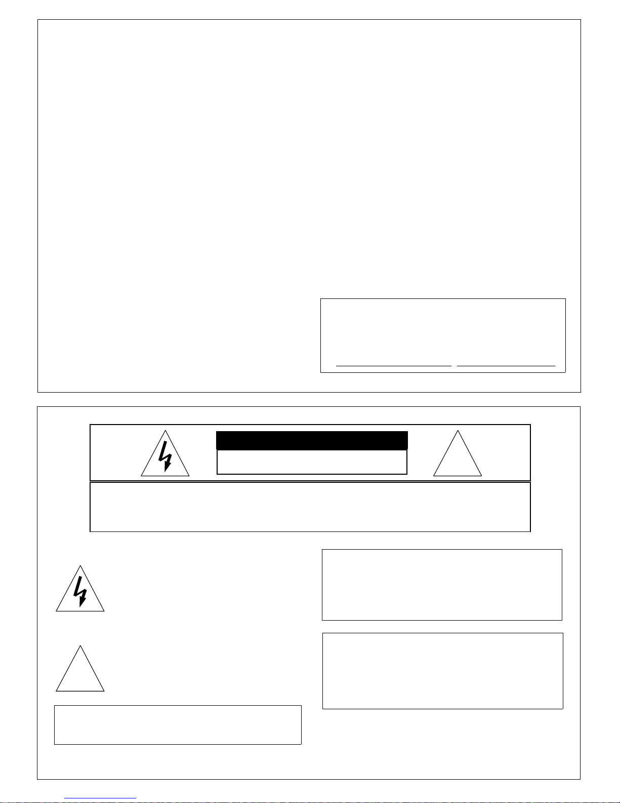
Lens Connector
DC type lens ;
Connect thelens cable of a DC (galvanometric) type lens. If the plug on the cable is of a
different type, replace it with the provided 4pin iris plug.
Damping coil (-) Drive coil (+)
① ③
② ④
Damping coil (+) Drive coil (-)
Pin Assignment : DC type (4-pin)
1 3
2 4
Pin No. Signal
1
Damping coil (-)
2
Damping coil (+)
3
Drive coil (+)
4
Drive coil (-)
After installing the connector plug, connect it to
the lens connector on the rear panel of camera.
MENU SYSTEM
GENERAL
The menu system can activate all the features
and option of the camera.
The menus are superimposed on the image displayed on the screen. The commands can open
other menus, toggle options, or change variable
parameters.
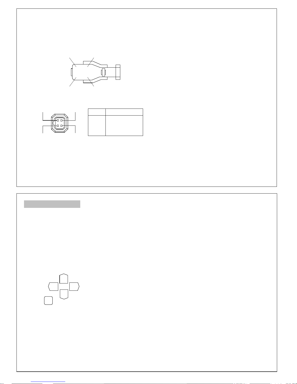
MENU OPERATION
Five rear panel Setup buttons are used to shift
the cursor and select items from the menus.
①①①①
③③③③ ④④④④
②②②②
⑤⑤⑤⑤
Setup buttons
8
The camera settings and adjustments can be
changed to accommodate usage conditions.
When connected to a monitor, convenient onscreen menus facilitate checking and changing
the settings and adjustments.
A brief help lines is often presented on the
screen below the list of commands.
The complete set of current parameters is saved,
and will be loaded each time turn on the camera
until the next time change the setup.
The setting menus are illustrated on the next
page.
①
Up button : Shift the cursor upwards.
②
Down button : Shift the cursor downwards.
③
Left button : Shift the cursor toward the left.
④
Right button : Shift the cursor toward the right.
⑤
Set button : To display the main menu or
check the setting and proceed
to the next item.
9

Menu Description
Shutter/AGC
(page 12)
●
AUTO
●
MANUAL
PRIVACY
(page 17)
●
OFF
●
ON
WHITE
BALANCE
(page 13)
●
ATW
●
PUSH
●
USER1~2
●
ANTI CR
●
MANUAL
●
PUSH LOCK
DAY/
NIGHT
(page 17)
●
AUTO
●
COLOR
●
BW
SETUP MENU
(page 11)
BACK
LIGHT
(page 14)
●
OFF
●
BLC
●
HLC
NOISE
REDUCTION
(page 19)
●
Y LEVEL
●
C LEVEL
CAMERA
ID
(page 19)
●
OFF
●
ON
PICT
ADJUST
(page 15)
●
MIRROR
●
Brightness
●
Contrast
●
Sharpness
●
HUE
●
GAIN
Lens (page 11)
●
AUTO
●
MANUAL
SYNC
(page 20)
●
INT
ATR
(page 15)
●
OFF
●
ON
LANGUAGE
(page 20)
●
ENGLISH●JAPANESE
●
GERMAN
●
RUSSIAN
●
PORTUGUESE
MOTION
DETECTION
(page 16)
●
OFF
●
ON
CAMERA
RESET
(page 21)
●
FRENCH
●
SPANISH
SAVE
ALL
(Page 21)
SETUP MENU
1) Press the Set button to display the Setup menu
on the monitor screen.
2) Check the present settings at the Setup menu.
SETUP MENU
LENS AUTO
SHUTTER/AGC AUTO
WHITE BAL ATW
BACKLIGHT OFF
PICT ADJUST
ATR OFF
MOTION DET OFF
NEXT
EXIT SAVE ALL
Setup menu
3) If changes are unnecessary, shift the cursor to
the EXIT position and press the Set button to
return the normal video screen.
4) When a setting is changed by pressing the Setup
buttons, the new setting is stored in the internal
memory by pressing the Set button with position
the cursor at SAVE ALL.
Afterwards, when the camera power is cut off
and returned, operation pro ceeds at the most
recent settings.
10
LENS
1) Press the Set button to display the Setup menu.
2) Position the cursor at LENS and press the left
or right button to select the Lens mode.
SETUP MENU
LENS AUTO
SHUTTER/AGC AUTO
WHITE BAL ATW
BACKLIGHT OFF
PICT ADJUST
ATR OFF
MOTION DET OFF
NEXT
EXIT SAVE ALL
3) Position the cursor at AUTO and press the Set
button to setting for Auto Iris Lens.
AUTO IRIS
TYPE DC
MODE AUTO
SPEED 080
RETURN
4) Press the Left, Right, Up,Down button to setting
the Lens.
After setting, position the cursor at
press the Set button to return to Setup Menu.
RETURN
and
11

SHUTTER/AGC
1) Press the Set Button to display the Setup menu.
2) Position the cursor at SHUTTER/AGC and press
the left or right button to select the Auto mode
or Manual mode setting.
AUTO Mode
When using the
the picture image will be controled by setting the
Brightness level.
AUTO SETUP
HIGH LUMINANCE
MODE SHUT+AUTO IRIS
BRIGHTNESS
LOW LUMINANCE
MODE AGC
BRIGHTNESS x0.50
RETURN
In SHUT+AUTO IRIS mode, shutter speed is
matically varied acccording to the incident light.
-
The brightness indicates DC level of DC lens in High
Luminance mode.
In Low Luminance mode, brightness indicates AGC
level.
ris lens, the brightness of
Auto I
024
auto
MANUAL Mode
When using the
Manual I
ris lens, the brightness of
the picture image will be controled by setting the
shutter level.
MANUAL SETUP
MODE SHUT+AGC
SHUTTER 1/60
AGC x6.00
RETURN
In Manual mode, Shutter and AGC level will be
changed as follows.
Shutter : 1/60 to 1/100,000sec (8 stage)
AGC level : 6dB to 44.8dB (8 stage)
Note :
Outdoor illumination levels may exceed
150,000 lux, which is outside the range
that can be controlled by the electronic
!
shutter. For proper operation of elect
-ronic shutter, If illumination levels exceed 10,000 lux, use a auto-iris lens.
WHITE BALANCE
1) Press the Set button to display the Setup menu.
2) Position the cursor at LENS and press the left
or right button to select the white balance mode.
SETUP MENU
LENS AUTO
SHUTTER/AGC AUTO
WHITE BAL ATW
BACKLIGHT OFF
PICT ADJUST
ATR OFF
MOTION DET OFF
NEXT
EXIT SAVE ALL
Seven white balance control modes can be selected
according to conditions.
ATW :
Automatically tracks the changes in the color temp
-perature, and adjusts the white balance.
ATW
SPEED 239
DELAY CNT 016
ATW FRAME x2.00
ENVIROMENT INDOOR
RETURN
12
SPEED : Adjusts the pull-in speed of ATW.
DELAY CNT : Sets the time-based hysteresis of
ATW.
ATW FRAME : Sets the pull-in frame magnification.
ENVIROMENT : Sets the pull-in frame of ATW.
(indoor or outdoor)
PUSH :
Adjusts the white balance regardless of the subject
condition.(Pull-in mode)
USER1 :
Manually adjusted white balance by User mode1.
USER2 :
Manually adjusted white balance by User mode2.
ANTI CR :
Minimizes the color changes(color rolling) over long
periods caused by very small differences between
the flicker frequency of non-inverter fluorescent lights
and the drive frequency of the image sensor devices.
MANUAL :
Function allows the white balance to be adjusted
manually following the black body radiation curve.
The R gain is adjusted automatically in tandem with
the up/down setting of the B gain.
PUSH LOCK :
Function for locking the WB gain after PUSH(pull-in)
control and shutting down the pull-in control.
13

BACKLIGHT
Two backlight modes can be selected according to
conditions.
SETUP MENU
LENS AUTO
SHUTTER/AGC AUTO
WHITE BAL ATW
BACKLIGHT BLC
PICT ADJUST
ATR OFF
MOTION DET OFF
NEXT
EXIT SAVE ALL
BLC Mode
The backlight compensation function provides com
-pensation by increasing the brightness of the
overall screen so that subjects being shot with a
loss of dark detail due to backlight will have just
the right brightness level.
The execessive front lighting compensation function
provides compensation by reducing the brightness
of the overall screen so that subjects being shot
which are overexposed due to excessive front lighting
will have just the brightness level.
HLC Mode
High light compensation is a function that improves
the visual recognition of license plates and other
such objects by suppressing or marsking strong light
sources(such as headlights of automobiles) in dark
places.
PICTURE ADJUST
1) Press the Set button to display the Setup menu.
2) Position the cursor at PICT ADJUST and press
the
MIRROR : Sets the horizontal flip for the display
BRIGHTNESS : Sets the brightness of video output
CONTRAST :
SHARPNESS : Sets the sharpness of video output
HUE : Sets the HUE(color) of video output signal.
GAIN : Sets the chroma gain of video output signal.
button to adjust the video output signal.
Set
PICT ADJUST
MIRROR OFF
BRIGHTNESS 000
CONTRAST 128
SHARPNESS 128
HUE 128
GAIN 128
RETURN
output.
signal.
Sets the contrast of video output
signal.
signal.
14
ATR (Adaptive Tone Reproduction)
ATR function provides gradation compensation to
improve the contrast of subjects whose gradation
has been lost in cases where, for instance, both
low-luminance areas and high-luminance areas exist
in the same picture.
The ATR function improves the visibility of the entire
picture by providing the optimum gradation compensation for the image in one field based on the
luminance information.
1) Press the Set button to display the Setup menu.
2) Position the cursor at ATR and press the left or
right button to ATR mode ON.
SETUP MENU
LENS AUTO
SHUTTER/AGC AUTO
WHITE BAL ATW
BACKLIGHT OFF
PICT ADJUST
ATR ON
MOTION DET OFF
NEXT
EXIT SAVE ALL
15

MOTION DETECTION
By using the motion detection function, it is possible
to create surveillance cameras which are capable
of detecting moving objects.
The motion detection function identifies motion and
outputs motion information when the difference in
brightness exceeds a specific level between frames
(2VD).
1) Press the Set button to display the Setup menu.
2) Position the cursor at MOTION DET and press
the
function.
DETECT SENSE : Sets the motion detection sen
BLOCK DISP : Control of the motion detection block
button to setting the motion detection
Set
MOTION DET
DETECT SENSE 111
BLOCK DISP OFF
MONITOR AREA ON
AREA SEL 1/4
TOP 000
BOTTOM 000
LEFT 000
RIGHT 000
RETURN
-sitivity.
display.
MONITOR AREA : Sets whether to use the moni
-toring frames.
AREA SEL : Selects the monitoring frame to be set.
TOP : Sets the top side of the monitoring frame.
BOTTOM : Sets the bottom side of the monitoring
frame.
LEFT : Sets the left side of the monitoring frame.
RIGHT : Sets the right side of the monitoring frame.
PRIVACY
This function is to make lest the specific part should
be seen on the screen.
1)
Position the cursor at Privacy and press the left,
right button to set Privacy ON.
2)
Press the Set button to enter the Privacy setup.
PRIVACY
AREA SEL 1/4
TOP 000
BOTTOM 000
LEFT 000
RIGHT 000
COLOR 1
TRANSP 1.00
MOSAIC OFF
RETURN
AREA SEL : Selects the mask frame to be adjusted.
TOP : Sets the top side of the mask frame.
BOTTOM : Sets the bottom side of the mask frame.
LEFT : Sets the left side of the mask frame.
RIGHT : Sets the right side of the mask frame.
COLOR : Sets the color of the mask frames.
TRANSP : Sets the transparency ratio of the mask
frames.
MOSAIC : Sets the mask frame mosaic function.
16
DAY/NIGHT
Day/Night function improves the camera's sensitivity
at night or when the brightness level of the ambient
environment is otherwise low by removing the
infrared filter and enabling the camera to shoot with
the wavelengths of the incident light extending up
to the infrared region.
Three Day/Night modes can be selected according to
conditions.
●
COLOR
Day/Night function is set to OFF.
●
B/W
Night mode established forcibly, and chroma is
set to OFF.
●
AUTO
Day or Night function is automatically identified and
controlled according to illumination condition.
SETUP MENU
PRIVACY OFF
DAY/NIGHT AUTO
NR
CAMERA ID OFF
SYNC INT
LANGUAGE ENGLISH
CAMERA RESET
BACK
EXIT SAVE ALL
17

AUTO Mode :
1) Position the cursor at Day/Night and press the left
or right button to change the Day/Night mode.
2) Press the Set button only when position the cursor
at Auto to adjust the Day/Night function control.
DAY/NIGHT
BURST ON
DELAY CNT 010
DAY->NIGHT 003
NIGHT->DAY 005
BW Mode :
1) Press the Set button only when position the cursor
at BW to adjust the BW mode control.
BW
BURST ON
IR OPTIMIZER ON
MODE AUTO
LEVEL 015
RETURN
RETURN
BURST : Selects whether to output the burst signal
when the night status has been identified.
DELAY CNT : Sets the Night/Day identification
transfer time.
DAY->NIGHT : Sets the threshold for identifying the
Night status from the Day status.
NIGHT->DAY : Sets the threshold for identifying the
Day status from the Night status.
NOISE REDUCTION
Noise reduction is a function that reduces the image
noise in order to improve the image quality of the
camera.
In particular, it reduces the noise whichis generated
under low-brightness shooting conditions and other
high-gain states.
1) Position the cursor at NR and press the Set
button to setting the noise reduction function.
NR
NR MODE Y/C
Y LEVEL 004
C LEVEL 004
RETURN
2) Press the cursor at NR MODE and press the left
or right button to change the NR mode.
Y/C : Y and C filter ON.
Y : Y filter ON.
C : C filter ON.
Y LEVEL : Sets the Y filter strength.
C LEVEL : Sets the C filter strength.
2) Press the left / right / up / down button to select a
BW mode control.
BURST
: Selects whether to output the burst
signal when the BW status has been
identified.
IR Optimizer Function :
If, when the Night operation mode of the Day/Night
function is established, the mode is used together
with an external infrared LED light source, excessive
front lighting may occur, resulting in over exposure.
The IR Optimizer function makes it possible to
minimize this overexposure by optimizing the ex
-posure control during Night operations.
18
CAMERA ID
When the internal OSD menu display is hidden in the
internal mode, it is possible to display the Camera
ID on-screen.
Any character string consisting of two rows(vertical)
of up to 26 characters(horizontal) on each row can
be used for the Camera ID, and it can be displayed
at any position on the screen.
1) Position the cursor at
CAMERA ID
Set button to setting the Camera ID.
CAMERA ID
ABCDEFGHIJKLMNOPQRSTUV
WXYZ0123456789-!"#$%&'
()_‘,¥:;<=>?@
←→↑↓ CLR POS
EXIT
^*.x+/
\
2) Press the left / right / up / down button to select a
character and press the Set button to camera ID
generation
.
3) Press the Set button to camera ID position set
when position the cursor at POS.
4) Press the left/ right/ up/ down button to move the
camera ID position.
and press the
19

SYNC (Internal Only)
This function is used to display the current synchro
-nization mode.
When the line lock mode is being used as the
synchronization mode, it is possible to adjust the
phase in the vertical direction.
1) Position the cursor at SYNC and press the left or
right button to select the Sync mode.
SETUP MENU
PRIVACY OFF
DAY/NIGHTT AUTO
NR
CAMERA ID OFF
SYNC
LANGUAGE ENGLISH
CAMERA RESET
BACK
EXIT SAVE ALL
2) Press the Set button only when position the cursor
at LL to adjust the line lock phase.
LL
PHASE 326
RETURN
LL
LANGUAGE
The OSD menu displays support 7 languages ;
English,Japanese,German,French,Russian, Spanish
and Portuguese.
Position the cursor at LANGUAGE and press the
left,
right button to select a language.
The menus can be changed in real time in the
selected language.
MENU CONFIGURATION
CONFIDENTIAL OFF
JOUR/NUIT AUTO
REDUCT BRUIT
ID CAMERA OFF
SYNC INT
LANGUAGE FRANCAIS
REINIT. CAMERA
BACK
QUITTER SAVE ALL
Adjusts the phase in the vertical direction when
the line lock mode is eastablished.
CAMERA RESET
This function initializes all the OSD menu settings
together.
Position the cursor at CAMERA RESET and press
the Set
button to camera reset.
SETUP MENU
PRIVACY OFF
DAY/NIGHT AUTO
NR
CAMERA ID OFF
SYNC INT
LANGUAGE ENGLISH
CAMERA RESET
BACK
EXIT SAVE ALL
SAVE ALL
This function is used to save the various settings
of the OSD menu in the EEPROM together.
SAVE ALL is always displayed on the bottom line
of the top menu.
20
21

INSTALLATION (LENS)
■■■■
Please attach a lens cable
when using the DC iris lens
Pin assignment : S-VIDEO connector (4-pin)
4 3
2 1
Pin No. Signal
1
GND
2
GND
3
Y (Luminance,
1Vp-p, 75Ω)
4
C (Chrominance,
0.286Vp-p, 75Ω)
Mounting a lens
①
Remove the lens mount cap from the camera.
②
Attach or remove the C-mount adapter depending on the lens to be used.
●
If the adapter is attached so tightly that is
difficult to remove, use long-nosed pliers to
remove it. Insert the tips of the pliers into the
holes with no threads, thus turn to remove.
Or a screwdriver can also be used, as shown.
Insert M3 screws into the holes so that the
screwdriver has something to grip. (Store the
C-mount adapter for possible future use.)
22
●
When installing a galvanometric-iris lens, lens
switch should be set to DC position.
ADJUSTING AUTO-IRIS LENSES
Make this adjustment after connecting the
camera to a power source and a monitor.
1) Set AGC mode to off.
2) When using a Video type lens :
Adjust the level control on the lens to pro-
duce minimum smear and optimum pictures.
3) When using a DC type lens :
Adjust the video level control on the main
menu to produce minimum smear and optimum pictures.
4) Set AGC mode to on
It is recommended that the AGC be used in
the "on" mode after adjusting the video
level.
③
Attach the lens to the lens mount. Secure it so
that it does not become loose.
④
If the lens has an auto-iris mechanism, connect
the lens cable to the lens connector.
●
When installing a video-iris lens, lens switch
should be set to VIDEO position.
23

Back-focus adjustment
When a lens is mounted, adjustment of the
back-focus may sometimes be required. Adjust
the lens
focus ring when the correct focus cannot be obtained.
WITH A FIXED-FOCUS LENS
1) Fully open the aperture and set the focus ring
to "∞" (infinity).
In the case of an auto-iris lens only, shoot a
comparatively dark object so that the aperture is
fully open.
2) Loosen the two back-focus screw with a hex
wrench, and turn the lens mount to focus.
3) After adjusting the back-focus, tighten the backfocus screw.
Back-focus screw
WITH A ZOOM LENS
1) Fully open the aperture and set the lens to the
maximum tele-photo position. Then turn the focus
ring to focus.
In the case of an auto-iris lens only, shoot a
comparatively dark object so that aperture is
fully open.
2) Set the lens to its maximum wide-angle position.
3) Loosen the two back-focus screw with a hex
wrench, and turn the lens mount to focus.
4) After adjusting the back-focus, tighten the back
-focus screw.
5) Repeat step 1) ~ 3) until the difference between
focusing position 1) and 2) becomes smallest.
Caution :
Do not forcibly turn the back-focus
screw, as it will cause damage to the
!
camera.
Caution :
Do not forcibly turn the back-focus
screw, as it will cause damage to the
!
camera.
Lenses that can be used
●
The camera can use C-mount lenses when the
C-mount adapter (standard accessory) is installed
When removed, CS-mount lenses can also be
used.
●
Use a suitable lens for the required area of
view. The area of view for different focal
length can be obtained using the following
formula.
Height of the
area of view =
(m)
Width of the
area of view =
(m)
Mounted Lens
A x Distance between camera and object (m)
Focal length of lens(mm)
B x Distance between camera and object (m)
Focal length of lens(mm)
1/2" Lens 1/3" Lens
A 4.8 3.6
B 6.4 4.8
24
Be sure not to attach the C-mount adapter
when using a CS-mount lens.
●
Lenses designed for color video cameras are
recommened.
Lenses designed for B/W cameras may have
inferior color reproduction and picture quality.
In particular, they are not suitable for use out
-doors or in very bright conditions.
When using a lens with an ND filter attached,
Shooting may not be possible with the minimum required illumination specified.
Recommended
focal point
L
Lens
C-mount
lens
CS-mount
lens
Back
-focus
17.526mmLess than
*
12.5mmLess than
**
Distance
"L"
9mm
4mm
Notes :
●
"L" in the illustration below should
be as shown in the following table.
!
If "L" exceeds the value in the
table, it may damage the inside of
the camera and c o r r e c t mounting
may be impossible.
25
Lens
Back-focus
With the C-mount adapter
*
attached.
With the C-mount adapter
**
removed.

INSTALLATION (CAMERA)
Installation
●
Camera can be installed on a tripod or a fixing
part from the upper plate or the bottom plate by
using the camera fixing holes (1/4", 20UNC) on
the tripod mounting base. The tripod mounting
base has been installed on the bottom plate
when shipped from factory.
Move the tripod mounting base when installing
the camera from the upper plate.
●
There are two camera fixing holes on the tripod
mounting base. Use the two holes to increase
the fixing intensity when installing the camera
specially.
Camera fixing holes
26
CONNECTIONS
Connect the video output of the camera to the video input of a monitor or other equipment. When using
a "loop through" connection of two or more monitors, set the 75Ωswitch of only the final monitor to on.
Determine the type of cable according to the distance of the connected equipment.
●
Do not turn any component's power on until all connections are completed.
To Video input connector
S-Video
Composite Video
S-VIDEO
To Lens connector
DC-Iris lens
To Power input terminal
Power Source
(DC12V)
▲
▼
◀ ▶
27

SPECIFICATIONS
Signal system
SI-C600N : NTSC
SI-C600P : PAL
Pickup element
1/2" Sony IT CCD
Effective pixels
SI-C600N 768(H)
SI-C600P 752(H)
Chip size
Scanning system
7.4(H)
2:1 interlace
494(V)
X
582(V)
X
5.95(V)mm
X
Scanning frequency
SI-C600N Hor. 15.734kHz / Ver. 59.94Hz
SI-C600P Hor. 15.625kHz / Ver. 50Hz
Sync system
Internal
Video output
Composite video signal (1Vp-p, 75Ω, unbalanced)
Separated Y/C signal (Y;1Vp-p/75Ω, C;0.286Vp-p
/75Ω)
Hor. Resolution
Minimum
540 TV lines
0.05Lux at F1.2, 50 IRE
illumination
White balance
ATW/ Push/ User1/ User2/
Anti CR/ Manual/ Push Lock
White balance range
2,400K ~ 10,000K
AGC range
Shutter speed range
6dB~44.8dB(Manual)
1/60(1/50)~1/100,000sec
Manual shutter speed
1/60(1/50), 1/120, 1/250,
1/500, 1/1000. 1/5000,
1/10000,1/50000 sec
Video S/N ratio
Backlight
Compensation
Text display
48dB (AGC OFF)
ON/OFF
(BLC/HLC selectable)
ON/OFF
(24 alphanumeric character)
Privacy
Motion Detection
Noise Reduction
Day/Night
Picture Adjust
ON/OFF
ON/OFF
Y&C Reduction
Auto/ Day/ BW
Mirror, Brightness, Contrast,
Sharpness, HUE, Gain
OSD Language
English,Japanese,German,
French,Russian,Spanish,Portuguese
Auto-iris Lens
Coupling coil impedance
(DC Type) Damper : 1.2KΩ±10%
Drive : 200Ω±10%
28
Lens mount
Camera mount
Power requirement
Power consumption
Operating temperature
Operating humidity
Storage temperature
External dimensions
Weight
Notes :
If used continously, be sure to operate
less than 40℃for long term stable performance.
C/CS mount
1/4 Inch -20UNC
(Top/ Bottom)
DC12V
2.5 Watt
-10℃to +50
°
(14
F
℃
to 122°)
F
less than 85% relative
-20℃to +60
41(w)x41(h)x51.6(d) mm
1.6(w)x1.6(h)x2.1(d) inch
140g (0.31 lbs)
℃
SUPPLIED ACCESSORIES
Lens mount cap
C-mount adapter
Operation manual
●
The fuse must be replaced only by a qualified
service technician.
●
The lens mount cap and C-mount adapter are
attached when supplied.
Notes :
●
Design and specifications are subject to
change without notice.
●
This color video camera is designed to output
video signals conforming t o the NTSC (PAL)
standard, so that it cannot be used with video
recorder
or color monitors which use color
systems other than NTSC (PAL).
1
1
1
29

MEMO
30
 Loading...