

Meiji Techno MT7500, MT8500 Instruction Manual
MT7500
and
MT8500 series
fi
BrightiieldlDarkiield
;
;:J,-
MetallurgiCal
DK
MEU|
rEcHNo
co.,LTD.

Table
of Contents
1.0
Introduction
1.1
Microscope
Features
1 .2
General Safety Guidelines
1.3
lntended Product
Use Statement
1 .4 Handling
the
microscope
1.5 Warranty Notes
2.0
The
Microscope
and
its
Components
2.1
lnstallation Site
2.2
Unpacking
2.3 Microscope
Set Up
2.4
Adjusting
lnterpupillary
Distance
3.0
MicroscopeOperation
3.1
Centering
the Lamp
-
Incident
llluminator
3.2 Incident Light
Operation
-
Brightfield
3.3
Incident Light
Operation-Darkfield
3.4
Transmitted Light
Operation
-
Brightfield
3.5 Using
the Polarizer /
Slide-ln
Analyzer
3.6
Photomicrography
with
35mm SLR and
Digital
SLR Cameras
3.7
Photomicrography
with
Digital
Still Cameras
3.8 Connecting a
Video
or
Other
Camera that
uses a
"C"
type mount
4.A Maintenance
and Cleaning
5.0
Troubleshooting
5.1
Replacing
the
mains fuse
on
the microscope
5.2
Incident Light
does
not work
5.3 Replacing the 12V 50W
Halogen
Lamp - Incident llluminator
5.4
Replacing the
6V
30W
Halogen Lamp - Transmitted llluminator
6.0 Storage
7.0 Packing
and
Transport
8.0
Accessories
and
Replacements Parts
9.0
TechnicalDescriptions
10.0 Physical Dimensions

MT75OO
lMTSSOO
Series
Brightfield / Darkfield
Metallurgical
Microscope
1.
Introduction
The Meiji Techno MT7500
and
MT8500
Series Metallurgical Microscopes
have a modern
compact design.
Easy
operation is achieved through
ergonomic
placement
oi controls
making them ideal for use in
production
and
quality
control.
Meiji's
MT7500
and
MT8500
Series
are
well
suited
lor a wide variety ot metallurgical observational
applications as
well
as high
resolution
video microscopy.
The MT7500
and
MT8500
Series Microscopes deliver crisp, distortion-free, high resolution images in
Brightf ield mode.
Meiji Techno
supplies a
variety
of accessories including simple
polarizing
filters, micrometers
and camera
adaoters.
1.1
Microscope
Features
.
Computer Aided Designed Frame
and Optics
.
All
New
and lmproved Plan Episcopic
Objectives
.
Slim Compact
Footprint
.
Infinity Corrected
Optical
System
.
Powerful 12V
50W
Vertical
Koehler
llluminator
.
Powerful
6V 30W
Transmitted Light Koehler llluminator
(MT8500
series)
.
Low Positioned Ergonomic
Coaxial
Coarse
and
Fine Focus
Controls
.
Smooth Operating Reverse Facing
Quadruple
Nosepiece
.
Ceramic
Coated
Flat Top
Stage
with left
or
right-handed
controls
.
Siedentopf-type
Binocular
and Trinocular Viewing Heads
'
Optional Siedentopf-type
Ergonomic Binocular Viewing Head
available
.
Super
Widelield High Eyepoint Eyepieces
(SWH10X,
F.N.22)
.
Automatic Voltage Sensing Power Supply with detachable
power
cord
.
Wide Range
oi
Filters
and Accessories
1.2
General Safety Guidelines
Meiji Techno
products
are designed
{or
sale operation under
normal
operating conditions.
The instrument

l;:i*#!t
:iri$ffi
'
-
and accessories described
in this manual have
been built and tested according to industry
safety
standards lor electronic laboratory instruments. Incorrect usage
or
non-conformance
to operating
instructions
can cause
personal
injury
or damage to equipment or
property.
Keep this manual near
your
instrument for easy reference.
1.3 Intended Product
Use
Product Disclaimer:This
product
is designed and intended lor
use only as a metallurgical microscope
system.
Modifying
this
instrument in
any
way for
use
in
any situation other than the
original and
intended
product
design
will
automatically
void the warranty. In no
event shall
Meiji
Techno be liable to
any
person
or entity for any incidental, indirect or consequential
damages, arising out of or
in
connection with the use
or
performance
of a
modified
or altered Droduct.
1.4 Product
Safety
Information- Handling
the
Microscope
flwanur
ltcl
DO NOT OPERATE UNLESS THE UNIT IS PROPERLY GROUNDED!
Use only the speci{ied
power
cord in a well
grounded
socket. Do not use in
an ungrounded
power
receplacle
or
in
cases
where
there
is
a break
in
the
ground
conductor or damage to the
electrical wiring.
Only fuses of the specified type and rating are to be used as replacements.
Switch off the
power
and
disconnect
the
power
cord before
replacing fuses.
Use of a
non-compliant
fuse may result in
electrical
shock or severe damage
your
equipment. Do not replace the
bulb
for
at
least 10 minutes
after the unit has
been turned off or
injury may result.
1.5 Warranty
Statement
Modifying
the
instrument in
any way or unauthorized attempts to disassemble
or
use the instrument
lor
applications other
than its intended
design
will
automatically
void
the
warranty.
Meiji Techno warrants
this
product
against dejects in material and/or workmanship {or the lite
of the
instrument from the
date of
the
original
purchase
to the
original
purchaser.
Meiji
Techno will repair
or
replace,
at
its
option, any
instrument
which under normal conditions of use
and service
proves
to be
defective
in material
or
workmanship. No
charge
will
be
made for labor
or materials with respect to
defects
covered by this warranty,
provided
all repair work is
done by
Meiji Techno.

This warranty
does not cover expenses incurred in the removal or reinstallation of any instrument or
rnstruments, whether
or
not
proven
defective.
Replacement
or
repairs furnished
under this
warranty
are
subject to the same tefms and conditions
of
the
original
warranty. This warranty
supersedes
any other
warranty
and
is
subject to the following terms and conditions:
WARRANTY
Warranty of Meiji Techno's
product
extends
to the
original
purchaser
o{
the
product
and
is not trans{erable.
WARRANTY
DURATION
Meiji Techno warrants
this
product
against defects in material and/or workmanship
for
the
life
of the
instrument from the
date of original
purchase
to the
original
purchaser.
The
electrical
warranty is
one
year.
OWNER'S REGISTRATION
CARD
Return
of
the
owner's
registration
card by the original
purchaser
within ten
(10)
days after the original
purchase
is a condition
precedent
to
coverage under
this warranty. Meiji Techno will
at
its
option accept
written
proof
of
purchase
from the original owner in lieu of a
product
registration card.
EXCLUSIONS AND LIMITATIONS
Specifically excluded Jrom this warranty
are
failures
caused by abuse,
neglect, misuse, improper
operation,
normal
wear, accident, improper maintenance or modifications ol ANY type. This warranty does
not
cover
repair
or
replacement where
normal use has exhausted the life of a
part
or
instrument. All
mechanical devices need
periodic
parts
replacement
and service
to
perform
well.
Service
life
of an
instrument is
dependent upon the care it receives and the conditions under which it has to operate. In no
event shall Meiji Techno
be
liable for incidental
or consequential damages.
SERVICE
To obtain service under this warranty,
please
contact Meiji Techno directly and ask for the Product Service
Department.
State
the nature
of the
problem,
model
and serial
number
of the
instrument,
dale of
purchase
and location and name of the distributor the instrument was
purchased
from. After verification of warranty
registration, Meiji Techno will issue
a return authorization number. Customer may then
return
the
product
postage prepaid
and
insured
to the authorized
repair facility
In most instances, requests for
warranty service will be
performed
in a
prompt
and
rouline manner
and
merchandise will
be
returned in a reasonable
period
of
time
or at
Meiji Techno's
convenience.
In some
cases,
requests lor
warranty service are received which are not
justified.
In these cases,
Meiji Techno will
provide
an explanation
for non-warranty
action.

WARRANTYTERMS
The terms of this warranty may not
be
varied
by any
person,
whether
or not
purporting
to represent
or acl
on behalf of Meiji Techno. The
limited
lifetime warranty
provided
is in lieu
of any and all
warranties,
expressed
or implied, whether for merchantability
or fitness for a
particular purpose
or
otherwise. Liability
for consequential damages under
any, and
all warranties
are excluded
to
the extent exclusions are
permitted
by
law.
This
warranty
gives you
specific
legal
rights and
you
may
also
have
other rights which
vary from
state to state.
This warranty
sets
forth
the customer's exclusive remedy, with respect
to
defective
products.
This limited warranty
shall
become null
and
void in the
event ol a
violation
o{ the
provisions
of this
limited warrantv
2.0 The Microscope
and its Components
The image on the next
page
designates the main components
o{
the MT8500
Series Brightfield/Darkfield
Microscooe.
lJ no other accessories are
going
to
be
installed, the instrument is now ready
for use.
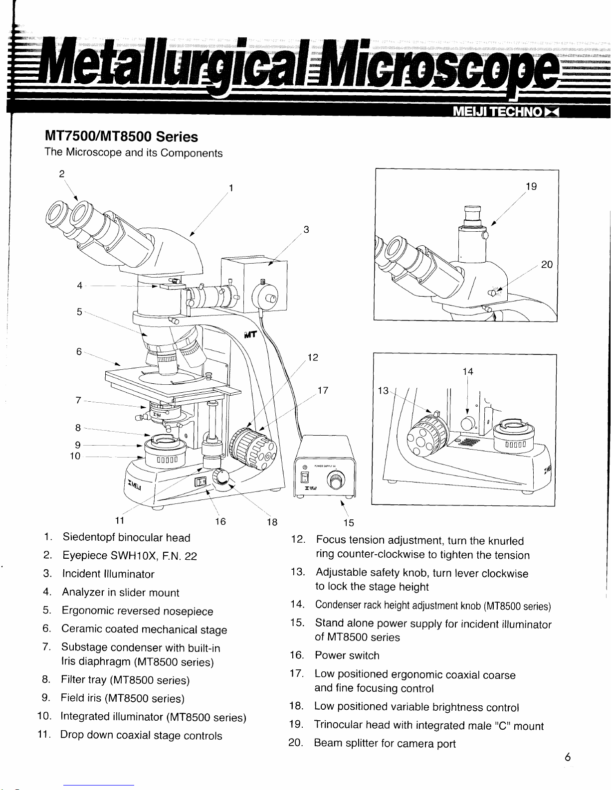
MT7500/MT8500
Series
The
Microscope
and its
Components
2
I__f,
10-
11
16
Siedentopf
binocular
head
Eyepiece
SWH10X,
F.N.
22
Incident
llluminator
Analyzer
in
slider
mount
Ergonomic
reversed
nosepiece
Ceramic
coated
mechanical
stage
Substage
condenser
with
built-in
lris
diaphragm
(MT8500
series)
Filter
tray
(MT8500
series)
Field
iris
(MT8500
series)
Integrated
illuminator
(MT8S00
series)
Drop
down
coaxial
stage
controls
1B
\
15
12.
Focus
tension
adjustment,
turn
the
knurled
ring
counter-clockwise
to tighten
the
tension
13.
Adjustable
safety
knob,
turn
lever
clockwise
to
lock
the
stage
height
14.
condenser rack
height
adjustment
knob
(MTB500
series)
15.
stand
alone
power
supply for
incident
illuminator
of MTB500
series
16.
Power
switch
17.
Low
positioned
ergonomic
coaxial
coarse
and
fine
focusing
control
18.
Low
positioned
variable
brightness
control
19.
Trinocular
head
with
integrated
male
"C" mount
20.
Beam
splitter for
camera
port
\ie
2.1
Installation Site
The microscope
should be operated
in a
room with as little dust as
praclically possible.
Keep
your
instrumenl away
from solvents,
chemical
fumes
and
excessive humidity.
Also try to avoid big
swings
in ambient
temperature, direct sunlight
and
vibration
as
they can aflect
measurements and
instrument
performance.
Operating
Ambient
Conditions
Temperature:
10
-
36'C
(50
-
96.8"F)
Relative
Humidity: 0 - 80%
up to
30'C
(86'F)
2.2 Unpacking
Please check
your
packing
slip to
insure that all materials are
present.
Keep a copy
{or
your
records so
that
you
have
the
proper
information
when ordering
more equipment, ordering
replacement
parts
or
accessories or
when
calling
for technical support.
Please
make
sure
that no small
pieces
or
parts
are
left
in
the
packing
material.
Keep the
packing
materials
in
a safe
place
for the
purpose
of storage
and
transporting the
microscope and
its
accessories.
[zi\lrrenrrou
Avoid touching
the
surface
of optical
components
such as
lenses,
filters
and
glass
surfaces.
Even
very
small
traces of
perspiration
or finger oils can
corrode the surfaces ot
optics in
a short
Deriod
of time.
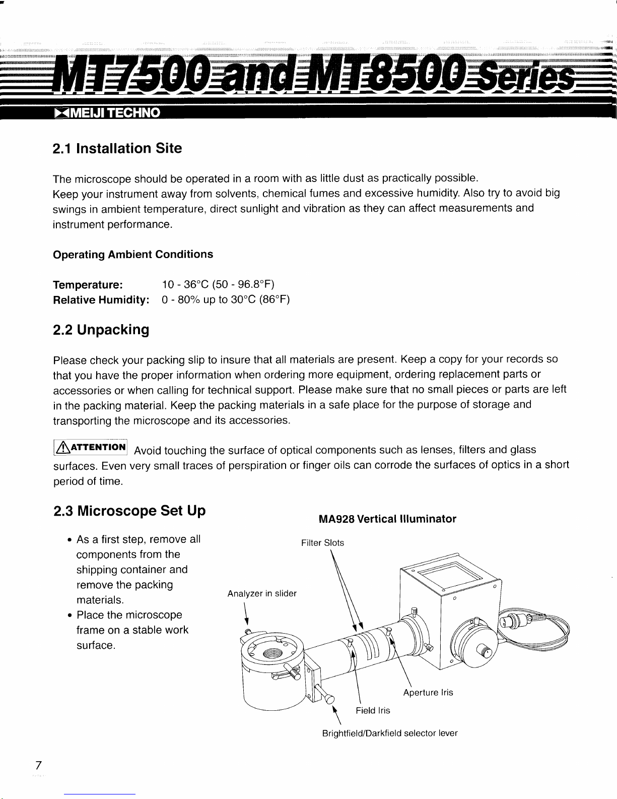
2.3
Microscope Set
Up
.
As a first
step,
remove
all
components
from the
shipping container
and
remove
the
packing
materials.
.
Place the
microscope
frame
on a
stable
work
surface.
Filter S
MA928 Vertical
llluminator
lots
\
\
\
Aperture
lris
Brightfield/Darkfield selector
lever
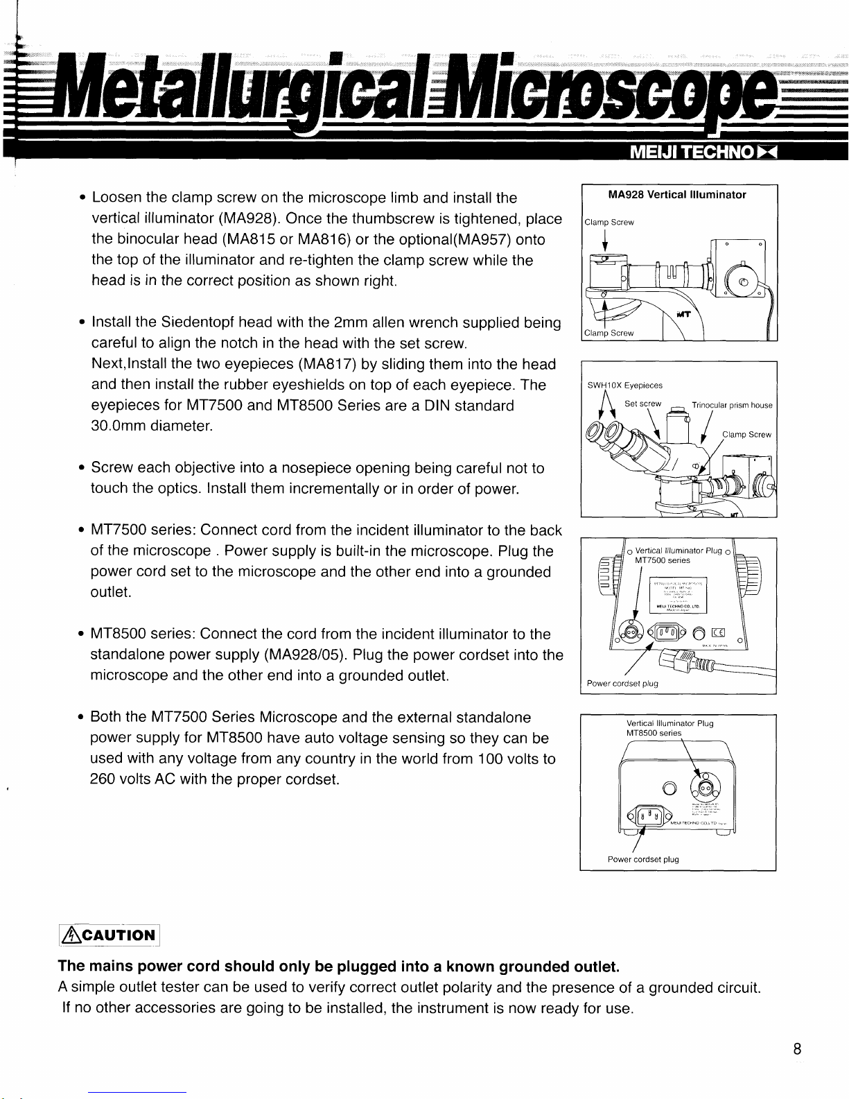
.
Loosen the
clamp screw
on the microscope limb
and
install
the
vertical illuminator
(MA928).
Once the thumbscrew is
tightened,
place
the binocular head
(MAB15
or MAB16)
or
the
optional(MAgs7) onto
the
top
of the
illuminator
and
re-tighten
the clamp
screw
while the
head is
in
the correct
position
as
shown right.
.
lnstall
the
Siedentopf head with
the Zmm
allen
wrench
supplied being
careful
to
align
the notch in
the head with
the
set screw.
Next,lnstall
the two
eyepieces
(MAB17)
by
sliding
them
into
the head
and
then install
the rubber
eyeshields on top
of each eyepiece.
The
eyepieces for MT7500
and MT8500
Series are a DIN
standard
30.0mm diameter.
.
Screw each
objective
into
a
nosepiece
opening being
careful
not to
touch the
optics.
Install
them
incrementally
or
in
order
of
power.
.
MT7500
series:
Connect cord from the incident illuminator
to the
back
of
the microscope .
Power
supply
is
built-in
the
microscope.
Plug the
power
cord
set to the
microscope
and
the
other end
into
a
grounded
outlet.
.
MT8500
series:
Connect the
cord
from
the
incident
illuminator to
the
standalone
power
supply
(MA928/05).
Plug
the
power
cordset
into
the
microscope
and the
other end
into
a
grounded
outlet.
.
Both
the MT7500
Series Microscope
and the
external
standalone
power
supply
for
MTB500
have
auto
voltage
sensing so they can
be
used
with
any
voltage from
any country in the world f rom 100 volts
to
260 volts AC with
the
proper
cordset.
Vertical
llluminator
Plug
MTB500
series
Power
cordset
plug
MA928 Vertical llluminator
Clamo Screw
SWH10X Eyepieces
A
/ t
Set sc.rew
, ,
Trinocular
prism
house
7t
r ffi /
9
Vertical llluminator Plug
9
MT7500
series
=t , tF
1l l- \F
ll ll
':
| \E
y/
/l
'^'
|
\\
ll I I
',u',,.nno.oro
| .
| |
|
"
I
I
I /'O\
I
.@-@De
re
o
LAq"rrrfgll
The mains
power
cord should only be
plugged
into a known
grounded
outlet.
A
simple outlel lester can be
used
to verify
correct outlet
polarity
and the
presence
of a
grounded
circuit.
lf no other
accessories are
going
to be installed, the instrument
is
now
ready
lor
use.
 Loading...