

Page 1
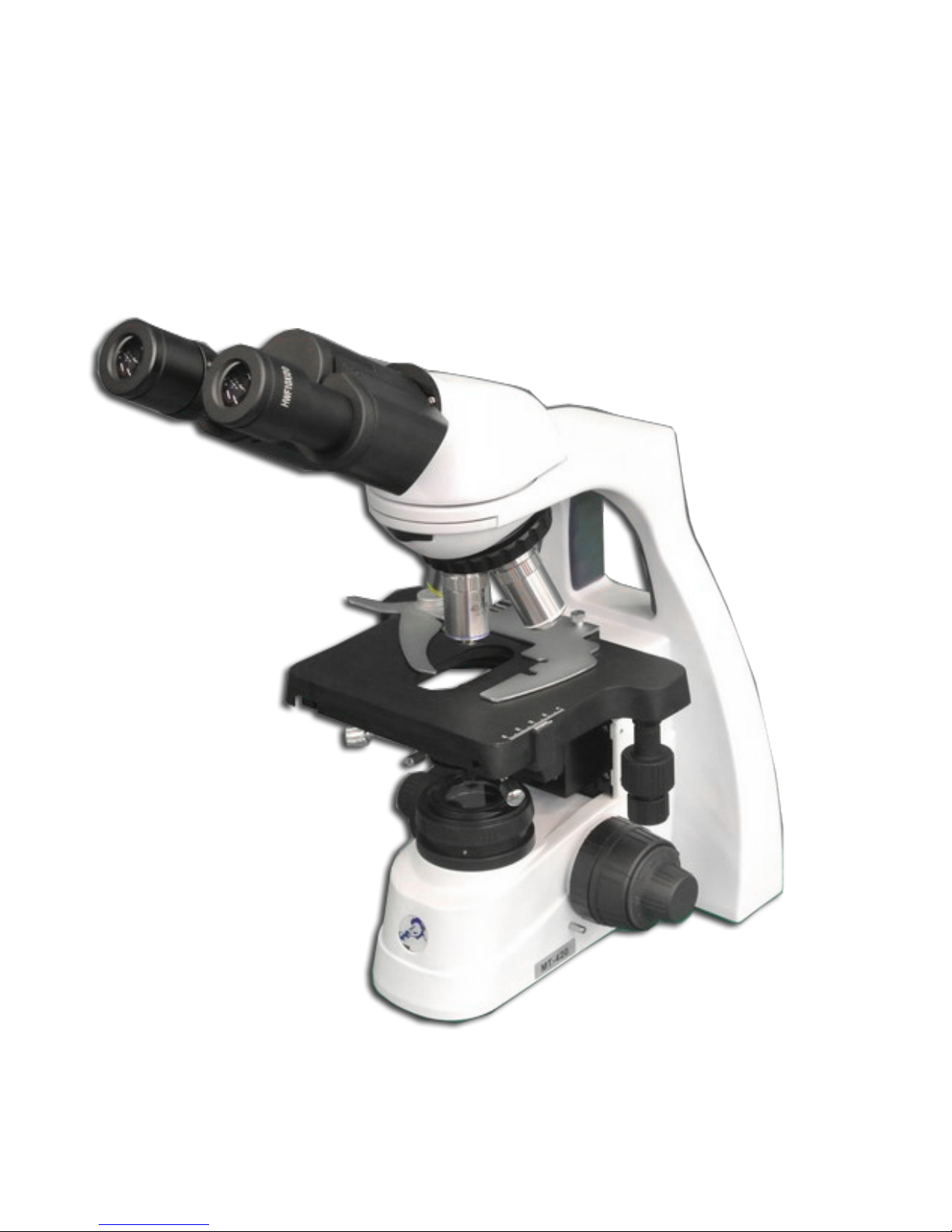
User Manual for MT - 420 and MT - 430 Series
Page 2

INTRODUCTION
Thank you for purchasing the MT - 420 and MT - 430 Series.
The MT - 420 and MT - 430 Series has been designed with all kinds of Life Sciences applications and great
durability in mind. This resulted in a modern, robust and high-level microscope for advanced use, equipped
with the best optical and mechanical components. Specic attention to production methods resulted also in
an excellent price / performance ratio.
Please read this manual carefully before using the product to ensure correct and safe usage.
• The contents of this manual are subject to change without notice.
• The appearance of the actual product can differ from the models described in this manual.
• Not all equipment mentioned in this manual has to be part of the set you have purchased.
• All optics are anti - fungus treated and anti - reection coated for maximum light throughput.
Page 3

INDEX
Notes on handling the Safety ............................................................................................................ 4
Components of the microscope ......................................................................................................... 6
Preparing the MT - 420/MT - 430 for use ............................................................................................ 7
Assembling Steps ............................................................................................................................................8
Operation ............................................................................................................................................. 9
Place the specimen slide ................................................................................................................................9
Focusing and slide protection ...................................................................................................................... 10
Adjusting the focusing tension .................................................................................................................... 10
1. The interpupillary distance ...................................................................................................................... 11
2. The correct eye point ............................................................................................................................... 11
3. Adjusting the diopter ................................................................................................................................ 12
Abbe condenser ............................................................................................................................................ 12
The eld (Köhler) diaphragm ....................................................................................................................... 12
Adjusting the Aperture Diaphragm .............................................................................................................. 12
Use of the S100x oil-immersion objective .................................................................................................. 13
Illumination MT - 420 and MT - 430 Series ................................................................................................... 13
Phase contrast .................................................................................................................................. 14
Using the Zernike phase contrast set ......................................................................................................... 14
Aligning the phase rings ............................................................................................................................... 15
Using the Phase Contrast Slider condenser (optional) .............................................................................. 16
Maintenance and cleaning .............................................................................................................. 17
Cleaning the optics ........................................................................................................................................17
Caution ...........................................................................................................................................................17
Maintenance of the stand .............................................................................................................................17
Replacing the fuse ........................................................................................................................................ 18
Replacing/ placing the rechargeable batteries (optional) ......................................................................... 18
Using the Kensington Security Slot ............................................................................................................. 19
Digital cameras ................................................................................................................................. 20
Page 4

NOTES ON HANDLING AND SAFETY
Handle with care
• This product is high quality optical instrument. Delicate handling is required.
• Avoid subjecting it to sudden shocks and impact.
• Impacts, even small ones, can affect the precision of the objective.
Handling the LED
Note: Always disconnect the power cord from your microscope before handling the LED bulb and
power unit and allow the system approximately 35 minutes to cool down to avoid burns.
• Never touch the LED with your bare hands.
• Dirt or ngerprints will reduce the life time and can result in uneven illumination lowering
the optical performance.
• Use only original replacement LEDs.
• Use of other products will cause malfunctions and void warranty.
• During use of the microscope, the power unit will get hot, never touch it while in opera-
tion and allow the system approximately 35 minutes to cool down to avoid burns.
Dirt on the lenses
• Dirt on or inside the optical components such as eyepieces, lenses, etc., affect the
image quality of your system negatively.
• Always try to prevent your microscope from getting dirty by using the dust cover, prevent
leaving ngerprints on the lenses and clean the outer surface of the lens regularly.
• Cleaning optical components is a delicate matter. Please read the cleaning instructions
on our website carefully.
Environment, storage and use
• This product is a precision instrument and it should be used in a proper environment
for optimal use.
• Install your product indoors on a stable, vibration free and level surface.
• Do not place the product in direct sunlight.
• The ambient temperature should be between 5 to +40ºC and humidity is maximum
80% at 31 degrees decreasing linearly to 50% at 40 degrees. Although the system is
anti - mold treated, installing this product in a hot, humid location may still result in
the formation of mold or condensation on lenses, impairing performance or
causing malfunctions.
• Never turn the right and left focus knobs in opposite directions at the same time or turn
the coarse focus knob past its farthest point, this will damage this product.
• Never use undue force when turning the knobs.
Page 5

Environment, storage and use (continued)
• Make sure that the microscope system can dissipate its heat.
• Keep the microscope approximately 15cm free from walls and obstructions.
• Never turn the microscope on when the dust cover is in place or when items are placed
on the microscope.
• Keep ammable uids, fabric etc. well out of the way.
Disconnect power
• Always disconnect your microscope from power before doing any maintenance, cleaning,
assembling or replacing LEDs to prevent electric shocks.
Prevent contact with water and other uids
• Never allow water or other uids to come in contact your microscope, this can cause
short circuiting your device, causing malfunction and damage on your system.
Moving and assembling
• The MT - 420 and MT - 430 microscopes are relatively heavy systems, consider this when
moving and installing the system.
• Always lift the microscope by holding the main body and base of the microscope.
• Never lift or move the microscope by its focusing knobs, stage or head.
• When needed, move the microscope with two persons instead of one.
Page 6
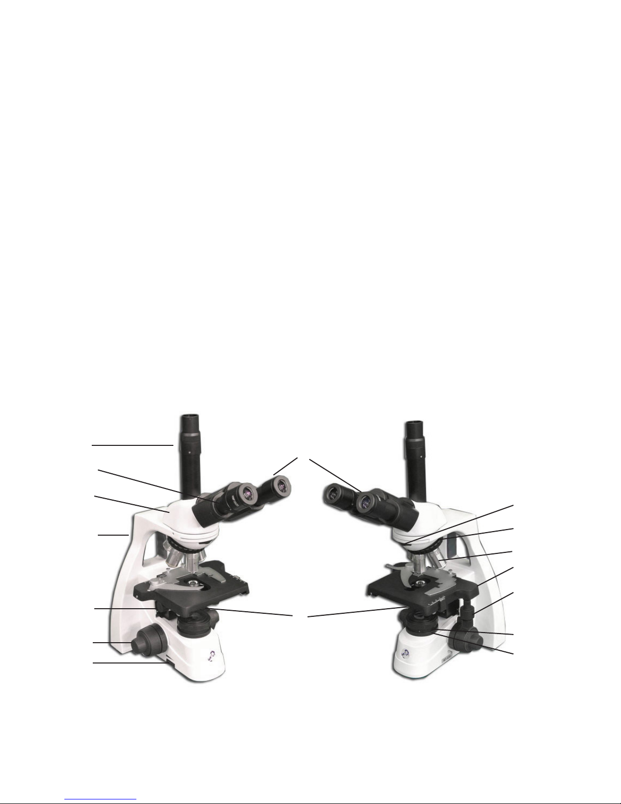
COMPONENTS OF THE MICROSCOPE
The names of the components are listed below and are indicated in the picture
A Microscope head J Collector lens
B Eyepieces K Trinocular tube
C Diopter adjustment L Light intensity adjustment knob
D Nosepiece M Coaxial coarse adjustment
E Objectives N Slide protection handle
F Stage with X-Y mechanical stage O Condenser height control
G X-Y stage controls P Slide for polarization lter
H Condenser with iris diaphragm Q Transport handle
I Köhler iris diaphragm
K
C
A
Q
O
M
L
B
P
D
E
F
G
H
I
J
Page 7
PREPARING THE MT-420/MT-430 FOR USE
Carefully remove the items from its packaging and place them on a at, rm surface. Please do
not expose the microscope to direct sun light, high temperatures, damp, dust or acute shake.
Make sure the table or surface is at and horizontal.
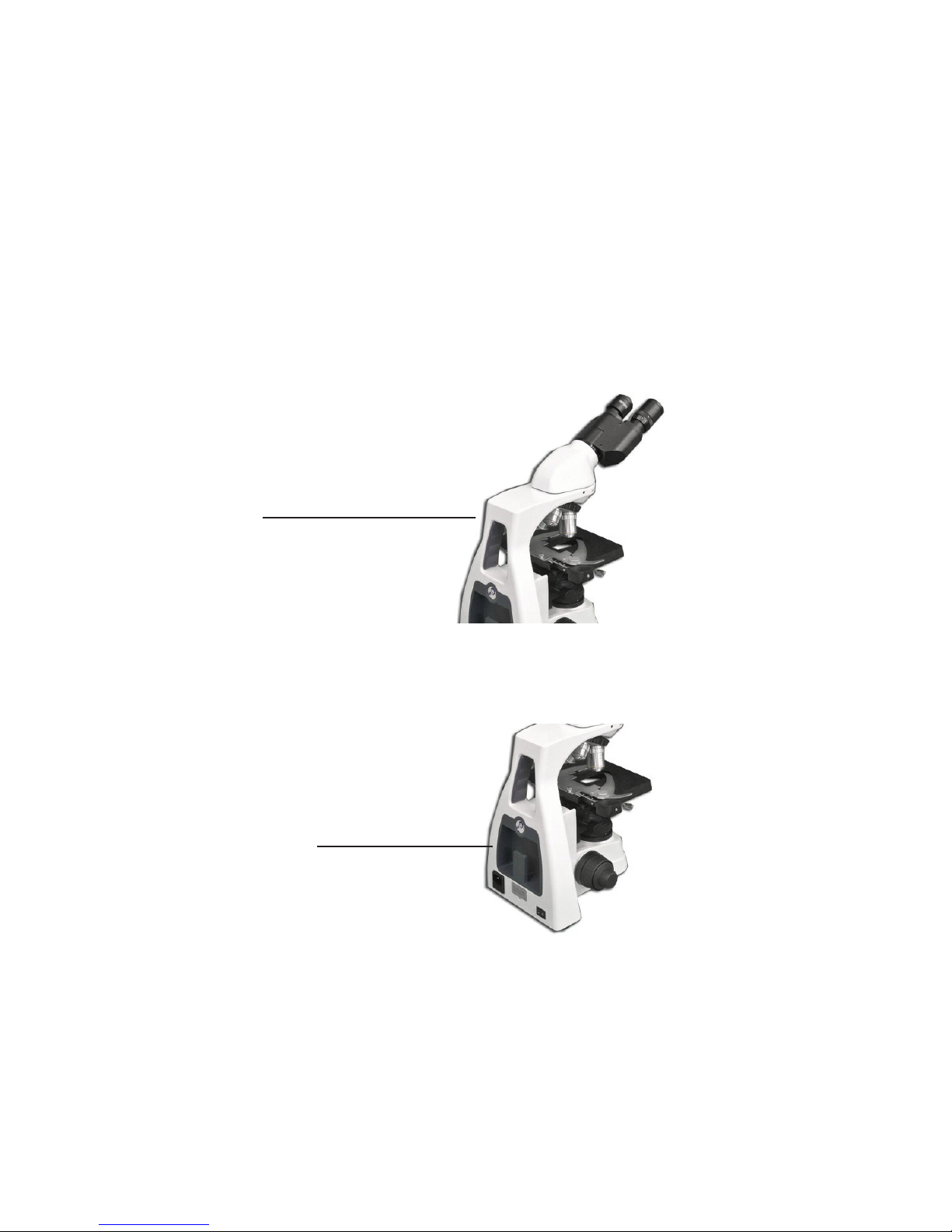
When moving the microscope, use the left hand to hold the transport handle and with hold the
base of the microscope with the right hand.
Transport handle
CAUTION! Holding the microscope by its stage or focusing knob will damage the microscope.
Insert the power cord into the back of the microscope and use the cable storage system CSS - Cable Storage System — to store the cable after use.
CSS - Cable Storage System
CAUTION! If the bacterial solution or water splatters over the stage, objective or head, pull out the
power cord immediately and dry the microscope.
For safety reasons, make sure the power switch is turned off and the plug is removed before
replacing the led unit or fuse.
Page 8

ASSEMBLING STEPS
We always try to keep the number of assembly steps for their customers as low as possible but
in some cases there are some steps to be taken. The steps mentioned below are often not
necessary but described for your convenience nonetheless.
Mounting the objectives
1. Rotate the coarse focusing knob to lower the stage to its lowest position.
2. Install the objectives into the objective nosepiece from the lowest magnication to the highest
in a clockwise direction from the rear side of the microscope. When using the microscope, start
using the low magnication objective (4X to 10X) to search for specimen and focus, and then continue with high magnication objective to observe.
The microscope head
The standard MT - 420 and MT - 430 series conguration are supplied with the head assembled.
However, if your order contains a uorescence or metallurgical attachment then this should be
mounted rst. There is a supplementary manual supplied with any intermediate attachment with
detailed mounting instructions.
Placing the eyepieces
1. Remove the cover of eyepiece tube.
2. Insert the eyepiece into the eyepiece tube.
3. Lock the eyepieces with a hexagon screw.
The eyeshades (optional)
The eyepieces can be equipped with optional rubber eyeshades. This prevents damage to the lens
and stray light. The eyeshade can simply be slipped over the eyepiece.
Connecting the power cord
The MT - 420 and MT - 430 Series microscopes supported a wide range of operating voltages: from
100 to 240V. Please use a grounded power connection.
1. Make sure the power switch is off before connecting.
2. Insert the connector of power cord into the microscope’s power socket and make
sure it connects well.
3. Insert the other connector into the main socket and make sure it connects well.
Do not bend or twist the power cord, it will get damaged. Use the power cord that is supplied.
If it is lost or damaged, choose one with the same specications.
Page 9

OPERATION
Setting up the illumination
For optimal contrast and resolution one should follow the below procedure:
• Place a specimen on the object stage and focus using the 4X objective with a fully
opened iris diaphragm.
• Turn light intensity to lowest position, then look through the eyepiece(s) and turn up to
the comfortable light intensity level.
• Turn the condenser in the highest position (for phase contrast models, please set
condenser to bright eld position).
• Close the iris diaphragm, until it is just visible on the edge of the eld of view.
The microscope is properly set for use with the 4X objective. For each other magnication in bright
eld use this procedure should be repeated to ensure the best balance between contrast and
resolution. Phase contrast set up is explained later in this manual.
Place the specimen slide
1. Push the arm of the specimen holder backwards.
2. Release the arm slowly clamping the slide with the cover glass facing up.
3. Rotating the X and Y - axis knob will move the specimen to the center of alignment with
the center of the objective.
Page 10
Focusing and slide protection
1. Select the 4X objective and make sure that it is placed correctly in the optical path.
2. Rotate the position screw to top, observe the right eyepiece with your right eye. Rotate
the coarse focusing knob until the image appears.
3. Rotate the ne focusing knob to sharpen the image.
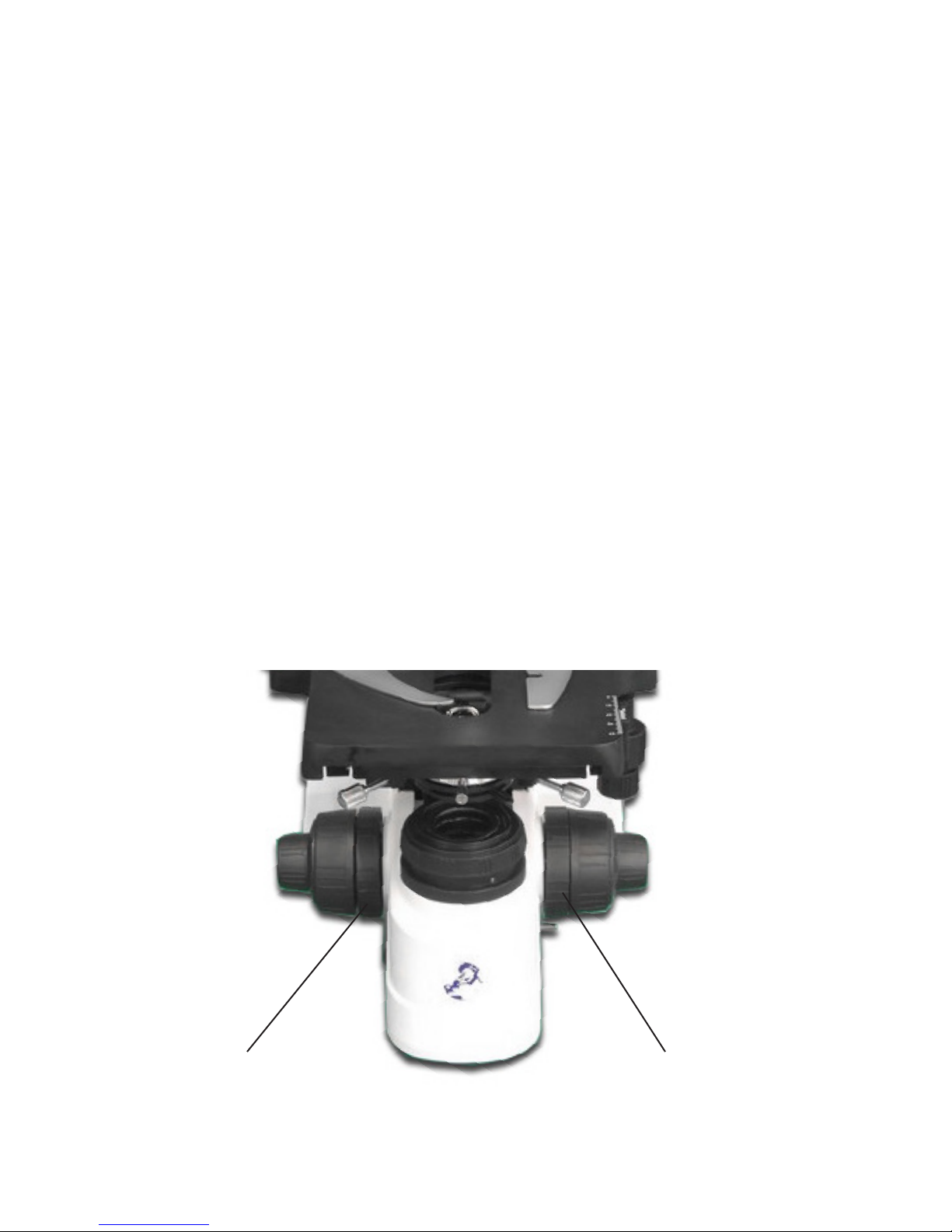
4. When you perform focusing with a S100X objective, you need to lock the slide protection
handle. The slide protection handle protects the slide by limiting the travel range of the
mechanical stage. This way the objectives will not touch or break your slides:
Adjusting the focusing tension
The tension of the focusing knobs can be adjusted. You can set it from light to heavy according to
your own preference. Please note that when the specimen leaves the focus plane after focusing or
the stage declines out of its own, then you need to adjust the tension.
To tighten the focusing knob (move heavy), rotate the tension adjustment ring counter-clockwise;
to loosen it, please turn it in the clockwise direction.
Slide protectionFocusing tension
Page 11
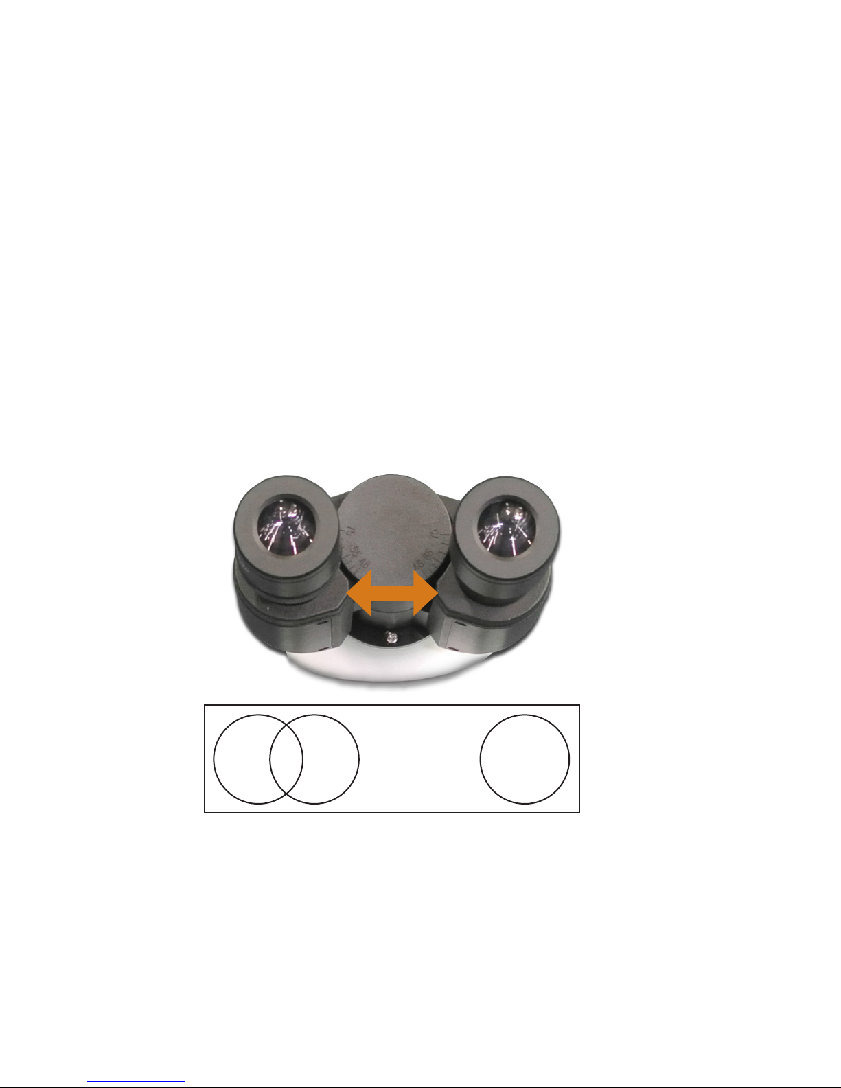
Eyepieces
Using a binocular (or trinocular) tube is less tiring for the eyes than a monocular tube. In order to
obtain a smooth “compound” image, we recommend you to go through the below steps.
1. The interpupillary distance
The correct interpupillary distance is reached when one round image is seen in the eld of view
(see image below). This distance can be set either pulling the tubes towards each other or pulling
them away from each other. This distance is different for each observer and thus should be set
individually. When more users are working with the microscope it is recommended to remember
your interpupillary distance for a quick set up during new microscopy sessions. The MT - 420 and
MT - 430 swiveling eyepiece tube can be rotated 360º. You can select corresponding eye point
height according to your own preference.
Field of view before
adjustment
2. The correct eye point
The eye point is the distance from the eyepiece to the user’s pupil. To obtain the correct eye point,
move the eyes towards the eyepieces until a sharp image is reached at a full eld view.
Field of view after
adjustment
Page 12

3. Adjusting the diopter
• Set diopter adjustment ring to zero.
• Close the left eye and focus the right tube by adjusting the coarse and ne adjustment knobs.
• Close the right eye and focus the left tube with the diopter adjustment ring.
This procedure should be followed by each individual user. When more users are working on the
same microscope it is recommended to remember your own diopter setting for a quick set up
during new microscopy sessions.
Abbe condenser
Beneath the object stage an Abbe condenser N.A. 12.5 is mounted. The condenser can be
adjusted in height by moving the rack and pinion knob beneath the mechanical stage. By adjusting
the condenser you can focus the light on the specimen for a optimized contrast. The condenser is
factory pre-centered. If needed, the following procedure can be followed to the center the condenser.
1. Move the condenser to its highest position.
2. Select the 10X objective and place it into the light path and focus the specimen.
3. Rotate the eld diaphragm adjustment ring to put the eld diaphragm to the
smallest position.
4. Adjust the condenser to the point where the image is the sharpest.
5. Adjusting the center adjustment screw and put the image to the center of the eld of view
6. Open the eld diaphragm gradually.
7. The condenser is centered correctly if the image remains in the center when you open
the eld diaphragm and inscribed to the eld of view.
The eld (Köhler) diaphragm
By limiting the diameter of the beam entering the condenser, the eld diaphragm can prevent other light
and increase the image contrast. When the image is just on the edge of the eld of view, the objective
can show the best performance and obtain the clearest image. The diaphragm is factory pre-centered.
Adjusting the Aperture Diaphragm
1. The aperture diaphragm is used to select the numerical aperture of the illumination.
When the N.A. of the illumination matches the N.A. of the objective, you get the highest
possible resolution, depth of eld and contrast.
2. When contrast is low, rotate the diaphragm adjustment ring to 70%–80% of the N.A. of
objective this will improve the contrast of the image. The diaphragm is factory pre-centered.
Page 13

Use of the S100x oil-immersion objective
The MT - 420 and MT - 430 microscopes are equipped with an S100X N.A. 1.25 oil immersion
objective. Please follow the below instructions on how to use this objective:
1. Remove the dust protection cap from the revolving nosepiece to mount the S100X objective.
2. Focus the image with the S40X objective.
3. Lock the slide protection handle.
4. Turn the revolving nosepiece so the S100X objective almost reaches the click-stop.
5. Put a small drop of immersion oil on the center of the slide (always use Immersion oil).
6. Now turn the S100X objective so that you feel the click stop.
7. The front lens is in contact with the immersion oil.
8. Look through the eyepiece and focus the image with the ne adjustment knobs.
9. The distance between the lens of the objective and the slide is very small!
10. In case there are small bubbles visible, turn the S100X objective a couple of times from
left to right so that the front of the objective moves in the oil and the bubbles will disappear.
11. After using the S100X objective, loosen the slide protection handle and turn the table
with the course adjustment knobs downwards until the front lens doesn’t touch the oil
any longer. Clean the front lens of the S100X objective.
12. Always clean the front lens of the S100X objective with a piece of lens paper that is
moistened with a drop of isopropanol. We recommend using lens paper and isopropanol.
13. Clean the slide after use as well.
Illumination MT-420 and MT-430 Series
The illumination has the following specications:
• LED: 3W NeoLED for binocular and trinocular models
• Power supply: Primary AC 100 – 240 Volt-50Hz.
Page 14
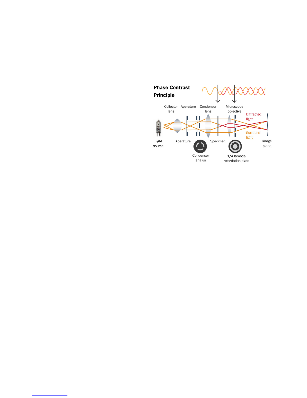
PHASE CONTRAST (OPTIONAL)
Use of phase contrast with the MT-420 and
MT-430 microscope
The phase contrast method was designed
in 1934 by the Dutchman Frits Zernike to
observe very thin or transparent objects. This
technique uses the fact that light traveling
through tissue undergoes a phase shift due
to diffraction.
By recombining the phase shifted light with
the background light, a contrasted image
appears in the eyepiece.
Using the Zernike phase contrast set
Any MT-420 and MT-430 model with a Zernike phase contrast set comes with the phase
contrast condenser and objectives already mounted and centered on your microscope. If you
suspect misalignment or want to check the alignment please see the next point for “centering the
phase rings”.
The height of condenser can be adjusted by turning the rack and pinion up and down. By doing
this the light beam will be focused more on the specimen for maximum resolution.
The Zernike phase disc has ve positions:
“0” for bright eld observation, this position also has an iris diaphragm.
“10”
“20”
“40”
“100”
These positions correspond to the respective phase contrast objectives 10X, 20X, 40X an 100X.
When the condenser is in the “0” position, the objectives can be used for bright eld observation.
For phase contrast, the condenser position should match the objective used. Meaning that when
the condenser is in position “40” the objective used should also be 40X.
Page 15
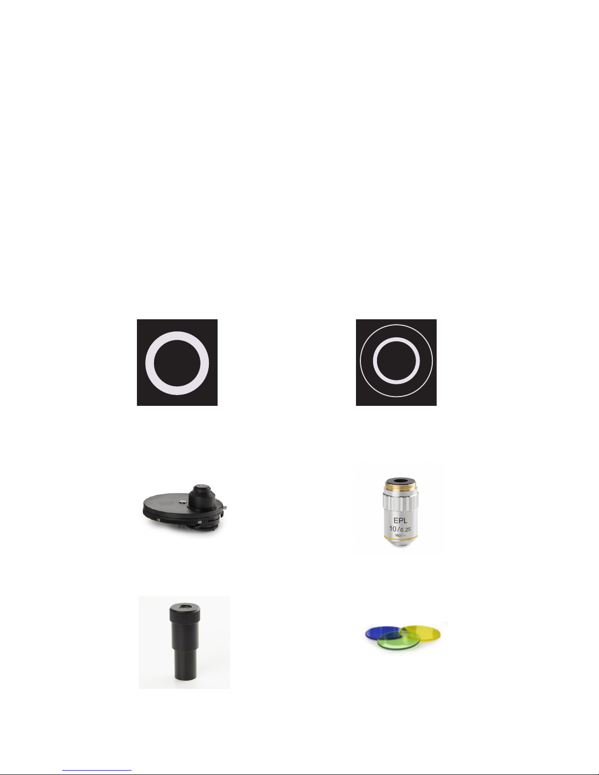
Aligning the phase rings
To center:
Rotate 10X innity plan phase contrast objective into the eld of view, then set the Zernike phase
disc to position “10” to match the objective.
Take the eyepiece out of the tube and insert centering telescope in its place. When looking through
the centering telescope, the dark and bright ring images should coincide with each other as shown
in the gures below. If the ring images can’t be observed clearly, focus the centering telescope rst
and if this does not solve the issue then try to adjust the condenser by turning it up and down.
If the bright ring and dark ring images are not coincided as shown below, adjust the position of the
ring by moving the ring at the bottom side of the condenser with your ngers. Move it until bright
and dark ring images superimposed. Repeat for all objectives/ Zernike disk positions.
Not centered
Phase condenser
Centering telescope
Centered properly
Phase objective
Filters
Page 16

USING THE PHASE CONTRAST SLIDER CONDENSER
(OPTIONAL)
1. Keep the phase contrast slider face up (text up); insert it from left to right into the
condenser slider socket as the direction of the arrow pointed.
2. Each slider has 3 positions, 2 phase contrast positions and in the center of the slide the
bright eld position for normal use without phase contrast. Each phase contrast
objective used, has to match with the phase contrast ring on the slider. For example:
when the 10X phase contrast objective is used, the slider should be positioned to match
the 10 phase diaphragm.
Note: The phase diaphragms in the sliders are pre-centered. It is not needed to adjust it before using.
Page 17

MAINTENANCE AND CLEANING
Always place the dust cover over your MT-420/MT-430 microscope after use. Always keep the
eyepiece and objectives mounted on the microscope to avoid dust entering the instrument.
Cleaning the optics
When the eyepiece lens or front lens of the 10X or S40X objective are dirty, they can be cleaned by
wiping a piece of lens paper over the surface (circular movements). When this does not help put a
drop of alcohol on the lens paper and wipe it. Never put xylol or alcohol directly on the lens! Please
note that offers a special microscope cleaning kit: PB.5275
It is not necessary — and not recommended — to clean the lens surfaces at the inner side of the
objectives. Sometimes dust can be removed with high pressured air. There will never be dust in the
objectives if the objectives are not removed from the revolving nosepiece.
Caution
Cleaning cloths containing plastic bers can damage the coating of the lenses!
Maintenance of the stand
Dust can be removed with a brush. In case the stand or table is really dirty then you can clean the
surface with a non-aggressive cleaning product.
All moving parts like the height adjustment or the coaxial course and ne adjustment contain ball
bearings that are not dust sensitive. With a drop of sewing-machine oil you can lubricate the bear-
ing.
STOP
Page 18
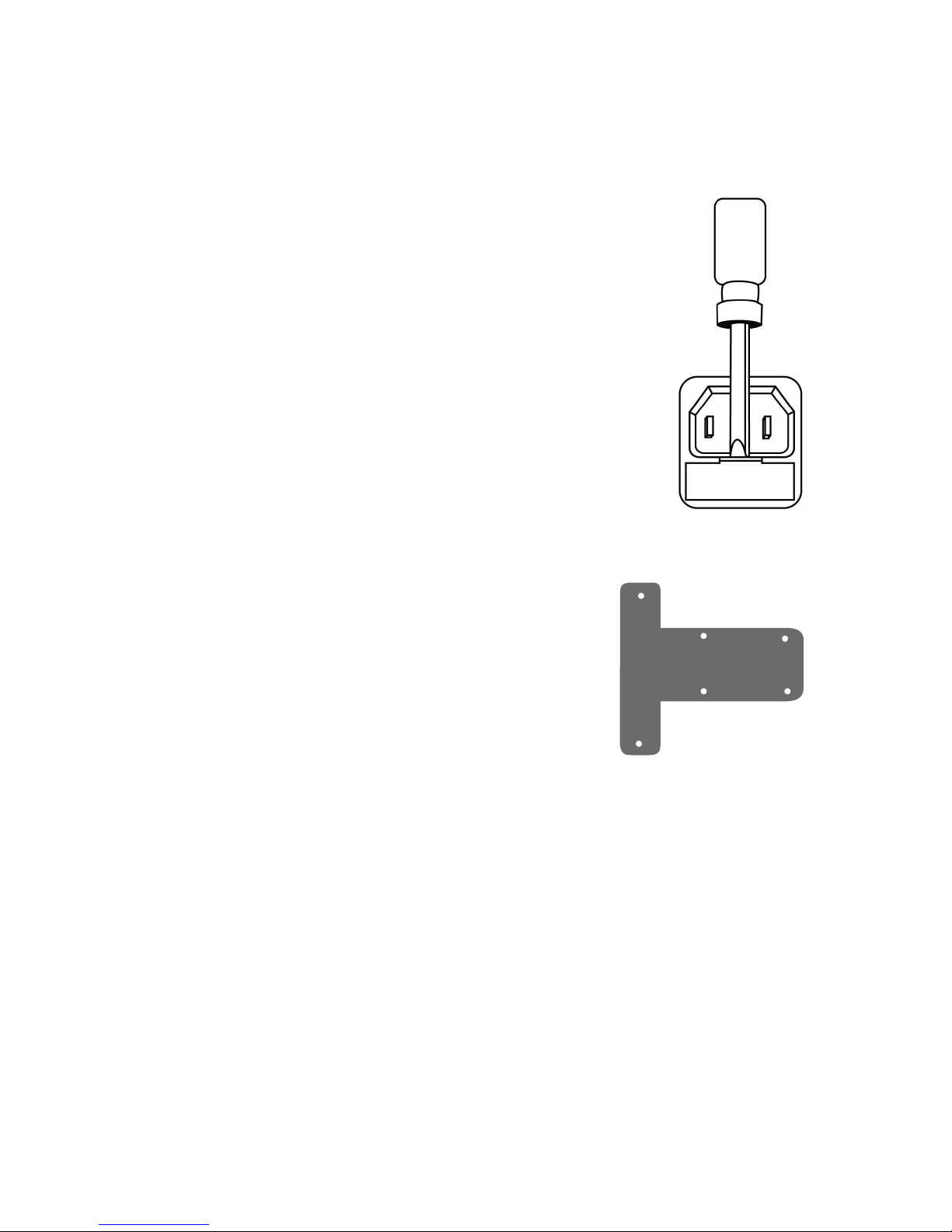
Replacing the fuse
To change the fuse, please follow these procedures:
1. Remove the power cord from the back of the microscope.
2. Locate the fuse compartment, which has a Fuse image. It is
typically located beneath the power connector.
3. Remove the fuse compartment. To do so, insert a at head screw
driver between the metal power tines and gently pry the fuse
compartment loose with a slight down and out motion.
4. Insert the new fuse into the compartment, and replace the fuse
compartment back to where it was originally.
5. Power up the microscope and test.
Note: Fuse may blow. In most cases, replacing the fuse with the correct voltage will resolve
the issue. However, should you encounter a blown fuse frequently, please contact your
distributor for further assistance.
Fuse specication: 250V, 150 mA
Replacing/placing the rechargeable batteries (optional)
1. Remove the power cord from the back of the microscope.
2. Place the microscope on its back.
3. Remove the six screws of the base of the microscope.
Location of screws are indicated on drawing aside.
4. The battery compartment in located on the baseplate.
5. Open battery compartment, by removing the small screw
on top, slide compartment open.
6. Place batteries and close the compartment.
Note: Always use high quality rechargeable batteries, preferable supplied by us. Minimum 1800mA
capacity type. Charge batteries full for 8 hours. Use microscope till batteries are fully depleted
then recharge again. Average use with full batteries 8-32 hours depending on light intensity and
battery capacity and quality.
Green battery indicator: batteries are charged
Red battery indicator: batteries are being charged
Page 19
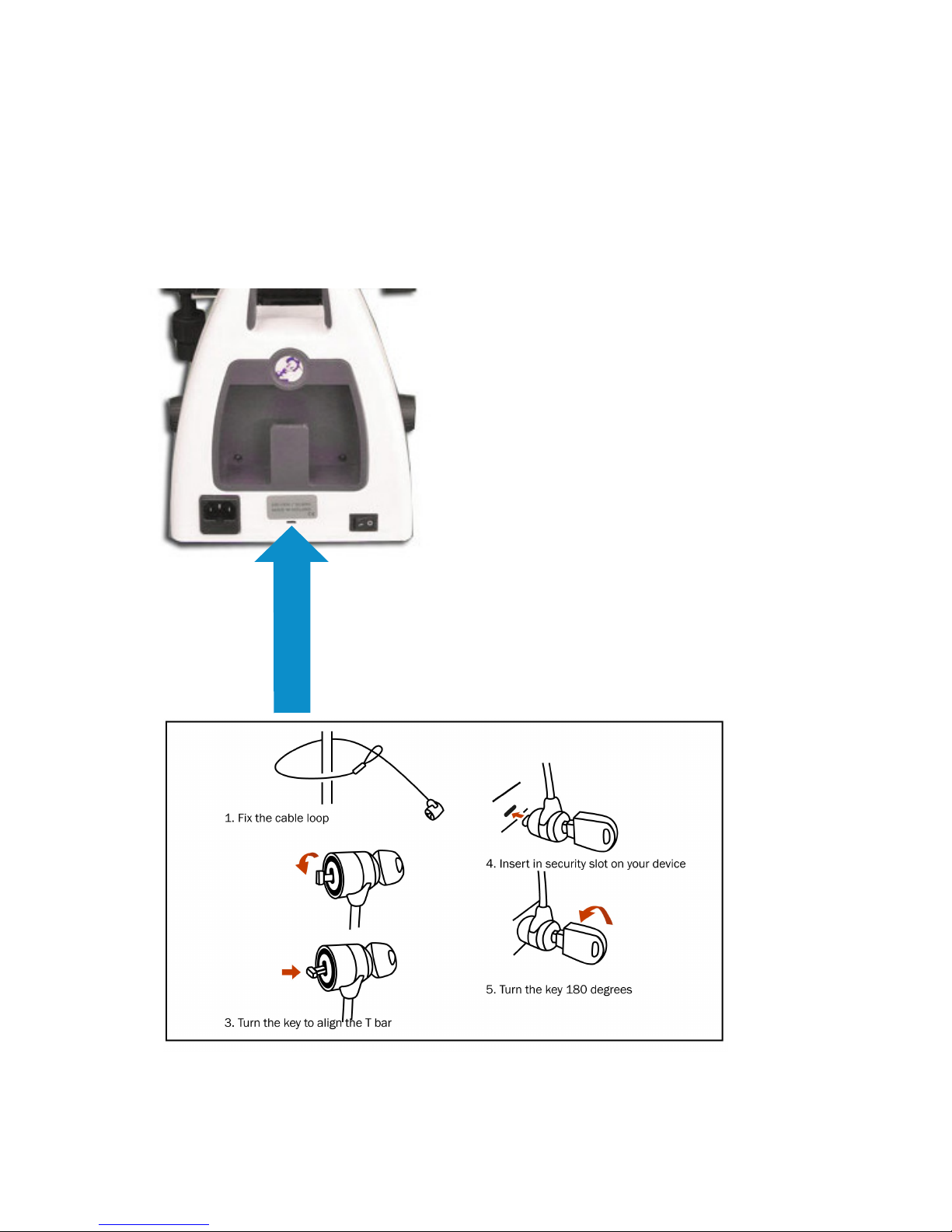
Using the Kensington Security Slot
At the back of the microscope a Kensington Security Slot is placed, which can be used to secure
the instrument from theft using a Kensington lock (not supplied)
Page 20
DIGITAL CAMERAS
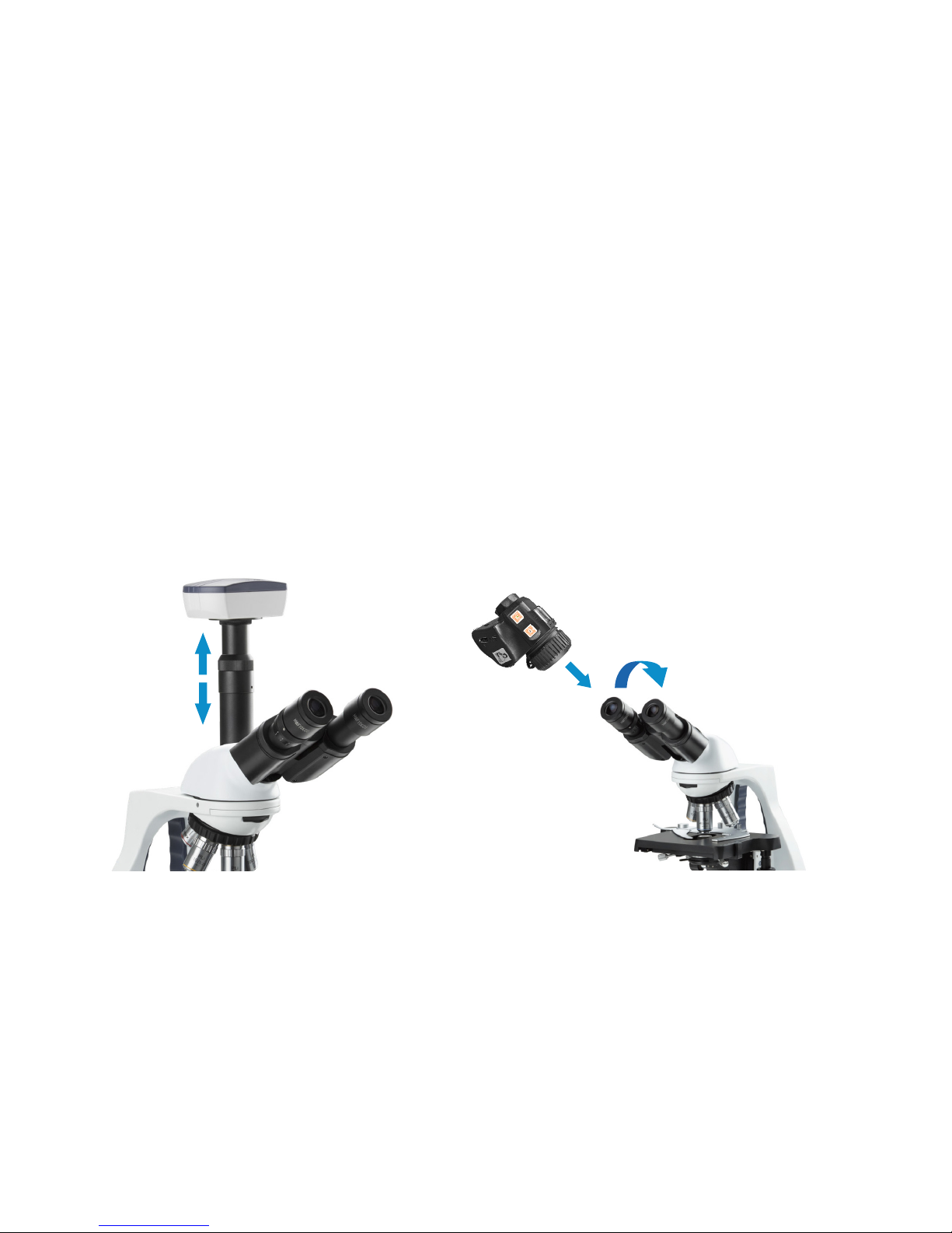
Digital cameras are designed to be used on the photo port of the microscope head. It is also
possible to use the digital camera in combination with a binocular head. To use the camera on a
binocular MT-420, you can simply remove the eyepiece[1] and then place the camera with mount-
ed c-mount adapter into the eyepiece tube[2]. Focus the digital image with the coarse and ne
controls of the microscope.
For trinocular models, slide the camera with mounted c-mount adapter into the 23.2mm tube of
the photo port. Take an easy-to-view specimen and focus the image through the microscope’s
eyepieces. For focusing the camera, slowly move tube (A) up and down while watching at the
screen till the camera view is in focus.
Follow the manual that comes with the camera for camera operation.
2
A
1
Trinocular MT-430 head with camera in photo port Binocular MT-420 innity type head with camera replacing the original eyepiece
 Loading...