

Page 1
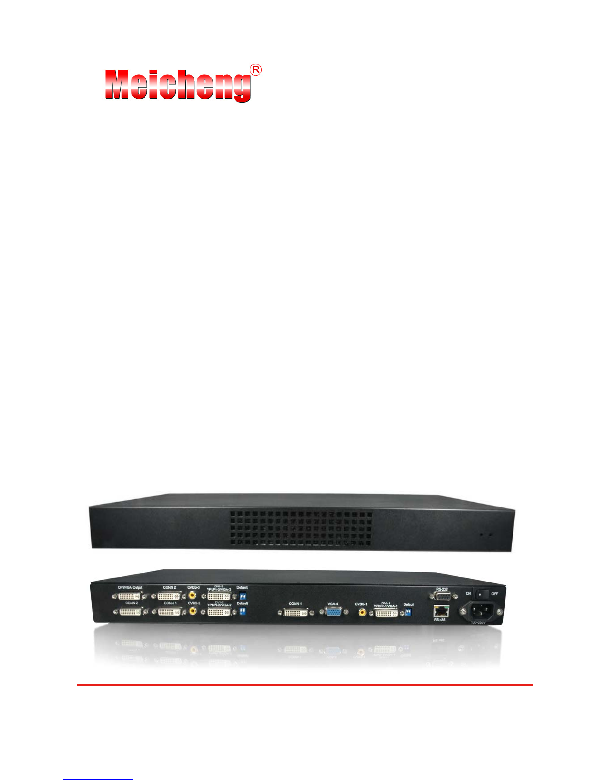
MX-1004
Quasi Quad-View Video Processor
User Manual
http://ww.meicheng.com.tw
Page 1 of 18
Page 2

Safety and Notice
The MX-1004 Quasi Quad-View Video Processor has been tested for conformity to safety
regulations and requirements, and has been certified for international use. However, like all electronic
equipments, the
MX-1004 should be used with care. Please read and follow the safety instructions to
protect yourself from possible injury and to minimize the risk of damage to the unit.
z Follow all instructions and warnings marked on this unit.
z Do not attempt to service this unit yourself, except where explained in this manual.
z Provide proper ventilation and air circulation and do not use near water.
z Keep objects that might damage the device and assure that the placement of this unit is on a
stable surface.
z Use only the power adapter and power cords and connection cables designed for this unit.
z Do not use liquid or aerosol cleaners to clean this unit. Always unplug the power to the device
before cleaning.
Page 2 of 18
Page 3

Chapter 1 Introduction 1
General 1
Features 2
Specifications 3
Package Contents 4
Inputs and Outputs 5
Chapter 2 Hardware Installation 6
Safety Precautions 6
Installation Procedure 6
Chapter 3 Operation Software 8
System Requirement and Precautions 8
Instruction of Software Connection 8
Definitions of Menu Buttons and Icons 9
Chapter 4 Tr oubleshooting 12
Warranty 13
Appendix Supported Resolution 14
Table of Contents
Page 3 of 18
Page 4
General
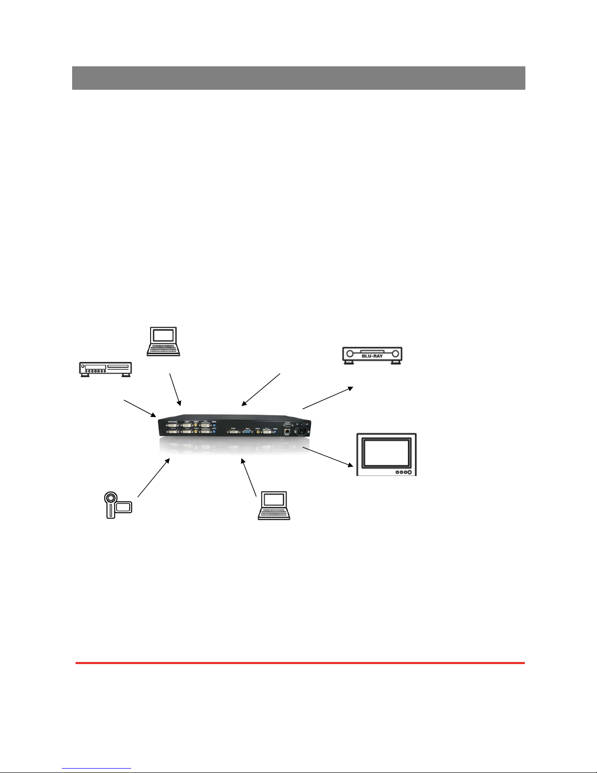
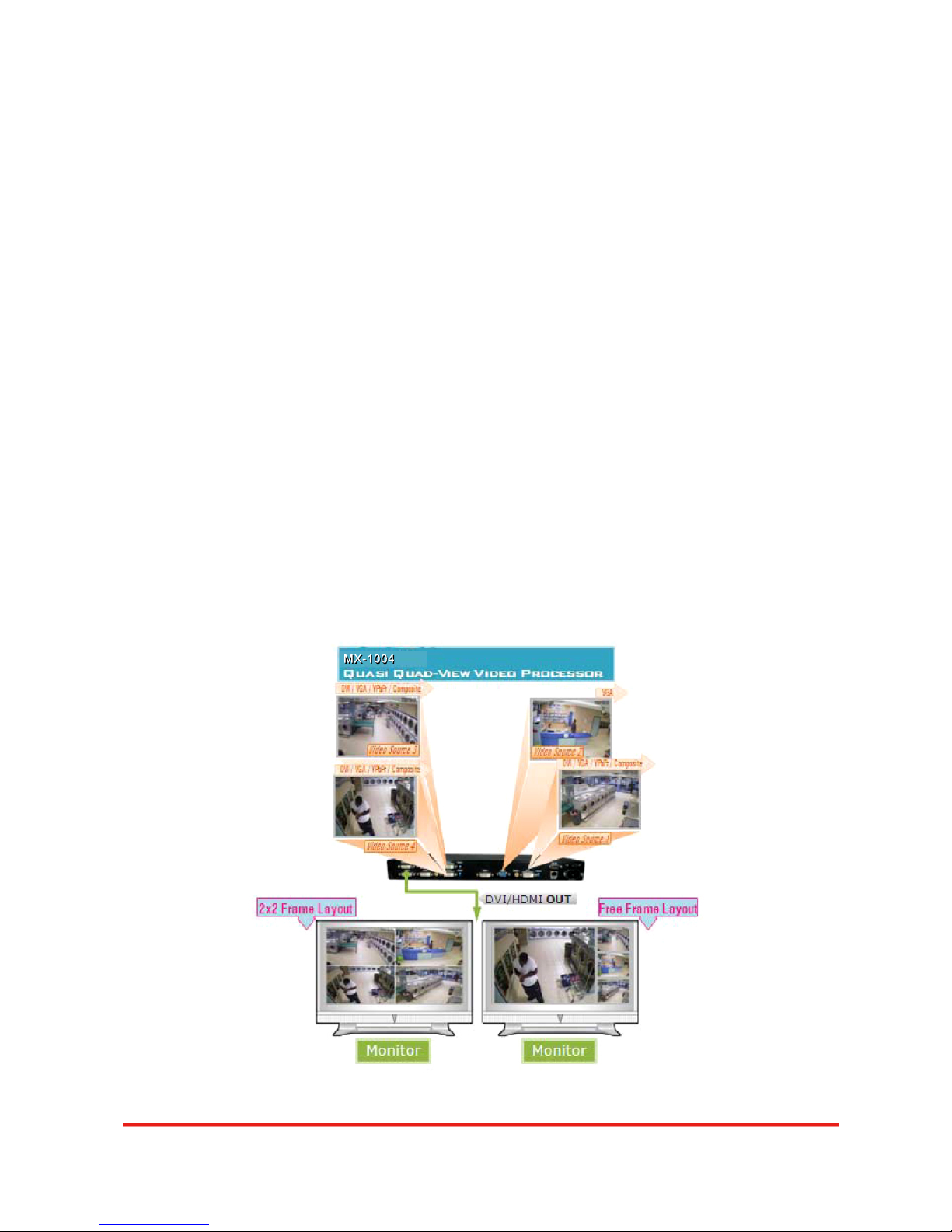
The MX-1004 Quasi Quad-View Video Processor is an advanced video processor for
multimedia presentations. It is an ideal solution for applications where up to four video signals must be
displayed on a single display. It supports up to 10 video inputs, of which four can be outputted
simultaneously with the desired display layout through software control. The advanced video
processor allows you to manipulate output images, wherever positions and whatever sizes you want
for viewing two computers or two video signals or a combination.
The embedded scaler converts signals from input sources to match the native resolution of
monitors, flat panel displays, projectors as well as user-selectable output settings up to WUXGA
(1920x1200). Dual outputs are provided in both analog (VGA) and digital (DVI) format, one is
connected to remote display and the other is connected to on-site display for real time monitoring.
Figure 1: Configuration Diagram
Introduction
DVI
VGA
DVI/VGA monitor
Remote DVI projector
Software control
Component video
Composite
Page 4 of 1
Page 5
MX -1 00 4
Features
z Four VGA, three DVI, three component and three composite inputs, from 640x480 to 1920x1200,
interlaced or progressive.
z Dual outputs (DVI / VGA), 640x480 to 1920x1200.
z Adjustable size& position through software.
z Titles, borders and colored backgrounds.
z Resize, position, flip, zoom& pan and blend output video.
z Can be cascaded to obtain more images.
z Image parameters and layouts are automatically saved in flash memory and can be recalled for
later use.
z Several Image parameters and layouts can be saved in computers and can be loaded for later
use.
z Video parameters adjustable (brightness, contrast, color temperature, etc.).
z User-selectable output settings, up to 1920x1200.
z Perfectly as a video screen splitter, a video converter and a video switcher.
z Firmware upgradable for support of new features and technology enhancements.
z Software control through RS-232/RS-485 over Cat-5.
z 1U size.
z Automatically power-saving mode.
Page 5 of 18
Page 6
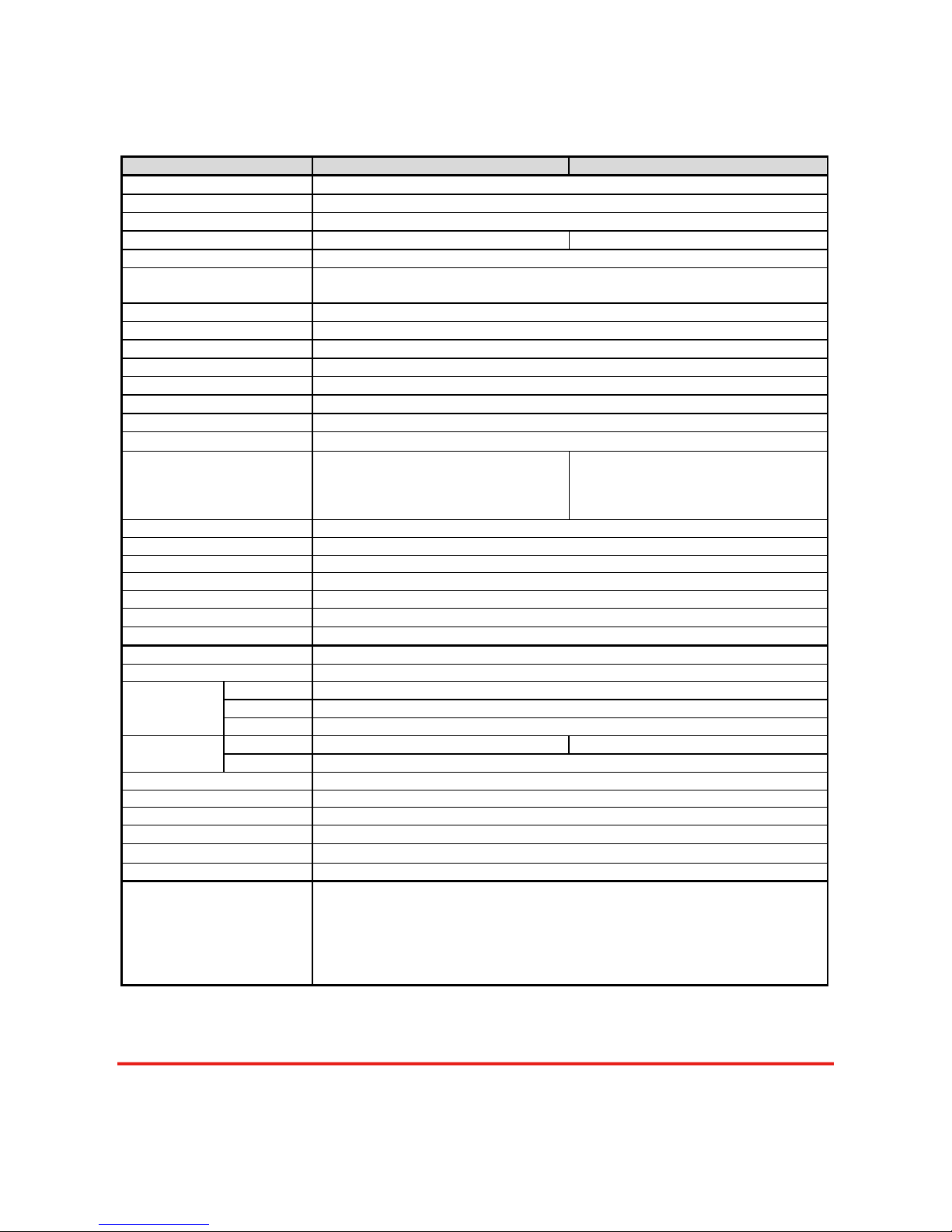
Specifications
Model Name .MX-1004 MX-1004P
Technical
Role of usage Multiplexer / video processor
Dual output support Yes [DVI & VGA]
Background video input No Yes
HDCP compliance No
Video bandwidth
DVI[Single-link 4.95Gbps] VGA[165MHz] Component [30MHz]
Composite [13.5MHz] S-Video [13.5MHz]
Video support 480i / 480p / 720p / 1080i / 1080p60 / 1920x1200@75 / 1600x1200@60
Audio support No
Control RS-232 and RS-485
Embedded video mixer Yes
Cascadable Yes
Input TMDS signal 1.2 Volts [peak-to-peak]
ESD protection Human body model — ±15kV [air-gap discharge] & ±8kV [contact discharge]
PCB stack-up
6-layer board [impedance control — differential 100Ω; single 50Ω]
Input
4x VGA + 3x DVI +
3x component + 3x composite +
1x RS-232 + 1x RS-485
4x VGA + 4x DVI + 4x component
+
4x composite + 4x S-Video +
1x RS-232 + 1x RS-485
Output 1x DVI + 1x VGA
DVI connector DVI-I [femal,29-pin]
S-Video connector 9 pin
VGA connector HD-15 [15-pin D-sub female]
RS-232 connector DE-9 [9-pin D-sub female]
RCA connector
75Ω female
RJ-45 connector WE/SS 8P8C with 2 LED indicators
Mechanical
Housing Metal case
Model 440 x 230 x 44mm [1’5.3”x9.1”x1.7”]
Package 545 x 230 x 110mm [1’9.5”x9.1”x4.3”]
Dimensions
(L x W x H)
Carton 570 x 580 x 260mm [1’10.5”x1’10.9”x10.2”]
Model 2780g [6.1 lbs]
Weight
Package
Fixedness 1U rack-mount with ears
Power supply AC Power 100-240V
Power consumption 35 Watts [max]
Operation temperature
0~40°C [32~104°F]
Storage temperature
-20~60°C [-4~140°F]
Relative humidity 20~90% RH [no condensation]
Page 6 of 18
Package Contents
1x USB to RS-232 cable
2x 1U rack mounting-ear
1x Installation software CD
1x UL AC power cord
1x User Manual
1x MX-1004 or MX-1004P
4x DVI to DVI&VGA breakout cable
3x VGA to component breakout cable
3x DVI to VGA adapter
2x DVI to DVI cable
Page 7
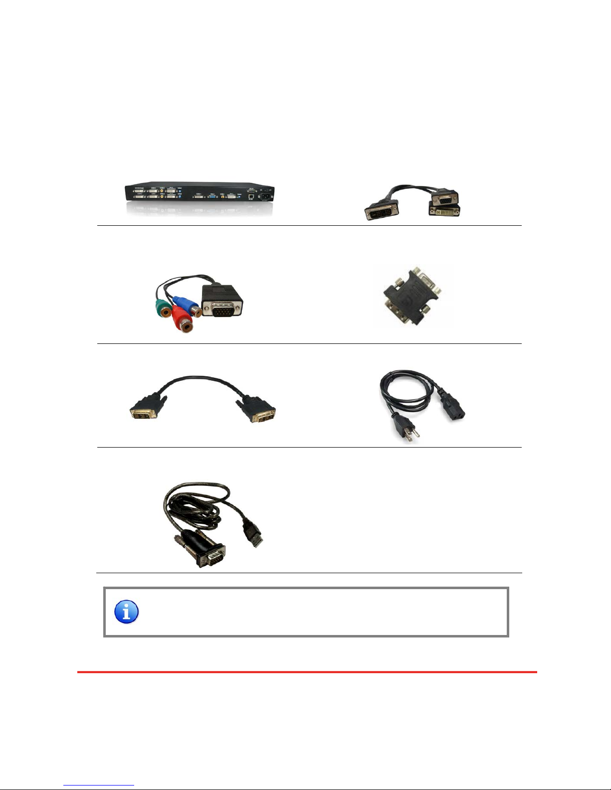
Package Contents
1. MX-1004
2. DVI to DVI&VGA Breakout
Cable
(DDVY01)
3.VGA to Component Breakout
Cable (VYPBA01)
4. DVI to VGA Adapter (DVA01)
5. 20cm DVI to DVI Cable
6. UL AC Power Cord
7. RS-232 to USB Adapter
8. 1U Rack Mounting-Ear
9. Installation Software CD
10. User Manual
Please visit
www.meicheng.com.tw
to download software &
firmware updates
Page 7 of 18
Page 8
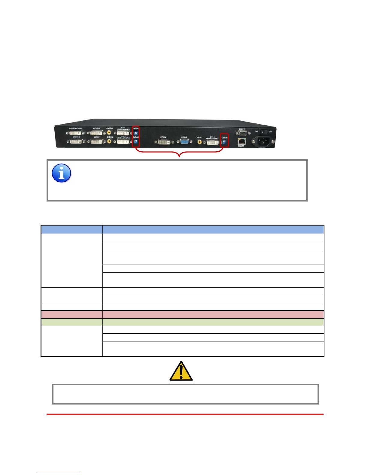
Inputs and Outputs
The MX-1004 has 10 inputs and accepts both graphics and video si gnals, which co me from computers
(DVI or VGA), composite, and component video sources respectively. You can pick up four of the ten
inputs and then display four of them simultaneously on the same screen. Figure 2 shows the rear
panel connectors of
a MX-1004 and Table 1 illustrates how you can connect video devices and display
to the
MX-1004.
*Default: Turn on the MX-1004 then switch both three DIP switches simultaneously up
and down to factory default mode.
*
These IO ports support various resolution from 640x480 up to 1920x1200, for more
detail of the supported modes, please refer to the Appendix – Supported
Resolution.
Table 1: Input/Output Connectors
Input Connector Video Source
[1] DVI
[2] VGA — with a DVI-to-VGA adapter
(DVA01)
[3] Component (YPbPr) — with a DVI-to-VGA adapter (DVA01) and a
VGA-to-component breakout cable (VYPBA01)
[4] 1x DVI + 1x VGA — with a DVI-to-DVI/VGA breakout cable (DDVY01)
DVI-x
YPbPr-x/VGA-x
[x = 1~3]
[5] 1x DVI + 1x Component (YPbPr) — with a DVI-to-DVI&VGA breakout cable
(DDVY01) and a VGA-to-component breakout cable (VYPBA01)
[1] DVI
VGA-4
[2] VGA — with a DVI-to-VGA adapter
(DVA01)
CVBS-1 ~ CVBS-4 [1] Composite — with a RCA cable
Bridge Connector 2x DVI*
Output Connector Display
[1] DVI display
[2] VGA display — with a DVI-to-VGA adapter
(DVA01)
DVI-I OUT
[3] 1x DVI display + 1x VGA display — with a DVI to DVI&VGA breakout cable
(DDVY01)
It is CRITICAL to have the DVI-to-DVI cables connected to the CONN1-CONN1 & CONN2-CONN2
sockets on the
MX-1004 for normal operation & firmware update. Please have the bridge
connectors linked at any time.
Figure 2: Rear Panel
Page 8 of 18
Page 9

Safety Precautions
I. To prevent fire or shock hazards, do not expose this device to rain or moisture.
II. When connecting other products such as DVD players, and personal computers, you should turn
off the power of this product for protection against electric shocks.
III. The product should be placed more than one foot away from heat sources such as radiators, heat
registers, stoves, and other products (including amplifiers) that produce heat. In addition, do not
cover any material or devices on the top of the device.
IV. Do not use immediately after moving from a low temperature to high temperature, as this causes
condensation,
V. Do not place this product on an unstable cart, stand, or table. The product may fall, causing
serious injury to a child or adult and serious damage to the product.
VI. Unplug this product from the wall outlet before cleaning. Do not use liquid cleaners or aerosol
cleaners. Use a damp cloth for cleaning.
VII. Do not allow the same still picture to be projected for a long time or an abnormally bright video
picture to be projected. The video image could be burned in to the display device.
Installation Procedures
Unpacking
Remove the MX-1004 from the shipping container and examine it for any signs of shipping
damage or missing items (check with package contents above). All shipping items should be saved if
the product is to be moved or returned for service. Shipping unit back to dealers for service not in the
original box may result in voiding warranty or additional cost.
Placement
The unit uses convection to cool. A fan is not needed, so do not block the sides of this device or
stack another device on the top or bottom of
the MX-1004.
Connections
We recommend the highest quality cables for both input and output connections.
1. Switch off
the MX-1004 and all devices that you want to connect.
2. Connect
CONN1
&
CONN1, CONN2
&
CONN2
by 2 DVI-to-DVI cables.
3. Connect a monitor, a projector or other displays that comes with DVI / VGA inputs by using 1
male-to-male DVI (VGA) cable to
MX-1004 DVI output (you can connect 2 displays equipped with
DVI and VGA respectively by a DVI to DVI&VGA breakout cable
(DDVY01)
).
Hardware Installation
Page 9 of 18
Page 10
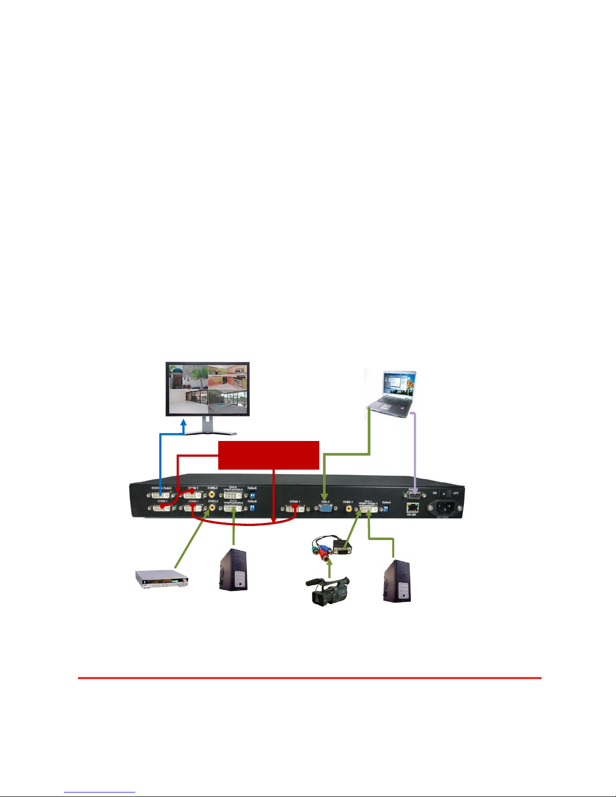
4. Plug in DVI to DVI&VGA breakout cable
(DDVY01)
to DVI-YPbPr-VGA-x and plug in VGA to
component adapter
(VYPBA01)
to the VGA connector of the breakout cable.
5. Connect a device equipped with DVI output (such as PC) to the DVI connector of the breakout
cable.
6. Connect a device equipped with component video output (YPbPr such as DVD player or camera)
to the 3-RCA jack of the
VYPBA01.
7. Connect a device equipped with VGA output (such as laptop) to the VGA connector of
MX-1004.
8. Connect a device equipped with composite video output to composite input of the
MX-1004.
9. Connect your computer with the
MX-1004 by a 9-pin RS-232 cable and then install the software.
10. Plug in AD power cord into AC power socket.
11. Execute the control software and establish the connection between PC/Laptop and
MX-1004.
12. For detailed software control operation, please refer to the software instruction section.
Must be connected in
between all the time
Component video
YPbPr
DVI
Composite video
CVBS
Connect to
RS-232
DVI
Figure 3: Connection Diagram
DVI or VGA Display
Software control
VGA
Page 10 of 18
Page 11
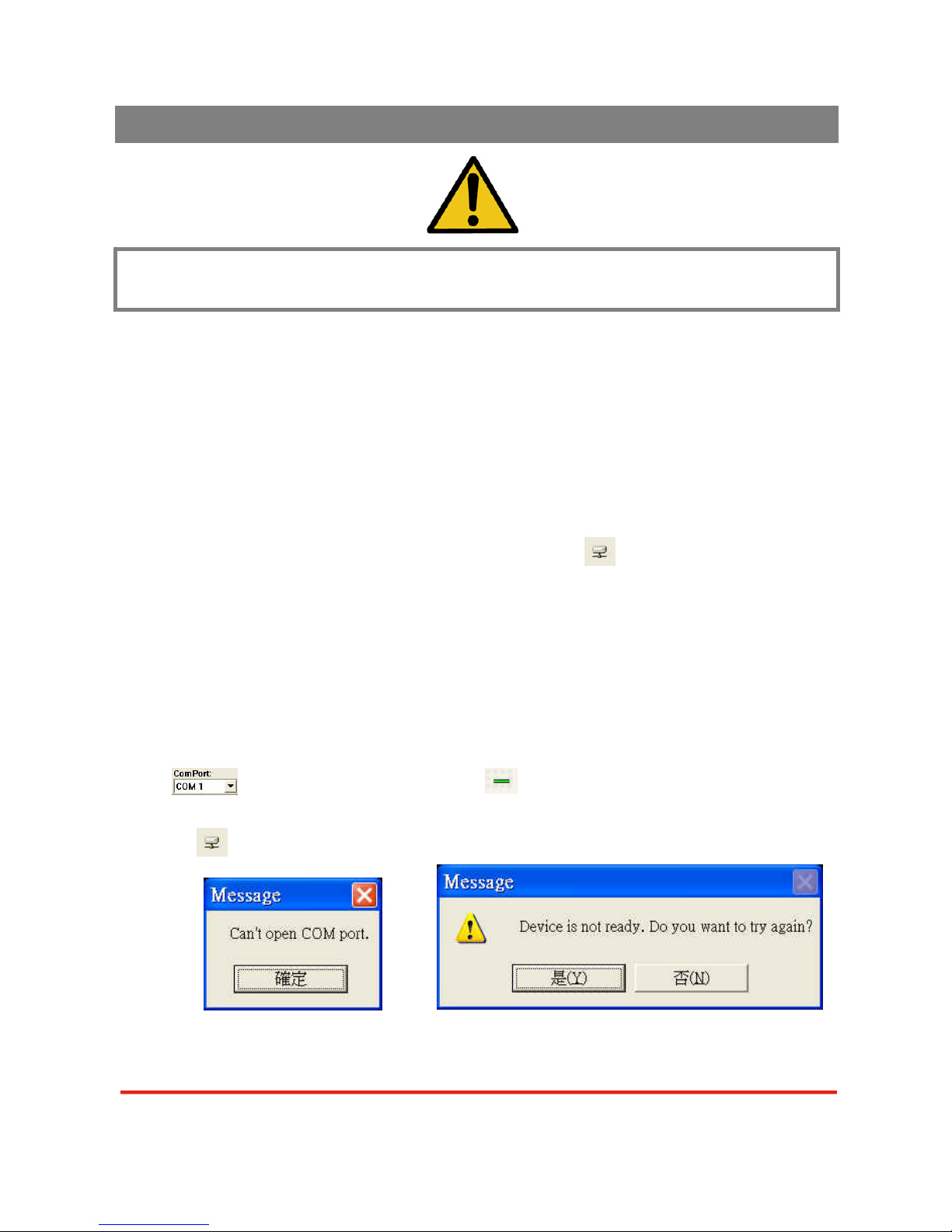
It is CRITICAL to have the DVI-to-DVI cables connected to the CONN1-CONN1 &
CONN2-CONN2 sockets on the
MX-1004 for normal operation & firmware update. Please
have the bridge connectors linked at any time.
System Requirement and Precautions
1. The MX-1004 provides a software control program, Quartet, which runs under Microsoft Windows
98, 2000, XP, Vista through the interface of RS-232 serial control.
2. Before you click on the icon of the software, make sure you have secured the connection between
your computer COM port and the MX-1004 and switched on the MX-1004 with green LED light.
3. The
MX-1004 has remote control and software control. To make sure all information shown in the
software is synchronized with those in the device, please click the update button to acquire the
latest data from the
MX-1004 after you press any key on the remote control.
Instruction of Software Connection
1. Power up the MX-1004 and you can see both red and green LEDs on the front panel blink. Make
sure the serial port (RS-232) connection secure.
2. The first step after running the software is to automatically detect if the device responses correctly
through RS-232 port. First of all, choose the correct COM port from the Com Port selection
list . Then, click on the linkage button to open the COM port. If the specified COM
port is not available, the following error message window shows up. Please check the availability
of COM Port. After the COM port is accurately established, please click on status update
button . A warning message will show up as the figure below if the serial connection is not
successfully detected.
COM Port Not Available Device Not Ready
The possible reasons causing this failure could be:
Operation Software
Page 11 of 18
Page 12
z The MX-1004 is not supplied with power Please make sure the status, and reboot the MX-1004.
z The serial connection through RS-232 is not well es tablished or some other software has taken
the available serial ports. Please make sure the RS-232 cable is well connected and the available
serial port is free to be taken by the
MX-1004.
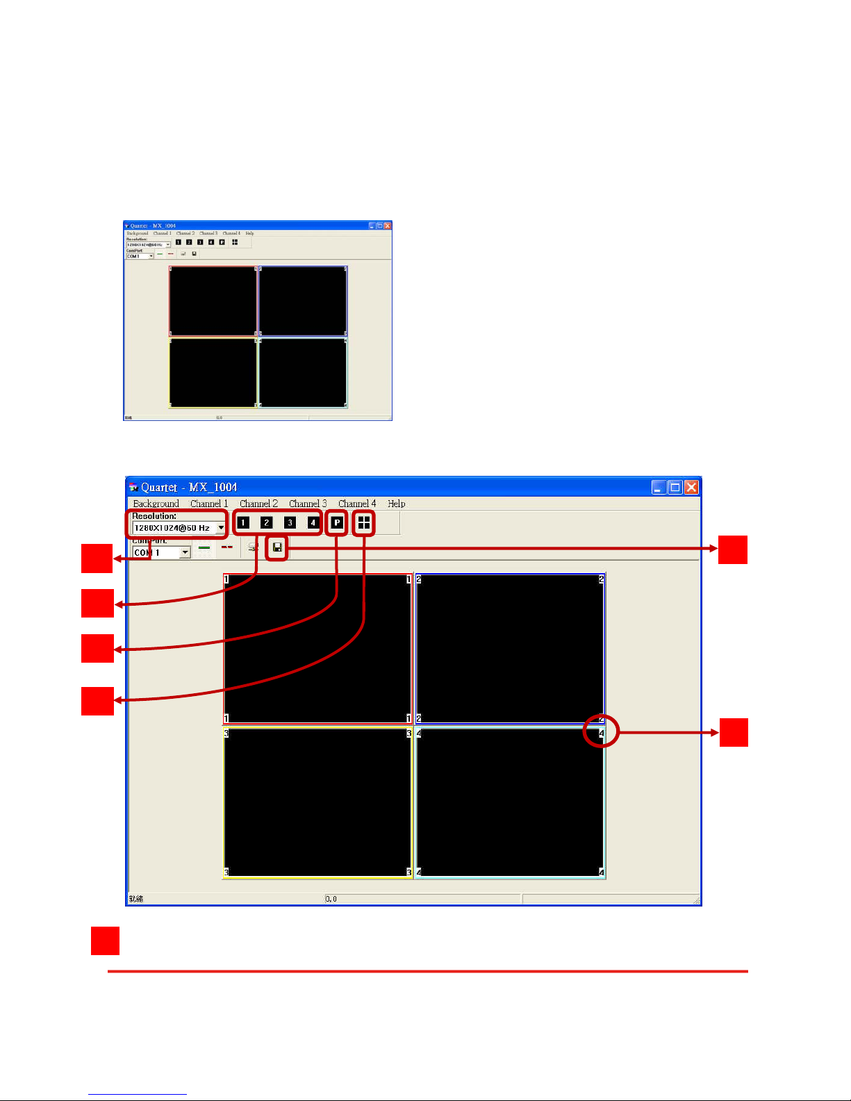
3. If the serial connection is well established, you can see work window as below.
Definitions of Menu Buttons and Icons
Output Resolution:
1
2
3
4
5
6
1
Page 12 of 18
Page 13
Quick setup for full screen display
Click on this button will make the desired display area be displayed as full screen.
Quick setup for PAP mode
This button will bring full screen mode back to PAP mode.
Quad Display mode
The functionality of this button is to expedite the default quad display. Notice that the input
sources will not be changed. Only positions and sizes will be affected.
Display area number
There are totally 4 display areas, and the numbers are 1, 2, 3, and 4.
Save Parameters for all channels
Quartet will NOT automatically save the parameters regarding size, position, and color
adjustments etc. Users MUST save all the related coefficients after the desired setup is finished.
This will keep the same display layout after the
MX-1004 is rebooted.
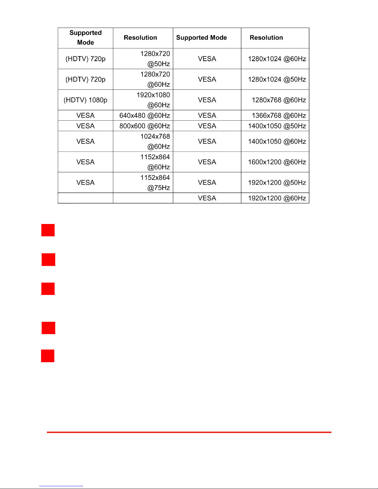
Supported
Mode
Resolution Supported Mode Resolution
2
3
4
5
6
Page 13 of 18
Page 14
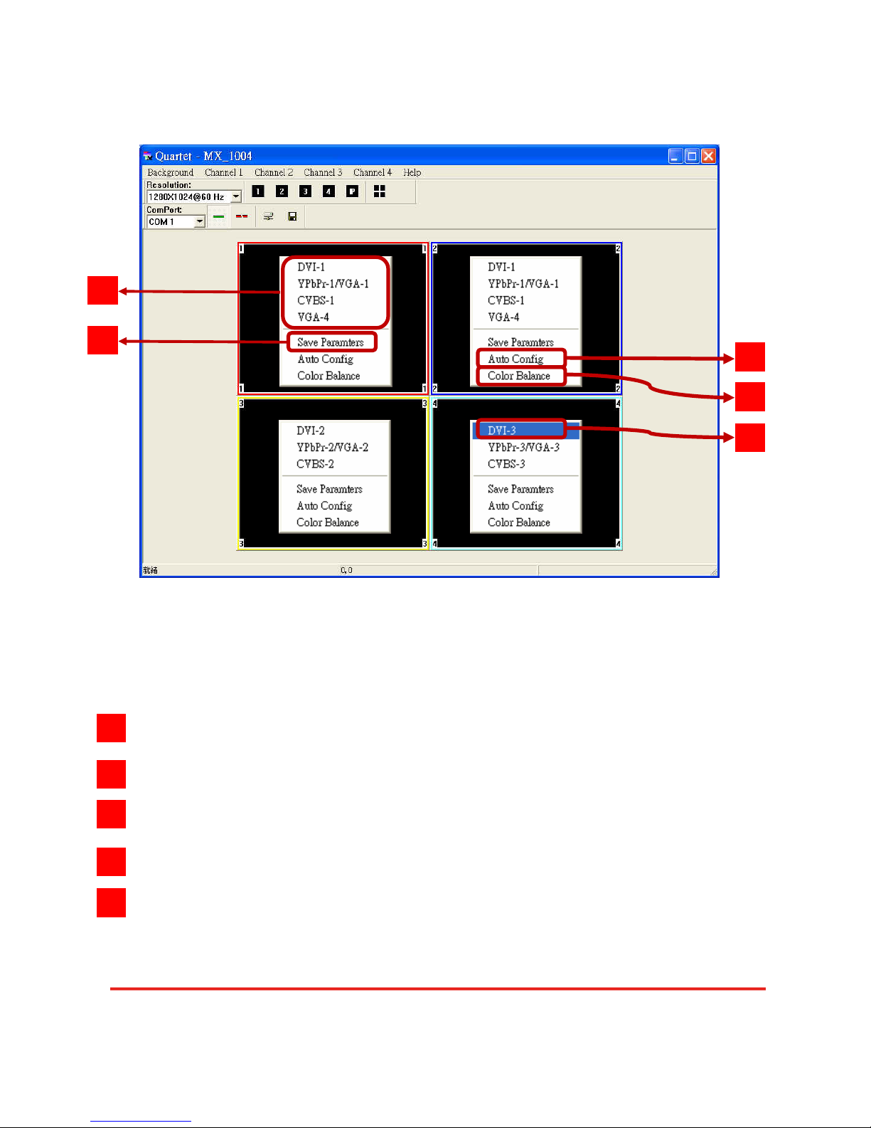
4. Display setup
Each display area has associated pop window to accelerate the selection of the input sources.
Notice that each display may not have same choices of the input sources due to the hardware
structure. On each display, clicking on the right button of the mouse will bring the control window as
shown above.
The available input sources for the corresponding display area.
The chosen input will become blue to indicate current selection.
Saves parameters for each channel.
Auto configuration for VGA inputs
Color balance for VGA and YPbPr inputs.
1
3
4
5
2
1
2
3
4
5
Page 14 of 18
Page 15
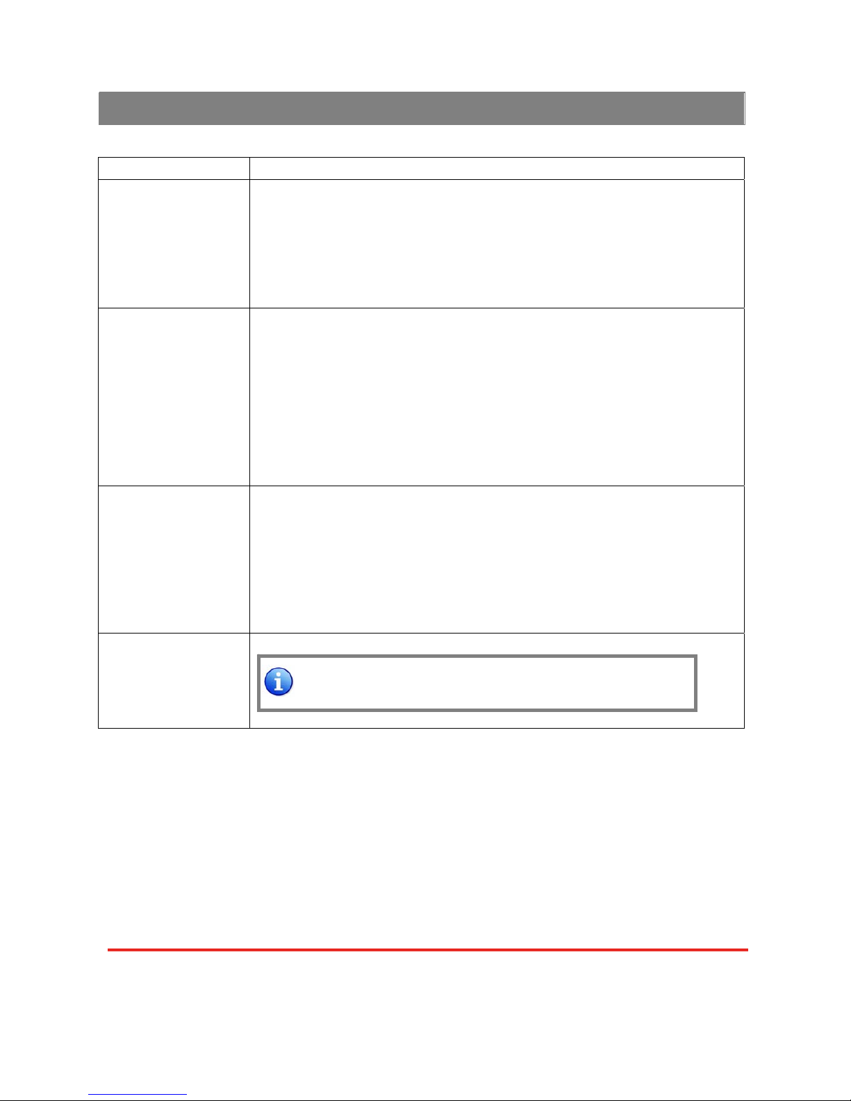
Problem Recommendations
No power
9 Check if you correctly and firmly plug AC power core into MX-1004.
9 If you are recovering from power outage, accidentally unplug the power
core or other power surge conditions, leave the device off for a while
and then power it on again.
No/ Erratic video
9 Make sure all cables are in good working condition and properly
connected to the MX-1004 and displays.
9 Configure the output video resolution so that it doesn’t excess the
native resolution of the display. ( in this case, the message of “out of
range” is usually showed on your screen)
9 Make sure video sources are accurately selected to the right channels.
Poor quality
9 We suggest that don’t use T-connectors to split your video source into
to images displayed on two different screens. That will lower output
video quality. Use a distribution amplifier instead of T-connectors.
9 Make sure the video source is not compressed and maintains the
highest native resolution.
Wrong color
9 Use color balance or auto configuration.
Auto color configuration only works at VGA and component
inputs.
Troubleshooting
Page 15 of 18
Page 16

The SELLER warrants the MX-1004 Quasi Quad-View Video Processor to be free from defects
in the material and workmanship for 1 year from the date of purchase from the SELLER or an
authorized dealer. Should this product fail to be in good working order within 1 year warranty period ,
The SELLER, at its option, repair or replace the unit, provided that the unit has not been subjected to
accident, disaster, abuse or any unauthorized modifications including static discharge and power
surges.
Unit that fails under conditions other than those covered will be repaired at the current price of
parts and labor in effect at the time of repair. Such repairs are warranted for 90 days from the day of
reshipment to the BUYER. If the unit is delivered by mail, customers agree to insure the unit or
assume the risk of loss or damage in transit. Under no circumstances will a unit be accepted without a
return authorization number.
The warranty is in lieu of all other warranties expressed or implied, including without limitations,
any other implied warranty or fitness or merchantability for any particular purpose, all of which are
expressly disclaimed.
Proof of sale may be required in order to claim warranty. Customers outside Taiwan are
responsible for shipping charges to and from the SELLER. Cables are limited to a 30 day warranty and
cable must be free from any markings, scratches, and neatly coiled.
The content of this manual has been carefully checked and is believed to be accurate. However,
The SELLER assumes no responsibility for any inaccuracies that may be contained in this manual.
The SELLER will NOT be liable for direct, indirect, incidental, special, or consequential damages
resulting from any defect or omission in this manual, even if advised of the possibility of such damage s.
Also, the technical information contained herein regarding the
MX-1004 features and specifications is
subject to change without further notice.
Limited Warranty
Page 16 of 18
Page 17
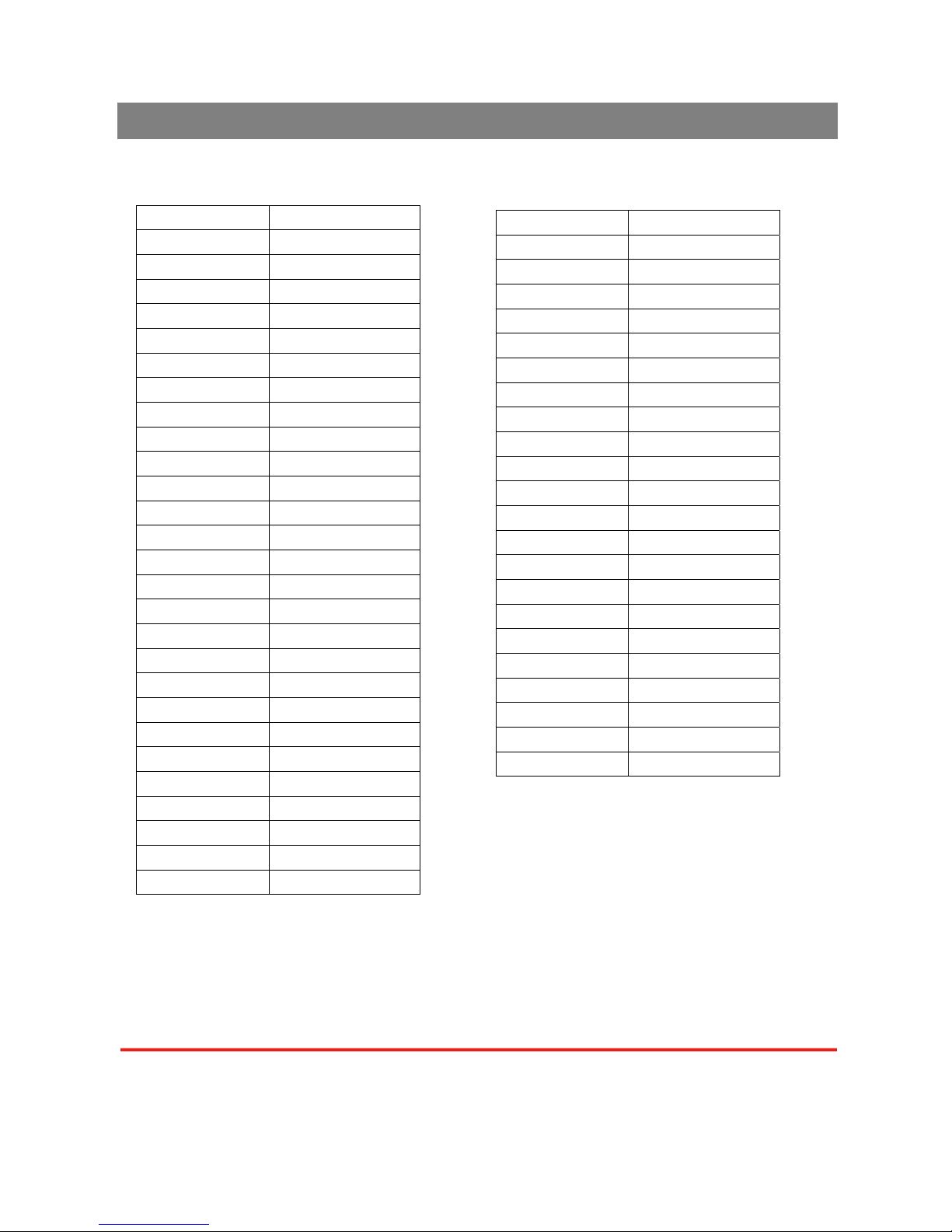
[ DVI-x / YPbPr-x / VGA-x (x = 1~3)] Socket
Supported Mode Resolution
NTSC/480I/525I 720x240 @60Hz
PAL/576I/625I 720x288 @50Hz
480P/525P 720x483 @60Hz
480P (16:9) 960x483 @60Hz
576P/625P 720x756 @50Hz
(HDTV) 720p 1280x720 @50Hz
(HDTV) 720p 1280x720 @60Hz
(HDTV) 1080i 1920x1080 @50Hz
(HDTV) 1080i 1920x1080 @60Hz
(HDTV) 1080p 1920x1080 @30Hz
VESA 720x400 @85Hz
VESA 640x350 @85Hz
VESA 640x400 @85Hz
IBM 720x400 @70Hz
IBM 720x350 @70Hz
IBM 640x350 @70Hz
IBM 640x400 @70Hz
VESA 640x480 @60Hz
MAC 640x480 @67Hz
VESA 640x480 @72Hz
VESA 640x480 @75Hz
VESA 640x480 @85Hz
VESA 800x600 @56Hz
VESA 800x600 @60Hz
VESA 800x600 @72Hz
VESA 800x600 @75Hz
VESA 800x600 @85Hz
Supported Mode Resolution
MAC 832x624 @75Hz
VESA 1024x768 @60Hz
MAC 1024x768 @60Hz
VESA 1024x768 @70Hz
IBM 1024x768 @72Hz
VESA 1024x768 @75Hz
MAC 1024x768 @75Hz
VESA 1024x768 @85Hz
VESA 1152x864 @75Hz
MAC 1152x870 @75Hz
SUN 1152x900 @66Hz
SUN 1152x900 @76Hz
VESA 1280x960 @60Hz
VESA 1280x960 @85Hz
VESA 1280x1024 @60Hz
HP 1280x1024 @60Hz
IBM 1280x1024 @67Hz
HP 1280x1024 @72Hz
VESA 1280x1024 @75Hz
SUN 1280x1024 @76Hz
VESA 1600x1200 @60Hz
VESA 1920x1200 @60Hz
Appendix – Supported Resolution
Page 17 of 18
Page 18
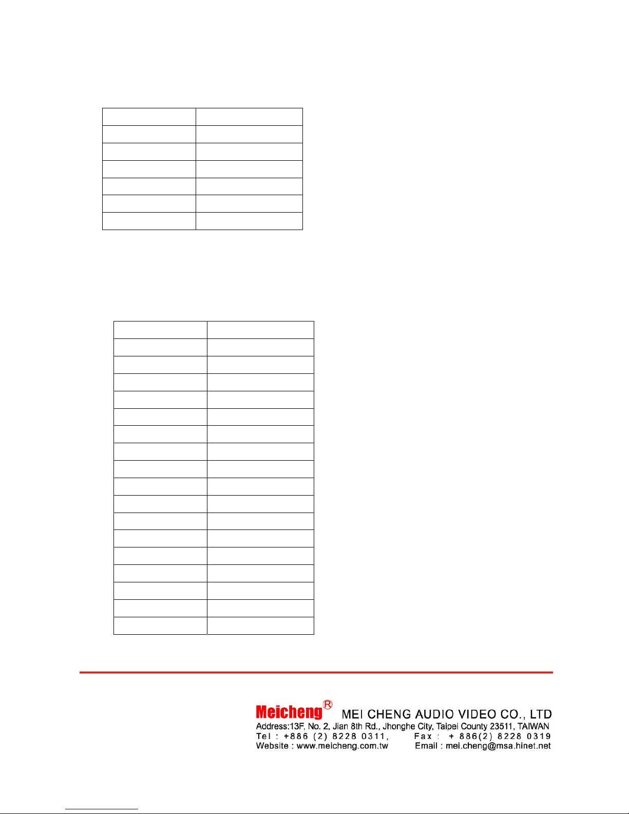
[VGA] Socket
[DVI-I OUT] Socket
Supported Mode Resolution
VESA 640x480 @60Hz
VESA 800x600 @60Hz
VESA 1024x768 @60Hz
VESA 1280x1024 @60Hz
VESA 1600x1200 @60Hz
VESA 1920x1200 @60Hz
Supported Mode Resolution
(HDTV) 720p 1280x720 @50Hz
(HDTV) 720p 1280x720 @60Hz
(HDTV) 1080p 1920 x1080 @60Hz
VESA 640x480 @60Hz
VESA 800x600 @60Hz
VESA 1024x768 @60Hz
VESA 1152x864 @75Hz
VESA 1280x1024 @60Hz
VESA 1280x1024 @50Hz
VESA 1280x768 @60Hz
VESA 1366x768 @60Hz
VESA 1400x1050 @60Hz
VESA 1400x1050 @50Hz
VESA 1152x864 @75Hz
VESA 1600x1200 @60Hz
VESA 1920x1200 @50Hz
VESA 1920x1200 @60Hz
Page 18 of 18
 Loading...