


08-01-2009
Technische Änderungen vorbehalten
MMeeiibbeess SSyysstteemm--TTeecchhnniikk GGmmbbHH
Ringstraße 18 · D - 04827 Gerichshain · Tel. + 49(0) 3 42 92 7 13-0 · Fax 7 13-50
www.meibes.de · e-mail: info@meibes.de
Technische Information für Montage und Betrieb
Technical information for installation and operation
Documentation technique pour le montage et la mise en service
Solarstation L
Solar Station L
Station solaire L
Lieferbar als 2- Strang- Solarstation
Optionen:
- Permanententlüfter
- Wicklungsschutzkontakt (WKS) für Ausführung mit Umwälzpumpe WILO Top- S 25/10
Available as double-line solar station
Options:
- Permanent air bleeder
- Thermal motor protection switch for model with circulation pump WILO Top- S 25/10
Station solaire livrable en deux lignes
Options :
- Désaérateurs permanents
- Contact de protection d’enroulement (WKS) pour un modèle avec une pompe de recirculation
WILO Top- S 25/10
GGBB
FF
DD
1
Inhalt
Table of contents
Table des matières
Kapitel Titel Chapter Title Chapitre Titre Seite/ Page/ Page
1 Sicherheitshinweise Safety notes Consignes de sécurité 2
1.1 Vorschriften/Richtlinien Regulations/Guidelines Règlements/directives 2
1.2 Bestimmungsgemäße Intended use Utilisation conforme aux
Verwendung prescriptions 4
1.3 Erstinbetriebnahme Initial start-up Première mise en service 5
1.4 Arbeiten an der Anlage Working on the system Travaux sur l’installation 5
1.5 Haftung Liability Responsabilité 6
2. Technische Daten Technical Data Caractéristiques techniques 7
3. Montage Installation Montage 10
3.1 Wandmontage Wall-mounted installation Montage mural 10
3.2 Absperrarmaturen Shut-off fittings Vannes d’arrêt 11
3.3 Thermometerwechsel Changing thermometers Echange du thermomètre 13
3.4 Sicherheitsventil Safety valve Soupape de sécurité 13
3.5 Rückflussverhinderer Backflow preventer Clapet anti-retour 14
3.6 Anschluss eines Connecting an expansion Raccordement d’un vase d’expansion
Ausdehnungsgefäßes (bauseits) vessel (provided on site) (fourni par le client) 15
3.7 Wärmeträgermedium Heat transfer medium Agent caloporteur 15
4. Druckprobe, Befüllen und Pressure Test, Filling and Evacuation, remplissage et
Spülen der Anlage Flushing the System purge de l’installation 16
4.1 Spülen und Befüllen Flushing and filling Purge et remplissage 16
4.2 Druckprobe Leak test Essai de pression 17
4.3 Entlüften Venting Purge d’air 17
4.4 Entleeren Draining Vidange 18
5. Ausführungen Versions Déclarations 19
DD
GGBB FF

2
Lesen Sie vor der Montage diese Anleitung sorgfältig durch.
Die Montage und Erstinbetriebnahme der Komplettstation
darf nur von einer zugelassenen Fachfirma ausgeführt
werden.
Machen Sie sich vor Arbeitsbeginn mit allen Teilen und deren
Handhabung vertraut.
Read through these instructions carefully before installation.
The complete station may be installed and initially started up
by an approved, qualified firm only.
Familiarise yourself with all the parts and their handling
before starting the work.
Merci de lire attentivement le présent mode d’emploi avant le
montage.
Le montage et la première mise en service de la station
intégrale doivent être effectués par une société spécialisée et
agrée. Avant de commencer le travail, familiarisez-vous bien
avec le fonctionnement de toutes les pièces.
1.1 Vorschriften/Richtlinien
Regulations/Guidelines
Règlements/directives
Beachten Sie die gültigen Unfallverhütungsvorschriften,
Umweltvorschriften und gesetzlichen Regeln für die Montage,
Installation und den Betrieb. Des weiteren die einschlägigen
Richtlinien der DIN, EN, DVGW, VDI und VDE (inkl. Blitzschutz)
sowie alle aktuellen relevanten länderspezifischen Normen,
Gesetze und Richtlinien.
Elektroanschluss:
Elektrische Anschlussarbeiten dürfen nur durch qualifiziertes
Elektrofachpersonal ausgeführt werden. Die VDE - Richtlinien
und die Vorgaben, des zuständigen EVU sind einzuhalten.
Auszug:
Thermische Solaranlagen und ihre Bauteile:
DIN EN 12975 Sonnenkollektoren
DIN EN 12976 Vorgefertigte Anlagen
DIN EN 12977 Kundenspezifisch gefertigte Anlagen
Elektrischer Anschluss:
VDE 0100: Errichtung elektrischer Betriebsmittel,
Erdung, Schutzleiter, Potentialausgleichsleiter.
VDE 0185: Allgemeines für das Errichten von
Blitzschutzanlagen.
VDE 0190: Hauptpotentialausgleich von
elektrischen Anlagen.
Zusätzliche Richtlinien und Hinweise:
VDI 6002 Blatt 1 Allgemeine Grundlagen,
Systemtechnik und Anwendung im
Wohnungsbau
VDI 6002 Blatt 2 Anwendungen in Studenten-
wohnheimen, Seniorenheimen,
Krankenhäusern, Hallenbädern und
auf Campingplätzen
1. Sicherheitshinweise
Safety notes
Consignes de sécurité
DD
FF
GGBB
DD
- Vor Gebrauch Monteageanleitung lesen
- Read the assembly instructions before use
- Avant l'utilisation, lire les instructions de montage
- Schnittgefahr
- Risk of cutting
- Risque de se couper
- Quetschgefahr
- Risk of crushing
- Risque de se couper
- Gefahr erhöhter Temperatur
- Risk of increased temperature
- Risque de haute température
- Gefahr elektrischer Spannung
- Risk of electrical voltage
- Danger dû à la tension électrique
- Sturzgefahr bei der Montage
- Risk of dropping during assembly
- Risque de tomber lors du montage

3
Note and observe the accident prevention regulations/health
& safety regulations, the environmental regulations and the
statutory regulations for assembly, installation and operation.
Furthermore, the relevant guidelines of the DIN, EN, DVGW,
VDI and VDE (incl. lightning protection) as well as all relevant
country-specific standards, laws and guidelines.
Electrical connection:
Electrical connection work may only be carried out by
qualified electricians. The VDE guidelines and regulations of
the electrical utility company responsible must all be
complied with.
Extract:
Thermal solar systems and their components:
DIN EN 12975 Solar collectors
DIN EN 12976 Prefabricated systems
DIN EN 12977 Custom built systems
Electrical connection:
VDE 0100: Construction of electrical equipment,
earthing, protective conductors,
equipotential conductors.
VDE 0185: General information for the installation of
lightning protection systems.
VDE 0190: Main equipotential bonding of electrical
systems.
Additional guidelines and notes:
VDI 6002 Part 1 General principles, systems engineering
and use in housing
VDI 6002 Part 2 Uses in student hostels, retirement
homes, hospitals, indoor swimming pools
and on camping sites
Respectez les règlements en vigueur relevant de la prévention
des accidents, de la protection de l’environnement et les
règlements législatifs concernant le montage, l’installation et
le fonctionnement. Par ailleurs, respectez également les
directives correspondantes et conformes aux normes DIN, EN,
DVGW, VDI et VDE (protection contre la foudre inclue) ainsi
que toutes les normes, lois et directives en vigueur dans
haque pays.
Raccordements électriques :
Les travaux de raccordements électriques doivent être
effectués uniquement par un électricien agrée. Les directives
de l’Association de l’électrotechnique, de l’électronique et de
la technique d’information (Verband der Elektrotechnik,
Elektronik und Informationstechnik «VDE») et les prescriptions
du distributeur d’énergie compétent sont à respecter.
Extrait :
Installations solaires thermiques et leurs éléments de
construction :
DIN EN 12975 Collecteurs de soleil
DIN EN 12976 Installations préfabriquées
DIN EN 12977 Installations fabriquées sur mesure
Raccordements électriques :
VDE 0100: mise en service de matériaux électriques,
mise à la terre, conducteurs de protection,
conducteurs d’équipotentialité.
VDE 0185: généralités concernant la mise en service
d’installations de protection contre
la foudre.
VDE 0190: conducteur principal d’équipotentialité
sur des installations électriques.
Consignes et directives supplémentaires :
VDI 6002 Feuille 1 Généralités de base, génie des systèmes
techniques et utilisation dans le bâtiment
VDI 6002 Feuille 2 Utilisation dans les foyers d’étudiants,
résidences pour personne du troisième
âge, hôpitaux, piscines couvertes et
campings.
FF
GGBB
1. Sicherheitshinweise
Safety notes
Consignes de sécurité

4
1.2 Bestimmungsgemäße Verwendung
Intended use
Utilisation conforme aux prescriptions
Die beschriebenen Stationen sind nur mit geeigneter und
zugelassener Solarflüssigkeit zu betreiben. Es ist auf einen
ausreichenden Frostschutzgehalt zu achten.
Die Verwendung eines anderen Mediums ist nicht zulässig.
Medientemperatur > 60 °C (Verbrühungsgefahr)
Soll- bzw. Befülldruck < Ansprechdruck der
Sicherheitsarmatur
Alle Absperrarmaturen dürfen nur vom zugelassenen
Fachmann im Servicefall und bei abgedeckten
Kollektoren geschlossen werden, da ansonsten die
Sicherheitsarmaturen ihre Wirkung verlieren.
Nehmen Sie keine Veränderungen an den elektrischen
Bauteilen, der Konstruktion oder den hydraulischen
Komponenten vor! Sie beeinträchtigen sonst die sichere
Funktion der Anlage.
The described station is intended for primary operation of the
solar substation with propylene glycol - water mixtures. Use
of other media is not allowed.
Media temperature > 60 °C (Risk of scalding)
Setpoint and filling pressure < pickup pressure of the
safety fitting
All shut-off fittings may be closed in the service case
only and only if the collectors are covered as otherwise
the safety fittings lose their effect.
Caution:
Do not make any changes to electrical components, the design
or the hydraulic components! Otherwise you will impair the
safe function of the system.
La station décrite est prévue pour le fonctionnement primaire
de la station de transmission solaire avec un mélange à base
de propylène glycol et eau. L’utilisation d’un autre agent n’est
pas autorisée.
Température de l’agent > 60 °C (danger d’échaudement)
Pression de consigne ou < pression de démarrage de la
de remplissage vanne de sécurité
Les vannes d’arrêt ne doivent être fermées qu’en cas de
nécessité et avec les capteurs recouverts, sinon elles
perdraient de leur effet.
Attention :
N’effectuez aucune transformation des composants
électriques, de la construction en elle-même ou des
composants hydrauliques ! Sinon vous compromettez le bon
fonctionnement de l’installation.
DD
FF
GGBB
1. Sicherheitshinweise
Safety notes
Consignes de sécurité

5
1. Sicherheitshinweise
Safety notes
Consignes de sécurité
1.3 Erstinbetriebnahme
Initial commissioning
Première mise en service
Vor der Erstinbetriebnahme ist die Anlage auf Dichtheit, eine
korrekte hydraulische Anbindung sowie sorgfältige und
korrekte elektrische Anschlüsse zu prüfen. Des weiteren ist
eine sorgfältiges bzw. bedarfsgerechtes Spülen gemäß
DIN 4753 der Anlage durchzuführen. Die Erstinbetriebnahme
hat durch eine geschulte Fachkraft zu erfolgen und ist schriftlich zu protokollieren. Darüber hinaus sind die Einstellwerten
schriftlich festzuhalten.
Die technische Dokumentation hat am Gerät zu verbleiben.
Before the initial commissioning, the system must be checked
for any leakage as well as to make sure the hydraulic linkage
is correct and that the electrical connection work has been
carried out with care and correctly. The system must also be
carefully flushed in accordance with DIN 4753. The initial
commissioning must be carried out by a trained specialist and
a written record of it must be drawn up. In addition to this, the
settings must also recorded in writing. The technical
documentation must remain with equipment.
Avant la première mise en service, il faut vérifier l’étanchéité
de l’installation, le bon branchement des raccords
hydrauliques et un travail de raccordement électrique correct.
De plus, il faut effectuer une purge minutieuse
de l’installation conformément à la norme DIN 4753.
La première mise en service doit être effectuée par du
personnel formé et spécialisé et un compte-rendu doit être
fait par écrit. Par ailleurs, les valeurs d’ajustement sont à
noter. La documentation technique doit toujours se trouver à
proximité de l’appareil.
DD
FF
GGBB
1.4 Arbeiten an der Anlage
Working on the system
Travaux sur l’installation
Die Anlage ist spannungsfrei zu schalten und auf
Spannungsfreiheit zu kontrollieren (z.B. an der
separaten Sicherung oder einem Hauptschalter).
Anlage gegen Wiedereinschalten sichern.
Die Kollektoren sind abzudecken, um das System abzukühlen.
ACHTUNG: Verbrühungsgefahr:
Medientemperatur > 60°C
The system must be disconnected from the power supply and
checked to ensure it is safely isolated from the power supply
(e.g. at the separate fuse or a master switch).
Secure the system against being switched back on again.
IMPORTANT: Risk of scalding:
Media temperature > 60°C
L’installation doit être mise hors tension, celle-ci devant être
contrôlée (par exemple sur les fusibles séparés
ou sur le commutateur principal). L’installation doit être
protégée contre toute nouvelle mise en circuit.
ATTENTION: Danger d’échaudement:
Température de l’agent > 60°C
DD
GGBB
FF
6
1. Sicherheitshinweise
Safety notes
Consignes de sécurité
1.5 Haftung
Liability
Responsabilité
Für diese Unterlage behalten wir uns alle Urheberrechte vor.
Missbräuchliche Verwendung, insbesondere Vervielfältigung
und Weitergabe an Dritte ist nicht gestattet.
Diese Montage- und Bedienungsanleitung ist dem Kunden zu
übergeben. Das ausführende bzw. zugelassene Gewerke (z.B.
Installateur) hat dem Kunden die Wirkungsweise und
Bedienung des Gerätes verständlich zu erklären.
We reserve all copyrights to this document.
These installation and operating instructions must be handed
over to the customer. The skilled trades carrying out the work
(e.g. fitter) must explain to the customer how the equipment
works and how to operate it in a way they can understand.
Nous nous réservons les droits d’auteurs pour le présent
document. Le mode d’emploi du montage et de l’utilisation
doit être remis au client. Le personnel qualifié (par exemple
l’installateur) doit instruire le client de manière
compréhensive de l’utilisation correcte et des effets
de l’appareil.
DD
GGBB
FF
7
2. Technische Daten
Technical Data
Caractéristiques techniques
Für den Einsatz in thermischen Solaranlagen bis ca. 50 m
2
Kollektorfläche. (In Abhängigkeit von Typ und vorherrschenden/bestehenden Anlagenparametern)
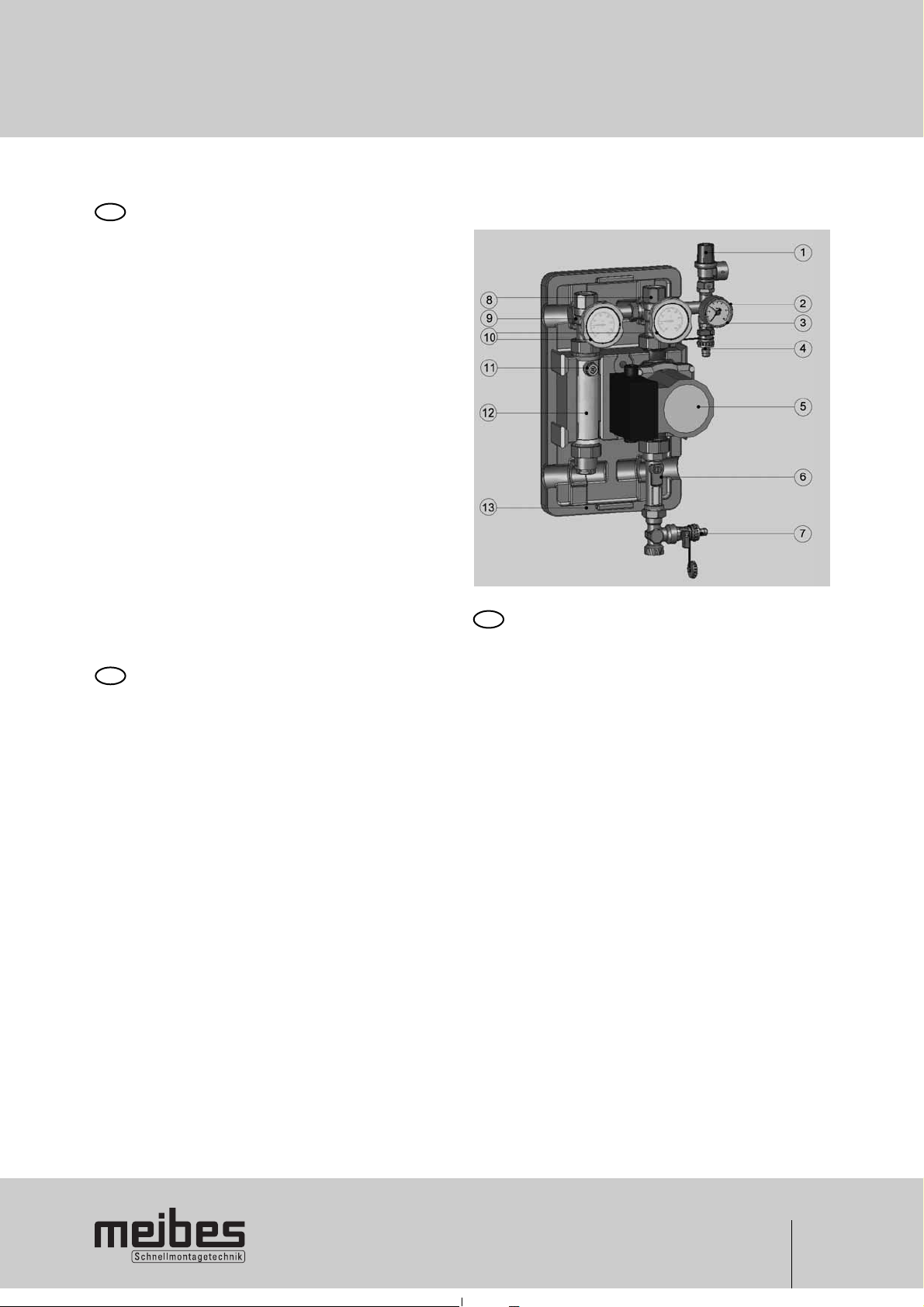
Die Solarübergabestation wird als 2- Strangausführung vormontiert geliefert. Ausdehnungsgefäße und Zubehör sind
nicht im Lieferumfang enthalten und müssen den anlagentechnischen Erfordernissen montiert werden.
1 Sicherheitsventil
2 Anschluss für Ausdehnungsgefäß (verdeckt)
3 Manometer
4 KFE- Hahn mit Kappe und Schlauchtülle
5 Umwälzpumpe
6 Volumenstrombegrenzer
7 KFE- Hahn mit Kappe und Schlauchtülle
8 Absperrkugelhahn 1“IG x 1 1/2“IG-Überwurfmutter mit
integrierter Schwerkraftbremse
9 Absperrkugelhahn 1“IG x 1 1/2“IG-Überwurfmutter mit
integrierter Schwerkraftbremse (handaufstellbar)
10 Kugelhahngriff mit integriertem Thermometer
11 Schnellentlüfter
12 Permanententlüfter
13 Blockisolierung
For use in thermal solar collector systems with collector areas
of up to approx 50 m
2
(Depending on model and
prevailing/existing system parameters)
The solar transfer station comes prefabricated with a doubleline design. It does not come with expansion tanks or
accessories, which have to be installed to meet the system
requirements.
1 Safety valve
2 Connection for expansion tank (concealed)
3 Pressure gauge
4 Ball valve for filling and draining with cap and hose
connector
5 Circulation pump
6 Volume flow limiter
7 Ball valve for filling and draining with cap and hose
connector
8 Shut-off ball valve 1" internal thread x 1 1/2" internal-
thread coupling nut with integrated gravity brake
9 Shut-off ball valve 1" internal thread x 1 1/2" internal-
thread coupling nut with integrated gravity brake
(manually positionable)
10 Ball valve handle with integrated thermometer
11 Quick air-bleeder
12 Permanent air bleeder
13 Block insulation
Pour une utilisation dans les installations solaires thermiques
ayant une surface de récupération allant jusqu’à env. 50 m
2
.
(Dépendant du type et des paramètres de l’installation
prédominants/préexistants)
La station de transmission solaire est livrée avec deux lignes
en tant qu’unité prémontée. Les vases d’expansion et autres
accessoires ne sont pas compris dans le volume de livraison
et doivent être montés conformément aux exigences
techniques de l’installation.
1 Soupape de sécurité
2 Raccordement pour un vase d’expansion (caché)
3 Manomètre
4 Robinet d’arrêt à boisseau sphérique avec capuchon et
raccord d’extrémité
5 Pompe de recirculation
6 Limiteur de débit volumétrique
7 Robinet d’arrêt à boisseau sphérique avec capuchon et
raccord d’extrémité
8 Robinet d’arrêt à boisseau sphérique 1“IG x 1 1/2“IG-
écrou-raccord avec frein à commande par gravité intégré
9 Robinet d’arrêt à boisseau sphérique 1“IG x 1 1/2“IG-
raccord avec frein à commande par gravité intégré
(réglable manuellement)
10 Poignée du robinet d’arrêt à boisseau sphérique avec
thermomètre intégré
11 Désaérateurs rapides
12 Désaérateurs permanents
13 Bloc isolant
DD
FF
GGBB
8
2. Technische Daten
Technical Data
Caractéristiques techniques
DD
FF
GGBB
Anschlüsse : Solarkreis : 1"IG
Speicherkreis : 1“AG
für Ausdehnungsgefäß : 3/4"AG
max. zul. Temperatur : +110 °C, kurzzeitig +130 °C (max. zul. Temp. der Pumpe beachten!)
max. zul. Druck : 6 bar (Ansprechdruck Sicherheitsventil beachten!)
Rückflussverhinderer : 2-Strang: 2x 200 mmWs
Volumenstromanzeiger : 10 ... 40 l/min
Thermometer : Anzeigebereich 20 ... 150 °C
Manometer : Anzeigebereich 0 ... 10 bar
Sicherheitsventil : Ansprechdruck 6 bar
Abmessungen gesamt : Höhe : 420 mm
Breite : 250 mm
Tiefe : 246 mm
Achsabstand : 125 mm
Connections : Solar circuit : 1"internal thread
Storage tank circuit : 1“external thread
for expansion vessel : 3/4"external thread
Max. temperature allowed : +110 °C, short-term +130 °C (note max allowable temp of the pump!)
Max. pressure allowed : 6 bar (note pick-up pressure of safety valve!)
Backflow preventer : 2-branch: 2x 200 mmWs
Volume flow indicator : 10 ... 40 l/min
Thermometer : Display range 20 ... 150 °C
Pressure gauge : Display range 0 ... 10 bar
Safety valve : Pick-up pressure 6 bar
Dimensions, overall : Height : 420 mm
Width : 250 mm
Depth : 246 mm
Centre to centre spacing : 125 mm
Raccords : Circuit solaire : 1"IG
Circuit du chauffage : 1“AG
pour vase d’expansion : 3/4"AG
Température max. admise : +110 °C, brièvement +130 °C (attention à la température max. admise de la pompe!)
Pression max. admise : 6 bar (attention à la pression de démarrage de la soupape de sécurité!)
Clapet anti-retour : 2-lignes: 2x 200 mmWs
Indicateur de débit volumique : 10 ... 40 l/min
Thermomètre : Plage d’affichage 20 ... 150 °C
Manometer : Plage d’affichage 0 ... 10 bar
Soupape de sécurité : Pression de démarrage 6 bar
Dimensions totales : Hauteur : 420 mm
Largeur : 250 mm
Profondeur : 246 mm
Entraxe : 125 mm
 Loading...