

ST-IIIB user manual
P/N 20130320-1

Us er ma nual
产品手 册
Brief
Dear customer:
Congratulations on purchasing you new security systeman thank
you for the confidence you have shown in us.You have chosena high
-quality.
Product that has been produced,tested and packed wthegreatest
care.Please familiarize yourself with these instructions before atte
mpting operation will only been sure if it is fitted properly.We hope your
new security system will bring you lasting pleasure.

Us er ma nual
产品手 册
Content
Chapter I Introduction 1
Chapter 2 Installation and Connection 4
2.1 Installation 4
2.2 Connection(N.O. N.C) 4
2.3 Install wired detector 4
2.4 Intall wereless detector 5
Chapter 3 Keybad and Operation 5
3.1 About panel 5
3.2 Basic operation 7
3.3 Flashes when phone line cut 7
3.4 Host arm and disarm 8
3.5 Alarm procedure 10
Chapter IV Voice alarm receiving 11
and GSM con trol
4.1 Remote phone control 11
4.2 Alarm receiving phone operation 11
4.3 GSM remote operation 12
4.4 GSM alarm receiving 12
4.5 GSM control via SMS 12
Chapter IV Voice alarm receiving and GSM control 13
5.1 Set system clock 13
5.2 Set user password 13
5.3 Set voice phone 13
Chapter VI System Setting 1 4
6.1 Set password 14
6.2 Set CMS number 15
6.3 Set voice phone 16
6.4 Set system options 17
6.4.1 Set system clock 17

Us er ma nual
产品手 册
6.4.2 Set entry delay 18
6.4.3 Set exit delay 18
6.4.4 Set siren time
6.4.5 Set ring times 18
6.4.6 Set detector loss inspection 19
6.4.7 Set arm/disarm tone 19
6.4.8 Set arm/disarm report 20
6.4.9 Set others 2 0
6.5 Manage wireless device 23
6.5.1 Set remote control 2 3
6.5.2 Set detector 2 4
6.5.3 Set appliance switch 2 5
6.5.4 Enroll wireless siren 2 6
6.6.5 Set door bell 2 7
18
6.4.9.1Set emergency alarm siren type 20
6.4.9.2 Ac off inspection time setting 21
6.4.9.3 Magnetic contact inspection 21
6.4.9.4 Check wireless detector tamper 21
6.4.9.5 Set force arm 2 1
6.4.9.6 Set telehpone line disconnect remind 22
6.4.9.7 Set zone alrm times 2 2
6.4.9.8 Set listen-in time 2 2
6.4.9.9 Set AC off remind 23
6.5.1.1 Enroll remote control 2 3
6.5.1.2 Enter remote control code 2 4
6.5.1.3 Delte remote control 2 4
6.5.2.1 Detector coding 2 4
6.5.2.2 Enter detector code 2 5
6.5.2.3 Delete detector 25
6.5.3.1 Enroll appliance switch 2 5
6.5.3.2 Delete appliance switch 26
6.5.4.1 Enroll wireless siren 2 6
6.5.4.2 Delete wireless siren 2 6
6.5.5.1Enroll doorbell 27
6.5.5.2 Delete doorbell 27

Us er ma nual
产品手 册
6.6.1 Set zone attribution 28
6.6.2 Set zone siren type 28
6.6.3 Set wired zone loop type 28
6.6.4 Set wired zone response speed
6.6.5 Set related zone
6.7 System maintance 30
6.7.1 Set timing operation 31
6.7.2 Recording 31
6.7.3 Play recording 31
6.7.4 Set programmable output port 31
6.7.5 Delete system events 32
6.7.6 Restore to factory default 32
6.8 Set GSM m odule 3 2
6.9 Advanced setting options 34
6.9.1 GPRS enable and disable
6.9.2 Set sever IP address 35
6.9.3 Set sever port 36
6.9.4 Set user ID 36
6.9.5 Set user password 36
6.9.6 GSM SMS language 36
6.9.7 Delay zone tone source options 37
6.9.8 Handshake tone input signal intensity 37
6.9.9 DTMF output signal intensity 37
6.9.10 Set LCD standby brightness 37
6.9.11 Alarm event retain time 38
Chapter VII technical specification 39
7.1 General data 39
7.2 Physical performance 39
Chapter VIII maintenance 4 0
8.1 Regular test 40
8.2 The cleanliness of control mai n machine 40
Chapter VX limitation of the products 40
29
29
35

Us er ma nual
产品手 册
Chapter I Introduction
1.1 Function Introduction
、
I Alarm mode: with P STN and G SM network alarm, GSM n etwork wit h
GPRS fu nction(GPRS function is for China market only), remote arm and
disarm panel through CMS or SMS CID protocol, SMS notification, the
priority of PSTN an d GSM network is Optional.
2、
With a new large-screen, full-touch buttons, LCD graphic display steps,
work st atus,Ala rm process easy and intuitive.
3、
The full English voice prompting operation: all local or remote operat ion,
alarm i nformation, event log view.
4
、GSM-h ook and voice telephone with intercom function.
5、All alarm information can be programmed for the following settings:
0 does no t send any information
1,Sen d only SMS 2,O nly call users 3,SMS + cal l user 4, CMS only
5 ,CMS + SM S. 6,CMS + cal l user 7. CMS + SM S + call user
6、Sleep mode: Under sleep mode, all the lights, backlight, voice and
remin d tone are disabled.
7、Alarm panel under idle status is equivalent to a cellphone, you can call
throu gh the GSM network for balance inquiries
8、The associated zone: 4 groups associated zone, three kinds of
assoc iation patterns, can effectively reduce false alarm or for other
funct ions.
9、PGM output: With a programmed output port, followed by five kinds of
alarm e vents output.
10、The doorbell Audio O ptional:
1. Ding D ong 2 Welcome 3. Re cording 4. D ee-Dee~
11、Remote phone operation: dialing by telephone offsite , after pass word
verif ication, you can arm, disarm, listen-in premise, system status query
and ele ctrical switches controls and other operations.
12、Voice Alar m: When pane l alarm, it wi ll automat ically dia l the preset u ser
phone numbers to report alarm information then you can remote control
the pan el after enter user passwords.
1

Us er ma nual
产品手 册
13、Wireless zones, each wireless zone can automatically learn the code s
or be cod ed manually via the keyboard.
14、8 wired zones, User can set the circuit type and speed of
respo nse, support N.O, N.C.
15、Enable enroll total 8 wireless remote,8 electronic switch,1 pc of wir ele-
ss door bell and Unlimited for quantity of one way wireless siren.
16、 Follow me phone #,two for CMS,four for private alarm receiving.
17、Status inspection function:Enable record and inquiry 120 alarm ev ent
messa ges.Like the time when happens anti-tam per alarm,detector alarm,
tel-l ine off,arm,disarm,system setting,battery low volt age etc.And also
can inq uiry the zone number and alarm type.
Tim ing arm and disarm: 4 sets of timing arm and disarm time.
18、
19 Electrical switches control: User can remote switch on/off via phone or
、
SMS, al so can be controlled manually through the local alarm panel.
20 Zone programmable: factory preset for each zone type. Users
、
can mod ify all the zone type according to the actual needs .
21 Clock: Built-in full automatic calendar clock, set to local time
、
consi stent
Password access management: the panel has one administrator
22、
passw ord 16 user password, The administrator password primarily for
syste m administrators to set up the alarm system; The user passwords
for use rs in the day-to-day use such arm/ disarm,remote operation. The
admin istrator password, user password can be freely modified.
23、For CMS
can set f our, six or eight user codes(account number).
、
24 Zone type identification:After an alarm is triggered, the alarm zone
numbe r displayed on the LCD screen of the panel, also can send the
detai led report to CMS which includes alarm locations and zone types.
25、Al-proof function:If try to cut off the wire between wered detector and
panel o r cut off the tel line which.
networking alarm, depending on the number of users, the user
2

Us er ma nual
产品手 册
The tampering alarm: cut the cable between wired detectors and the
26、
will tr igger larm, the telephone line cut will autom atically trigger siren alarm.
When so meone deliberately dismantled the panel, it will alarm when
trigg ering tamper switch at the back of the panel.
27 Timing arm/disarm:Enable set 4 group time arm/disarm time.
、
28 CMS communications test: The pan el will send a m essage to CM S at the
、
pre-s et time interval to inspect the communicaiton if normal.
29 Siren options:Built-in siren, external wired siren, Wirelss sir en. All si rens
、
can be pr ogrammed as enabled/disbale when alarms.
30 The voice speaker volume adjustment: adjust the volume by a rotary
、
switc h on the panel.
31 Wireless repeater function:can extend the distance between the de tector
、
and the p anel by adding a wireless repeater of our company.
32 The wireless detector low battery prompted:Detectors will send status
、
repor t to the panel every 1-3 hours, the corresponding zone number and
the bat tery volta ge symbol will be displayed on the LCD screen and also
will re port to CMS.
panel
3
Us er ma nual
产品手 册
Chapter 2 Installation and Connection
Installation
2.1
Fix the bracket to the wall and hang the pane to the bracket
1.
The large metal objects can not be placed around the panel, so as not to
2.
affect the w ireless si gnal.
Make sure to place the panel within the wireless range of all wireless
3.
acces soris and pay attention to the hidden
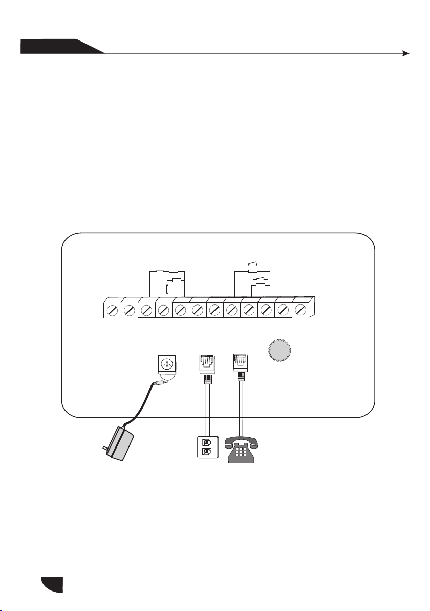
2.2 Connection(N.O. N.C)
As pictures
10 K
NC
10 K
NC
PGM G ND Z33 Z 34 GND Z 35 Z36 Z 37 Z38 G ND Z39 Z 40
N. ON. C
NO
NO
10 K
10 K
DC15V/2A
Pow er
LIN E
TEL L
Voice volume
kno bs
Her e o nl y i ntr odu ce th e z one 3 3, 34, 3 7, 38. T he oth er zo nes pl ease
refer to the above.
2.3 Install wired detector
2.3.1The wired zones is disabled factory default. when to use wired zone s
pleas e enable the zones firstly.When wired zones is in trouble, the
panel w ill voice prompt "operation fails, Zone trouble” if users try
4
Us er ma nual
产品手 册
To ar m the panel. The zo ne number wi ll be also dis play on the LC D
scree n. At this time a rm system is n ot allowed unless you force arm.
2.3.2
The control pane can power 15V, 100mA to detectors. The max curent
is 100m A. Do not exceed 100mA, otherwise please use extra power
suppl y.
2.4 Intall wereless detector
2.4.1 As t he detector`s manual says,install coded detector in the area
from th e control pa nel.Please test and make sure detector can work with
contr ol panel nor mally.
2.4.2 W ireless repeater function:when wireless detector is too far from the
panel o r some occlu ders between panel and detector which disable the
panel r eceiveth e signal from wireless detector.Now you can choose our
made wi reless rep eater to achieve wireless signal relay trans mitting.
Chapter 3 Keybad and Operation
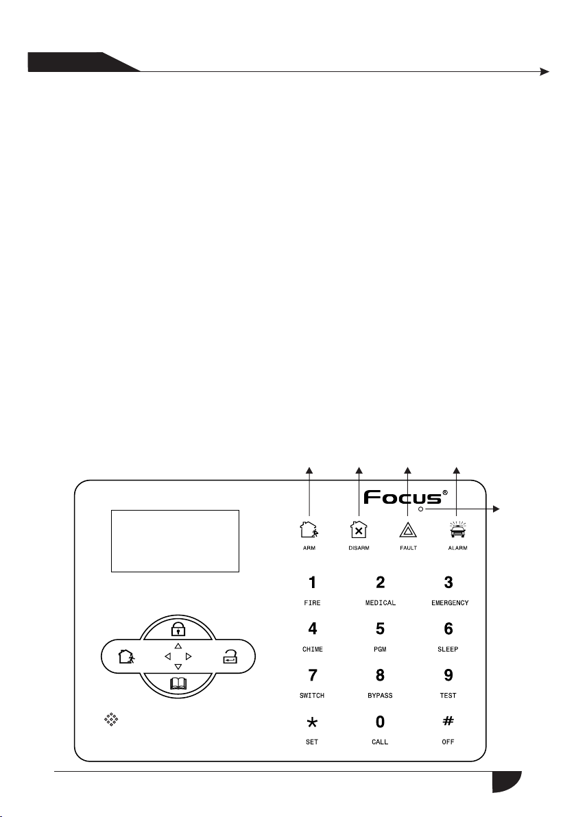
3.1 About panel
Disarm Alarm
Arm
Fault
150m
Intercom/monitor hole
LCD screen
/re turn button
Pro tection
A light hole
Sta y/on turn key
Eve nt query
/un der turn key
Key machine
Set the
key s
Enter
key
5

Us er ma nual
产品手 册
Arm led: Light on under armed status, Light flashes under stay status.
Disarm led: Light on under disarmed status
Tro uble led: Light on when with zone trouble. Light flashes when AC cut.
Alarm led: Light flashes when alarm.
1
1
1
2
1
3
1
4
1
5
1
6
7
1
8
1
9
1
10
:Press 3 s econds to tirgger fire alarm
:Press 3 s econds for medical help
:Press 3 s econds for SOS
:Press 3 s econds then enter user code to enable or disable delay
zone do orbell(Refer to page 36)
:Press 3 seconds then enter user code to enable or disable PGM
outpu t(refer to page 30)
:Press 3 s econds to enter or exit sleep mode.
:Press 3 seconds then enter user code to enable or disable
eletr ical switch.
:Press 3 seconds then enter user code to bypass zones or
activ ate zones.
:Press 3 seconds then enter user code to proceed normal testing,
siren t esting and walk testing.
:Press 3 seconds to make phone call through GSM, the longest
talk ti me is 240 seconds. the call will be interrupted when alarm
occur s.
Sleep m ode: all led indicators, backlight, voice, remind tone will be disabled
under sleep mode, The pan el will exit s leep mode au tomatica lly when users
enter system setting or when alarm occurs.
Bypas s zone: bypassed zones means zones disabled. The byp ass will be
restored when users disarm systems under home armed or armed status.
Communication test: To test the communication between the panel and the
CMS if no rmal
Siren test: to test if siren working normal
Wal k test: to tes t if the detec tors are working normally with the panel and alarm
6
Us er ma nual
产品手 册
3.2 Basic operation
Facto ry default
Adminitrator password: 012345
16 User passwords, NO. 01 factory default is 1234. No. 02-16 of the user
password is blank and can not enter the user setting untill user set the
password.
Disarm: User password[1234]+DISARM
Home arm: Home arm key
Arm: Arm key
Event log: inquiry key
Shutdown operation: AC power-off state ( press and hold for more than 3
secon ds) + user pas sword [123 4]+
Enter system setting: press and hold for more than 3 seconds+
admin strator pa ssword [01 2345]+
Enter user setting: Press and hold for more than 3 seconds+ user NO.
(01) +u ser passwo rd(1234) +
Zone inspection: Not insepct wired zones within one minutes of panel
power up
Password reset: Enter 000000 to enter system setting menu within one
minute of panel power up.
#
#
*
#
*
#
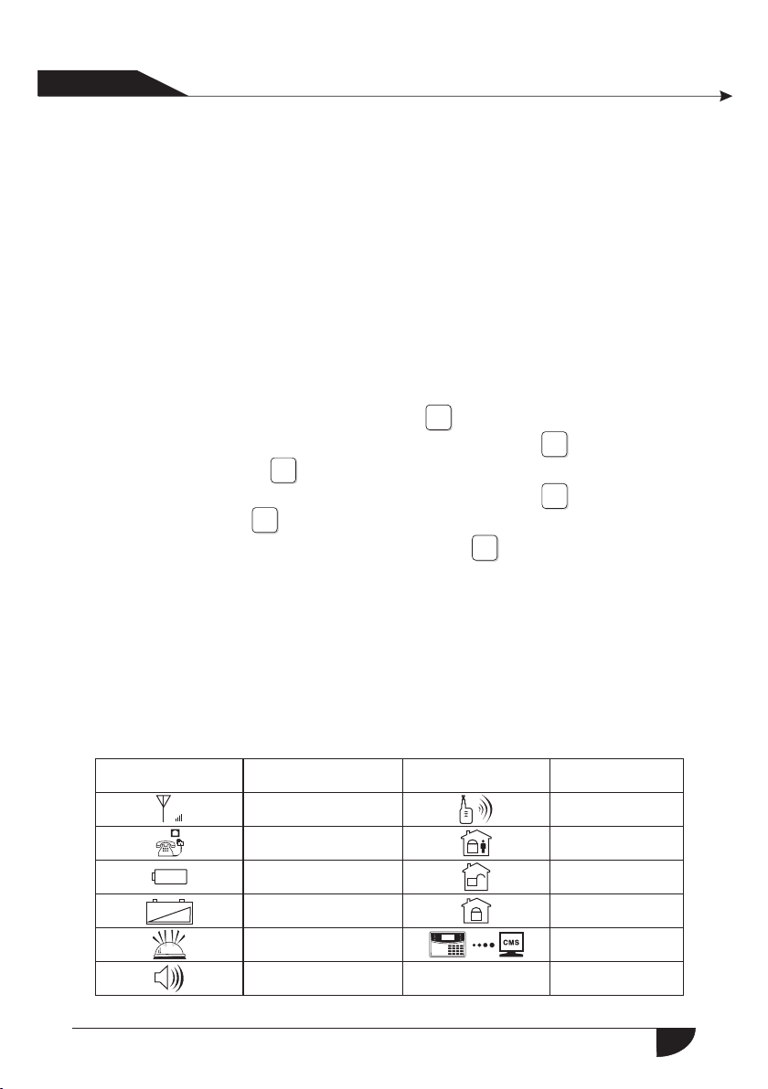
3.3 Flashes when phone line cut. Light on when phone line
is normal.
Icon
G
+
Meaning
GSM signal strength
Telephone
_
Detector low battery
PANEL b attery
Voice prompts
line
low
Alarm
Icon
Meaning
GSM is enabled
Left behind
Disarm
Arm
Enable GPRS
7
Us er ma nual
产品手 册
Flashes when phone line cut. Light on when phone line is normal.
Flashes when GSM not ready, Light on when GSM is normal.
Flashes under sleep mode. Light on uder normal working mode.
Flashes when GPRS disconnected with CMS. Light on when GPRS is
connected well with CMS.
Zone 5 alarm
Zone 5 tr ouble
Zone 5 detector lost
Zone 5 low battery
Zone 5 bypass
The alarm zone number will still be displayed on LCD screen after fir st disarm
when alarm accurs, returned to normal screen display only users disarm twice.
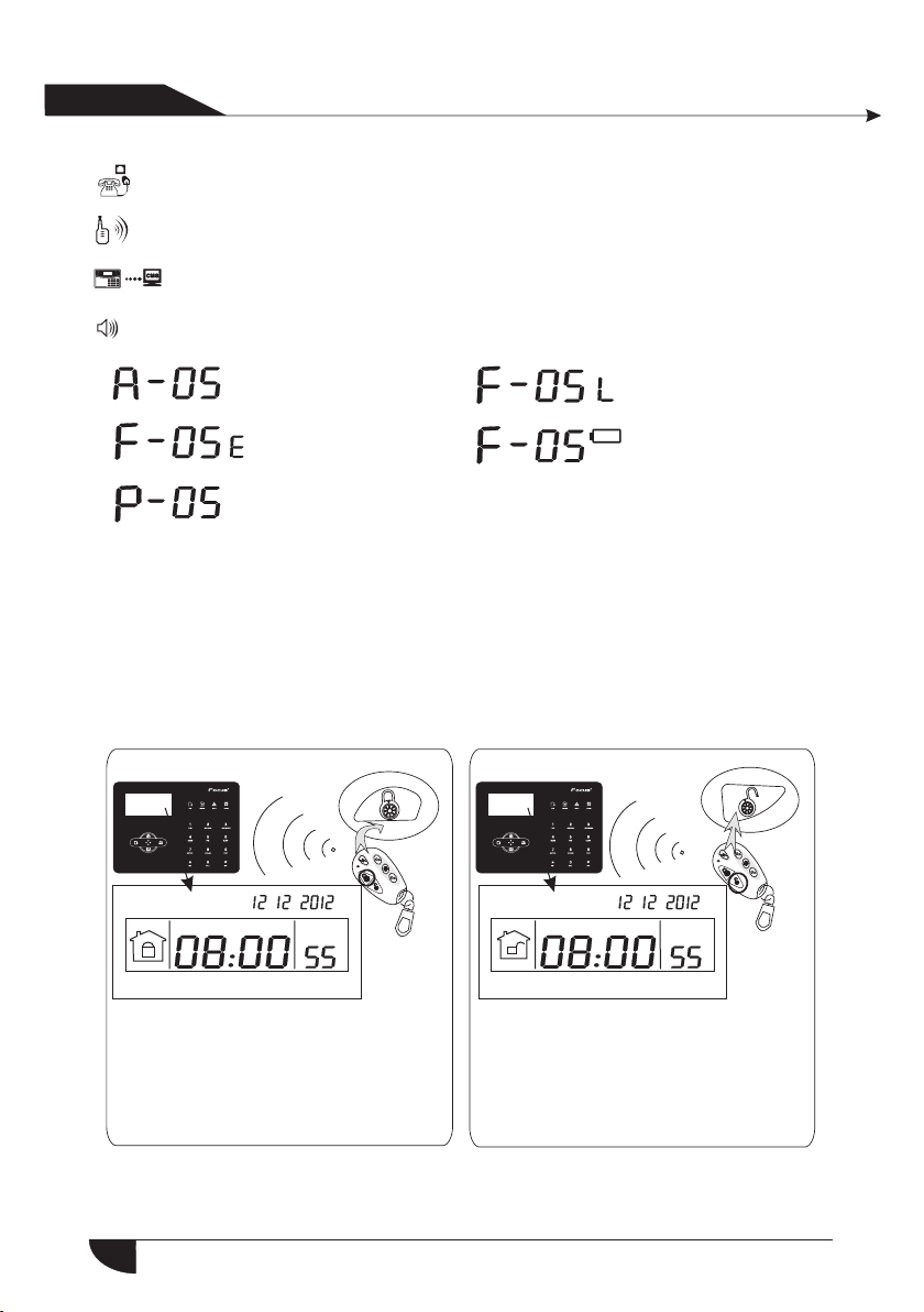
3.4 Host arm and disarm
☆ Arm
~DI~DI~ ~DI~DI~
YDM YDM
Press the key for arm away on remote
or the keypad,then you hear"system
armed,please exit the protection area"
there will be “Dee-dee”sound to
confirm the system is armed
successfully.
☆ Disarm
Press the disarm key on the remote or
enter your user password on the
keypad,then you will hear"dee"and
voice"system disarmed",then you have
disarm successfully.
8
Us er ma nual
产品手 册
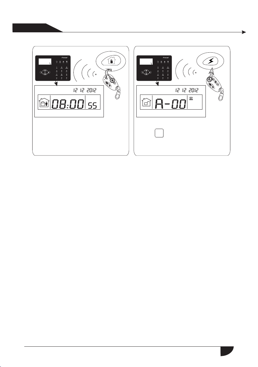
☆ Home Arm
☆ Panic
~DI~DI~ ~DI~DI~
YDM YDM
Press the key for home arm on the
remote or "HOME"key on the keypad,
then you will hear "s ystem stay"
And it display home arm icon on the
LCD screen.
Press the panic button on remoter,or
press" "key on panel for 3
seconds.
3
The codes of arm/disarm via different ways:
Arm/disarm via keyfobs: 1-8 keyfobs----#40-47
Arm/disarm via user codes: 1-16 user codes---#01-16
Arm/disarm via phone call: 1-4 user phone number---#60-63
Arm/disarm via CMS: #97
Arm/disarm via home arm key or arm key in panel: #98
Auto arm/dsiarm via auto timer or key zone: #99
9

Us er ma nual
产品手 册
3.5 Alarm procedure
Tele
1st
Alarm software
CMS
110 alarm center
2.The panel use Ademco Contact ID to send
alarm information to alarming center.
If the panel got confirmation from center,
then alarm successfully.Otherwise, the panel
will repeat alarm.The alarm information will
be display and reslove by the alarm center computer
software.
Telephone t ele pho ne Cell phone
2nd
3.The panel will dial 1-4 telephone numbers
as preset.If more than 4 numbers,the panel will
start with second telephone number, then 3,4...
Alarm situation found,
start to send message
3rd
4th
d
e
r
Wi
1.The detector activated
send alarm infor
mation to alarming
center.
Wir
e
les
s
10

Us er ma nual
产品手 册
Chapter IV Voice alarm receiving
and GSM control
4.1 Remote phone control
User ca n remote con trol the system by phone call, after the preset ringing
times then panel will off hook the phone then enter the 4 digit user codes
according to voice prompting and operate as per the voice prompting.
1 2 3
User call lan dline
phones
111
Then ent er us er code acc ord ing
to voice p rom pting( th e fac tory
defaul t use r code is 123 4)
1 1
3
2
4
Tele phon e line
The phon e rin gs is 7
times, a fte r 7 times rin g,
the pane l wil l off- hoo k
automa tic ally.
4
Please e nte r
password
Press 1 to arm sy stem
Press 2 to disa rm system
Press 3 to Stay a rm
Press 4 to chec k system statu s
Press 5 to appl iance switch c ontrol
Press 6 to cont rol programm able
output port
Press 0 to Disc onnect
5
4.2 Alarm receiving phone operation
When al ram, the pan el will dial the pre-set voice phone number, when the
user pick up the call, they will hear the voice prompting as below, if not press 1
to cancel the alarm or press 4 to disarm the system, after off-hook, the panel
will call other preset voice phone numbers .
The pane l wil l dial
the pres et vo ice
phone nu mbe r
when ala rm oc curs
1 2
The user p ick u p
the call
Play the r eco rded voic e mes sage
first, then :
Press 1 to canc el alarm
Press 2 to chec k alarm eve nt
Press 3 to arm sy stem
Press 4 to disa rm system
Press 5 to Stay a rm
Press 6 to enab le siren
Press 7 to list en-in
Press 8 to cont rol programm able
output port
Press 0 to Disc onnect
3
11

Us er ma nual
产品手 册
4.3 GSM remote operation ( talk-back function added)
When al arm occurs , GSM will call the preset voice number, when pick up
the cal l,enter 4 digit user code, then voice prompt: Press 1 to arm system,
Press 2 t o disarm system, Press 3 to Stay arm, Press 4 to check system
statu s, Press 5 to ap pliance switch control, Press 9 to talk-back, Press 0 to
Disco nnect.
4.4 GSM alarm receiving (talk-back function added)
When al arm occurs, it will send SMS first, then call the preset voice number,
when pick up the call, it will play the recorded voice message first, then voice
promp t: Press1 to cancel alarm, Press 2 to check alarm event, Press 3 to arm
syste m,Press 4 to disarm system, Press 5 to Stay arm, Press 6 to enable siren,
Press 7 t o listen-in, Press 8 to con trol programmable output port, Press 9 to
talk-back, Press 0 to Disconnect.
4.5 GSM control via SMS
Arm command: password:1234 system arm
Disamr command: password:1234 system disarm
Stay co mmand: password:1234 system home
Cancel alarm command: password:1234 system cancel
Statu s checking command: password:1234 system status
Enable programmable output port command: pasword:1234 pgm open
Disable programmable output port command: password:1234 pgm clos e
Enable appliance switch command:
password:1234 switch open X(X=1-8 on behalf of appliance switch numb er)
Disable appliance switch command:
password:1234 switch close X(X=1-8 on behalf of appliance switch num ber)
Set apn:
Set ID:
Set password:
Note: the factory default user code is 1234, when arm successfully, SMS auto
reply”a rm success fully”, if the password is correct, the command is not
corre ct, SMS will r eply” operation failure”, if the password is not correct,
no SMS re ply.
password:1234 apn: aaa
password:1234 user: bbb
password:1234 pwd: ccc
" "
" "
" "
12

Us er ma nual
产品手 册
Chapter IV Voice alarm receiving
and GSM control
Press[*] for 3 seconds
+
1
*
3
2
+
#
4
Set sys tem clock
1
Set user password
2
Set voice phone
3
5.1 Set system clock
For exa mple: set system clock as : 22:59:36 22/12/2012
Press[*] for 3 seconds
*
Please enter system
clock, pressconfirm
key tosave,press
back key toexit.
+ + +
According to flash of Y.M.D.H.Min.Sec on screen, enter 12.12.22.22.59.36
by turn, also can press [UP] [DOWN] key to move cursor.
5
9
Min
Enter passord
3 6
Sec on screen
+
1 2
+
#
+ + +
2 1 2 2 2 2 2
1
Y M D H
+ +
3
4 1
##
5.2 Set user password
For exa mple: Set No.16 user pasword as 5678
Press[*] for 3 seconds
*
Please enter the serial number
of your modified password,
confirm key to confirm,press
back key to exit.
Enter passord
1
+ + +
4
#
+
+
6
1
#
3
2
#
2
Enter password, press
confirm key to save,
press back key to exit.
+
5
6
Note: Can set 16 user passwords, corresponding password No. from 01 to 16,
Only No .1 passwor d can enter user setting.
+
7
8
#
5.3 Set voice phone (refer to page 15)
13

Us er ma nual
产品手 册
Press[*] for 3 seconds
+ +
*
6.1 Set password
Press[*] for 3 seconds
+ + +
0
*
Chapter VI System Setting
Set password
1
2
Set CMS number
3
Set voice phone
4
5
1
0
1
3
2
2
4
3
5
4
#
1
#
Set password
Set system options
5
Set wireless devices
6
Set zone
7
System maintenance
8
Set GSM
Set advanced options
9
#
Then operate according to the
voice prompt as below.
[1]Set A dmi n password
1
Enter password,
press confirm key to save,
press back key to exit.
#
X
X
X
The setting is saved
Note: 1. password setting include “us er pa ssw ord” a nd “ ad ministrator password”,
Note: 1. password setting include “us er pa ssw ord” a nd “ ad ministrator password”,
Note: 1. password setting include “us er pa ssw ord” a nd “ ad ministrator password”,
Note: 1. password setting include “us er pa ssw ord” a nd “ ad ministrator password”,
Note: 1. password setting include “us er pa ssw ord” a nd “ ad ministrator password”
user password mainly use to disar m the s yst em, i t is a pr iva te key for remote
user password mainly use to disar m the s yst em, i t is a pr iva te key for remote
user password mainly use to disar m the s yst em, i t is a pr iva te key for remote
user password mainly use to disar m the s yst em, i t is a pr iva te key for remote
user password mainly use to disar m the s yst em, i t is a pr iva te key for remote
controlling, “administrator pas swo rd” is t he so le pa ssword to set the system.
controlling, “administrator pas swo rd” is t he so le pa ssword to set the system.
controlling, “administrator pas swo rd” is t he so le pa ssword to set the system.
controlling, “administrator pas swo rd” is t he so le pa ssword to set the system.
controlling, “administrator pas swo rd” is t he so le pa ssword to set the system.
Please enter the serial number
of your modified password, confirm
key to confirm, press back key to
exit press confirm key to save,
[2]Set user password
2
##
X X X
Enter password,press
confrim key to save,
Press back key to exit
X X X
The setting is saved
#
#
14

Us er ma nual
产品手 册
2.Administrator password is 6 d igi t, us er pa ssw ord is 4 digit, can set 16 user passwords,
corresponding password No. fr om 01 t o 16, b ut No .2- 16 password can’t enter user
setting.
3.If forgot the password, when the alarm is powered on, for the first minute,th e
administrator password is 000 000 .
For example: Set admin pasword as 8888 88
Press[*] for 3 seconds
*
Note: 1.Above base on the correct oper ati on, i f inc orr ect operation occurs, please
press back key to back previous menu to re set .
2.The factory default of admin passw ord i s 987 6, us er pa ssword is 1234, if you
have modified the password, please r efe r to th e new p ass word.
Enter password
Enter password,press
confirm key to save, press
back key to exit
+ + + +
0
+
3
21
8 8 8 8
5
4
8 8
1
#
#
+
#
6.2 Set CMS number
Press[*] for 3 seconds
+ + +
1
0
*
3
2
5
4
#
Se t CMS
Then operate according to the voice
#
2
prompt as below:
1
#
[1 ] Set C MS
ph one n umber
#
1
Please e nte r phone
number, p res s * key to
delete , Lon g press 1,
dialin g pau se 1
second ,pr ess confi rm
key to sav e, pr ess
back key t o exi t.
The sett ing
is saved
2
XX
X
[2] Set CM S
phone no .2
#
Please e nte r
accoun t No. p ress
confir m key t o
save, pr ess b ack
key to exi t
#
Please e nte r
dialin g tim es,
press co nfi rm key
to save, p res s
back key t o exi t
#
[4] Set CM S
dialin g tim es
4
X
X XX
The sett ing
is saved
[3] Set
User Num ber
# # #
3
XX
X X
The sett ing
is saved
[5] Set CM S
commun ica tion
test int erv al time
5
Please e nte r
commun ica tion
inspec tio n interva l
time, 0 fo r dis able,
press co nfi rm key
to save, p res s back
key to exi t
#
X
The sett ing
is saved
15
#

Us er ma nual
产品手 册
Note: 1.The user code is the identification code in CMS setting, CMS 1 and CMS
2 use the s ame user cod e; dialing times can be set 1-15 , communication
inspe ction inte rval time can be set 0-999 hours, the common setting is
24 hour s.
2.Whe n set phone nu mber, long press 1, display the letter P, means p ause
1 secon d when dialing, when the telephone line which connect to the
alarm p anel is sub- line, need a pause dialing.
3.For G SM, just rec ognize the n umber behind P, can make sure telephone
and GSM d ial the same n umber.
For example: the sub-line connect to alarm panel, CMS number is 80808080 ,
in this w ay, se t CMS number l ike this 9P80808080, 9 is out code.
Press[*] for 3 seconds
*
Enter password
Please enter phone number,
press * key to delete, Long
press 1, dialing pause 1
second, press confirm key to
save, press back key to exit.
+ + +
1
0
3
2
+
1 8
9
Press[1] key for 3 seconds.
5
4 1
0
#
2
8
8
0
+
#
8
0
6.3 Set voice phone
Press[*] for 3 seconds
+ + +
1
0
*
3
2
5
4
#
Set voice phone
#
3
Then operate according to
the voi ce prompt as below:
[5] Set vo ice p hone dial ing times
#
+
#
0
[1] Set
voice ph one 1
1
#
16
[2] Set
voice ph one 2
2
Please e nte r phone
number, p res s * key to dele te,
Long pre ss 1, d ialing pa use 1
second , pre ss confir m key to
save, pr ess b ack key to ex it.
XX
The sett ing
is saved
[3] Set
voice ph one 3
#
X XX
3
#
[4] Set
voice ph one 4
#
4
Please e nte r dialing
times, p res s confirm
key to sav e, pr ess back
key to exi t.
5
#
X XX
The sett ing
is saved
[5] Set
voice ph one
dialin g tim es
#
#
[6] Set vo ice
phone pa ssw ord
inspec tio n
#
6
1.Enabl e
2.Disa ble
#
X
The sett ing
is saved

Us er ma nual
产品手 册
Note:1.dialing times can set 1-15
2.When p anel call user’s phone, if you enable password check, it will
promp t enter user p assword when pick up the call.
For example: Set voice phone No.3 is 12345678
Press[*] for 3 seconds
*
Enter password
Please enter phone number,
press * key to delete, Long
press 1, dialing pause 1 se
cond, press confirm key to
save, press back key to exit.
+ + +
3210 54
+
1
32
#
4
5
#
3
6
7
8
6.4 Set system options
Set system clock
1
Set entry delay
2
Set exit delay
Press[*] for 3 seconds
+ + +
1
0
*
6.4.1 Set system clock
For example: Set system time to 22:59:36 22/12/2012
Press[*] for 3 seconds
*
Enter password
Please enter system
clock, press confirm
key to save, press
back key to exit.
3
2
5
4
+ + +
0
+
1
Y M D H Mi n
4
#
1
2
#
3
2
+ + +
4
1
2 2 2 2 2
3
Set siren time
4
Set ring times
5
Set detector loss inspection
6
Set arm/disarm tone
7
Set arm/disarm report
8
Set others
9
+
5
+
4
#
#
+
#
3
+
#
1
#
5
9
+ +
According to flash of Y.M.D.H.Min.Sec on screen, enter 12.12.22.22.59.36
by turn, also can press [UP] [DOWN] key to move cursor.
6
3
Sec on screen
#
17

Us er ma nual
产品手 册
6.4.2 Set entry delay
When trigger alarm, the panel will give delay alarm time(default setti ng is 10s)
For example: Set entry delay to 20seconds
Press[*] for 3 seconds
*
Enter 3 digit number from 0-255, add 0 if less than 3 digit.
Note: Entry delay is just effective for delay zone. Other zone types can’t
enter d elay.
6.4.3 Set exit delay
After user armed the system, it is convenient for user to exit the area after
arm successfully.( the default setting is 10seconds)
For example: Set exit delay time is 20s
Press[*] for 3 seconds
*
Enter 3 digit number from 0-255, add 0 if less than 3 digit.
Enter password
Please enter entry
delay time, press
confirm key to save,
press back key to exit
Enter password
Please enter exit
delay time, press
confirm key to save,
press back key to exit
0
+
0
1
0
+
3
21
+
0
2
3
2
0
4
0
2
+ ++ +
5
4
#
#
4
#
+ ++ +
5
#
+
#
#
4
#
2
#
3
6.4.4 Set siren time : The siren ri ng time afte r alarm is tri ggered( th e default
setti ng is 5 minute s)
For example: Set siren time is 10 minutes
Press[*] for 3 seconds
*
6.4.5 Set ring times
User remote control alarm panel, dail the preset phone number, the panel wi ll
off-hook after phone ring times( the default setting is 7 times)
For exa mple: Set ring times is 5
Enter password
Please enter 0 to 30
minutes siren time, press
confirm key to save, press
back key to exit
+
1
0
3
2
+
1
5
4
+
#
0
+ ++
#
#
4
#
4
18

Us er ma nual
产品手 册
Press[*] for 3 seconds
*
Enter 2 digit number from 0-15, add 0 if lower than 10.
Note: The max . Ring times a s per the loca l communic ation, if se t 0, not
off-hook .
6.4.6 Set detector loss inspection
The alarm panel will inspect the detectors’ status or alarm info in this time
inter val, if not receive, it is determined that the detector is loss, the general
setti ng is not less than 6 hours( the default setting is 0, disable this function)
For example: Set detector loss inspection time is 8 hours.
Press[*] for 3 seconds
*
6.4.7 Set arm/disarm tone
When user arm/disarm the system through remote control, if siren will sound
or not fo r prompting.( the default setting is disabled)
For example: Set siren with short sound when arm/disarm through remote control.
Enter password
Enter password.... Please enter ring
times, if set as 0, the phone will not
off hook, press confirm key to save,
press back key to exit
Enter password
Please enter 0 to 99 hours detector
loss inspection time, 0 for disable,
press confirm key to save, press
back key to exit
+
0
+ + + +
0
3
21
3
21
5
4
+
0
5
4
+
0
+ ++
#
4
+
5
#
4
#
+
#
8
5
#
#
#
6
#
Press[*] for 3 seconds
*
Enter password
Please choose arm/
tone: 1. siren short sound
2. no voice, press confirm
key to sa ve, press back key
to exit
+ + ++
1
0
disarm
3
2
5
4
+
+
1
#
#
4
#
7
#
19

Us er ma nual
产品手 册
6.4.8 Set arm/disarm report
Set if ar m/disarm r eport to CMS o r not( the default setting is disabled)
For example: Set arm/disarm report to CMS
Press[*] for 3 seconds
*
Enter password
Please choose arm/disarm
report: 1. enable, 2. disable,
press confirm key to save,
press back key to exit
+ + +
0
1
3
+ +
1
+
5
42
#
4
#
6.4.9 Set others
Set emergency alarm
1
siren type
Set A C off i nsp ect ion t ime
2
Enable magnetic contact
3
inspection
Check wireless detector
4
+ + ++
0
*
31
2
5
4
#
#
4
#
9
tamper
Set force arm
5
Set telephone line
6
disconnect remind
Set zone alarm times
7
Set listen-in time
8
Set A C off r emi nd
9
#
#
8
6.4.9.1 Set emergency alarm siren type( the default setting is mute)
For example: set emergency alarm siren type is pedal point.
Press[*] for 3 seconds
*
+
Enter password
#
1
Please choose zone siren
type: 1.pedal point 2.pulse
tone 3. mute, press
confirm key to save, press
back key to exit
+
1
0
3
2
5
4
+
+
1
+ +
#
+
#
#
4
9
20
#

Us er ma nual
产品手 册
6.4.9.2 Ac off inspection time setting. When the AC power is off, delay to report
to CMS( factory de fault dela y time is 30 min)
Example:set AC off inspection time as 15 min
Press[*] for 3 seconds
*
Enter password
+ + +
1
0
3
2
+
5
4
#
#
4
#
9
0
255 minutes
1
2
1
2
3
3
5
4
magnetic
5
4
5
1
0
+
#
1
#
#
#
4
#
9
#
#
4
#
9
Plsease enter 0 to
+ + +
#
2
6.4.9.3 Magnetic contact inspection: Set if the alarm panel show zone trouble
on LCD sc reen or not wh en sperate the magnetic strip from transmitter.
(Fact ory defaul t disable th e inspection)
Examp le: enbale the magnetic contact inspection
Press[*] for 3 seconds
*
+ + +
6.4.9.4 Check wireless detector tamper: if the enable the checking when
trigg er the detec tor’s tamper , w ill trigger alarm. If disable the
check ing, it will n ot trigger alarm.(factory default enable the checking)
Example: disable the checking of wireless detector tamper.
Press[*] for 3 seconds
*
Enter password
#
3
Enter password
AC off duration time.press
confirm key to save, press
back key to exit.
+ + +
Please choose: 1. Enable
contact inspection 2. Disable
Press confirm key to save,
Pressback key to exit.
+ + + +
0
Please choose : 1. Enable
#
4
6.4.9.5 Set force arm: if enabel set force arm, when there is zone trouble, the
syste m can be armed a nd report th e trouble zone’s bypass message
to CMS. I f disable th e force arm, t he system ca n not be armed(factory
defau lt is disabl e forem arm)
Example: enabel force arm
detector tamper inspection, 2. Disable
Press confirm key to save,
Pressback key to exit.
wireless
+ ++
#
2
21

Us er ma nual
产品手 册
Press[*] for 3 seconds
*
Enter password
+ + + +
1
0
3
2
5
4
#
#
4
#
9
Please choose: 1. Auto force
+ + +
5
#
6.4.9.6 Set telehpone line disconnect remind(factory default del ayed
siren sou nd remind)
Example : disable telephone line disconnet remind
Press[*] for 3 seconds
*
+ +
6.4.9.7 set zone alrm times: if set the alarm alarm times as 1, when
zone star t alarm but the zone is trigger one time again, the panel
will not ma ke alarm.
Example: set zone alarm times as 1 time
Press[*] for 3 seconds
*
7
Enter password
6
#
Press confirm key to save,
Pressback key to exit.
Enter password
#
Press confirm key to save,
Pressback key to exit.
2. Forbid force arm via remote
control.
Press confirm key to save,
pressback key to exit.
+
1
0
Please choose telephone
line disconnect remind:
1. Siren delay remind,
2. Buzzer remind, 3 disable
+ + +
0
Please choose zone alarm times:
1. no limited 2. 1 time
2
1
2
arm
#
1
+ + +
5
+
3
+
5
+ +
2
#
4
9
#
#
#
#
4
9
#
#
#
3
4
3
4
6.4.9.8 set listen-in time(factory default 10 sec)
Example: set listen-in time as 20sec
Press[*] for 3 seconds
*
+
Enter password
Please enter 10 to 255
#
8
Press confirm key to save,
Pressback key to exit.
seconds listen-in time
+ + +
1
0
3
2
5
4
+ +
0
22
+
#
0
2
#
4
#
9
#

Us er ma nual
产品手 册
6.4.9.9 Set AC off remind(factory default remind by SMS)
Example:d isable AC off remind
Press[*] for 3 seconds
*
Enter password
+ + +
#
9
Press confirm key to save,
Pressback key to exit.
+ + + +
0
Please choose AC off remind:
1. SMS remind 2. Voice phone
remind 3. Disable
3
21
5
4
#
3
6.5 manage wireless device
Set remote control
Press[*] for 3 seconds
+ ++
5
1
*
6.5.1 set remote control
Press[*] for 3 seconds
*
6.5.1.1 enroll remote control
Example: enroll remote to the #3 remote in alarm panel
Press[*] for 3 seconds
+ + +
0
+
1
0
*
1
Enter password
#
Press confirm key to save,
Pressback key to exit.
3
2
2
Please enter the serial
number of remote control
4
3
5
4
#
+ +
#
+ + + +
0
5
#
+
5
1
2
1
#
3
4
3
1
Set detectors
2
Set appliance switch
3
Enroll wireless siren
4
5
Set door bell
#
5
#
#
Pressback key to exit.
4
9
#
#
#
Enroll remote control
1
Enter remote control code
2
3
Delete remote control
5
Please trigger the
remote control
1
#
#
Enroll successful
Tri gger arming key on the remote control
+
#
23

Us er ma nual
产品手 册
6.5.1.2enter remote control code
Example: manaul enter the address code of remote 112113114 to the #8
remot e in alarm pa
Press[*] for 3 seconds
*
Enter password
+ + +
1
0
3
2
+
5
4
#
5
#
#
1
Please enter the number
+ + +
#
2
Press confirm key to save,
Pressback key to exit.
Please enter remote
Press confirm key to save,
Pressback key to exit.
6.5.1.3 delte remote control
Example: delete the # 5 remote
control Number
Press[*] for 3 seconds
*
+
#
3
6.5.2 set detector
Press[*] for 3 seconds
1
0
*
of remote control.
Enter password
Please enter the serial number of remote
Press confirm key to save,
Pressback key to exit.
control to delete, enter 0 to delete all.
3
2
5
4
serial
#
8
+
11 11 13 41
2
+ + + +
0
3
21
5
4
#
+ +
1
+ ++ +
5
#
#
#
2
2
3
6.5.2.1 detector coding
Example: auto code detector to # 9 detector in alarm panel
Press[*] for 3 seconds
*
+
1
Enter password
Please enter
#
Press confirm key to save,
Pressback key to exit.
detector Number
+ + +
1
0
3
2
+
0
+
5
4
9
#
+
#
Pressback key to exit.
+
#
5
5
Detector coding
Enter detector code
Delete detector
5
Please trigger the
detector
1
#
#
#
#
#
2
24
trigger the detector
Enroll successful
+
#

Us er ma nual
产品手 册
6.5.2.2 enter detector code
Example: manual enter the address code of detector 011022033 to
the # 7 detec tor in alarm panel
Press[*] for 3 seconds
*
2
Press confirm key to save,
Pressback key to exit.
6.5.2.3 delete detector
Example: delete the # 3 detector
Press[*] for 3 seconds
*
+ + +
Enter password
P l e a s e e n t e r
detector Number.
++
#
Press confirm key to save,
Pressback key to exit.
Please enter detector code
Enter password
Please enter the serial number of
#
3
detector to delete, enter 00 to delete all.
Press confirm key to save,
Pressback key to exit.
+ + +
1
0
+ + +
1
0
3
2
+
0
+
0
3
2
+
5
4
+
#
7
11
+
5
4
5
#
00
22
5
#
3
0
#
3 3
#
#
2
+
#
#
2
#
6.5.3 set appliance switch
Press[*] for 3 seconds
+ + ++
0
*
6.5.3.1 enroll appliance switch
Example: auto the appliance to the # 1swith in alarm panel
Press[*] for 3 seconds
*
+ + +
#
1
Press confirm key to save,
Pressback key to exit.
3
21
Enter password
Please enter the serial
number of appliance switch
Tri gge r app lia nce
switch
5
4
+ + +
5
#
1
0
Enroll successful
#
2
#
3
+
3
1
5
4
#
Pressback key to exit.
+
Enroll appliance switch
1
Delete appliance switch
2
#
Please trigger
appliance switch
#
5
#
#
3
25

Us er ma nual
产品手 册
6.5.3.2 Delete appliance switch
Ex ample: delete the # 4 applian ce switch
Press[*] for 3 seconds
*
+ + +
Enter password
Please enter the serial number of appliance
switch to delete, enter 0 to delete all
#
2
Press confirm key to save,
Pressback key to exit.
+
0
6.5.4 Enroll wireless siren
+ + ++
1
0
*
6.5.4.1 Enroll wireless siren
Press[*] for 3 seconds
*
3
2
Enter password
5
4
#
+ + + +
0
+ + +
1
1
3
2
5
#
3
2
5
4
#
4
5
4
5
#
#
4
Enroll wireless siren
1
Delete wireless siren
2
5
#
#
#
3
#
#
4
Please make wireless siren
+ +
#
1
Start siren co din g, please
Pressback key to exit.
operate as voice prompting
NOTE: when dual-way wireless siren make tamper alarming, the LCD scree n
of alar m panel will d isplay zone 41 alarming.
6.5.4.2 Delete wireless siren
按 3秒以 上[*]
*
+
2
Note: It is dual-way wireless siren deleted.
under coding status, then press
confirm key to start coding.
Press confirm key to save,
Pressback key to exit.
Press confirm key to save,
Pressback key to exit.
Enter password
Press confirm key to save,
#
Pressback key to exit.
+
1
0
Delete wireless siren
2
This is one way wireless siren
This is 2-way wireless siren
3
Make wireless siren
under coding status
+ + +
5
4
+
#
#
+
5
#
26
#
#
#
4

Us er ma nual
产品手 册
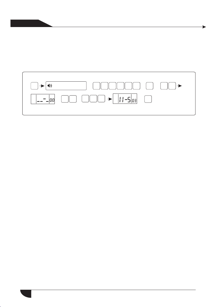
6.6.5 Set door bell
+ + ++
1
0
*
6.5.5.1Enroll doorbell
Press[*] for 3 seconds
*
Enter password
Enroll doorbell
3
2
5
4
+ + +
0
5
#
1
3
2
5
#
4
#
+
5
#
1
Delete doorbell
2
5
#
5
#
+ +
Note: can only learn a wireless doorbell, the trigger will be issued after t he chink
Press[*] for 3 seconds
# #
1
Pressback key to exit.
6.5.5.2 Delete doorbell
*
+
# #
2
Please trigger doorbell
Enter password
Delete doorbell
Press confirm key to save,
Pressback key to exit.
+ + ++
1
0
2
Please trigger
doorbell
+
3
5
4
+
#
Enroll
successful
5
#
5
#
6.6 Sector Settings
Set zone attribution
1
Press[*] for 3 seconds
++ +
1
0
*
6.6.1 set zone attribution
The type of zone attributuion is as below:
0)disable zone 1> de lay zone 2> pe rimeter zo ne
3>inerior zone 4> emergency zone 5> 24 hours zone
6>fire zone 7> key zo ne
1.Zone attribution is the alarm type of the zone display on the alarm panel
s LCD scr een when the zone is triggered. When set the zone attribution as
0 is to dis able the zone. The alarm panel will not make alarm when trigge r
this zo ne.
3
2
5
4
6
#
#
Set zone siren type
2
Set wired zone loop type
3
Set wired zone response speed
4
Set related zone
5
’
27

Us er ma nual
产品手 册
2.interior zone only trigger alarm when the zone is triggered under syste m at
armed status.
3.delay and perimeter zone trigger alarm when the zone is triggered under
syste m at armed or home arm status.
4.emergency zone, 24 hours zone, fire zone will trigger alarm when system
at any st atus
5.wirelss zone can not set key zone type. When wired zone is set as keyzone,
trigg er the zone, system turn to disarm status. The zone restore, system turn
to arme d status. This is for access contron system.
Example: set zone 39 as keyzone type
Press[*] for 3 seconds
*
Enter password
+ + +
1
0
3
2
+
5
4
6
#
#
#
1
Press confirm key to save,
Pressback key to exit.
0. Disable the zone 1. Delay zone 2. Perimeter zone 3. Interior zone
4. Emergency zone 5. 24 hours zone 6. Fire zone 7. Key zone
6.6.2 set zone siren type(factory default is pefal point)
Example set zone 23’s siren type as pulse tone
Press[*] for 3 seconds
Press confirm key to save,
Pressback key to exit.
+ +
6.6.3 set wired zone loop type(factory default EOL )
The options is as below:
1>EOL loop type: when the resistor value is 10k on the zone is normal, when
the zon e is open loop or shortcut trigger alarm
2>N/C loop type: zone shortcut is normal, open loop trigger alarm
3>N/O loop type: zone open loop is normal, shortcut loop trigger alarm
Please enter the zone No. to modify.
Please choose zone type:
*
2
Enter password
Please enter the zone
number to modify.
#
0
+ +
3
2
+ +
3
3
21
#
5
4
Please choose zone siren type:
1.pedal point 2.pulse tone 3. Mute
Press confirm key to save,
Pressback key to exit.
#
9
++ + +
6
#
+ +
#
7
2
#
#
28

Us er ma nual
产品手 册
10KΩ
EOL lo op
N/C wiring diagram
Example: set zone 35 as N/O loop type
Press[*] for 3 seconds
*
Please enter the zone
Press confirm key to save,
Pressback key to exit.
number to modify
+ +
#
3
NC
Enter password
Z
C
+ + +
0
+ +
3
NO
3
21
5
#
10KΩ
EOL lo op
N/O wiring diagram
+
5
4
Press confirm key to save,
Pressback key to exit.
#
Please choose loop type:
1.EOL 2. N/C , 3.N /O
Z
C
6
#
3
6.6.4 set wired zone response speed(factory default is 500 milliseco nd)
Press[*] for 3 seconds
*
Press confirm key to save,
Pressback key to exit.
+ +
Enter password
Please enter the zone
numbEr to modify
#
2
+ + +
1
0
+ +
3
2
4
4
#
0
Press confirm key to save,
Pressback key to exit.
+
5
Please choose loop
response speed: 1. 500ms,
2. 10ms
6
#
#
4
#
#
Note: Normall the detector’s response speed is 500 millisecond, high spe ed
respo nse detect or like vibration detector is 10 millisecond
6.6.5 set related zone: zone 1+zone 2+related time+mode
The options as belows
0>disable related zone mode
1>EXIT- ENTRANCE dual trigger mode: trigger zone 1 or 2 seperately will
not tri gger alarming. Trigger zone 1 first, then during the period of related
time tr igger zone 2, then both zone 1 and 2 trigger alarm.Trigger zone 2
first , then trigg er zone 1 will not trigger alarm.
29

Us er ma nual
产品手 册
2>EXIT-ENTRANCE single trigger model: trigger zone 1, zone 1 make alarm .
Trigger zone 2 first, then during the period of related time trigger zone 1,
do not ma ke alarm. Trigger zone 2, then do not trigger zone 1 during related
time, t hen zone 2 make alarm.
3> Dual trigger alarm mode: trigger zone 1 or zone 2 only do not make alarm.
During related time trigger zone 1 or zone 2, then zone 1 or zone 2 make alarm.
Example: set zone 5 and zone 9 as greep #4 dual trigger mode related zone,
related time is 120sec.
Press[*] for 3 seconds
*
Enter password
Eneter correlate group
# , press confirm key to
confirm or press back key
to exit setting.
+ + +
1
0
+ +
4
3
2
#
+
5
4
Enter the firstcorrelate zone #
press confirm key to savesetting,
or press back key to exit setting.
6
#
#
5
#
+
0
NOTE: m ax set 4 group relate zone
+
5
#
Setting is saved, press set relate time from
2 to 255sec, and press confirm key to save
setting, or press back key to exit setting
Setting is saved, pls choose relate mode. 0
disable relate mode , 1 entrance-exit dual
trigger mode, 2 entrance-exit single trigger
mode, 3 dual trigger mode. Press confirm
key to save setting or press back key to exit.
Settingsaved, enter second related
zone #, press confirm key to save
setting or press back key to exit setting
6.7 system maintance
Press[*] for 3 seconds
+ ++
1
0
*
3
2
5
4
30
+ +
0
+ +
1
+ +
Set timing arm /disarm
1
Recording
2
Play recoreding
#
#
7
3
4
Set programmable output port
5
Delete system log
Restore to factory default
6
0
2
#
3
#
9
#

Us er ma nual
产品手 册
6.7.1 Set timing operation
Example: Set group No.3 as timing disarm at 8:30, and timing arm at 17:30
Press for 3 seconds
[*]
*
Enter password
+ + +
1
0
3
2
4
+
5
#
#
7
#
1
Please enter timing arm
/disarm group number
Please enter timing disarm
1#7
Hint: 4 groups of timing arm/disarm can be set according to the schedule of user.
6.7.2 Recording
Press for 3 seconds
[*]
*
+
2
Hint: 15 seconds for recording time. And it will play recording as soon as the
panel d ial to the tel ephone No.as preset.
6.7.3 Play recording
Press * for 3 seconds.
*
+ +
3
0
Enter password
#
Start to record when you
hear “Bi” sound
Enter password
time, 00 is invalid time.
Press confirm key to save,
press back key to exit.
+
+ +
+
+
0
#
3
0
21
1
3
2
Please enter timing
arm time, 00 is invalid
time.Press confirmkey
to save, pressback
key to exit.
0
+
3
5
4
5
4
#
+
#
8 3
+
7
+
+
#
0
#
7
#
+
3
#
6.7.4. Set programmable output port: the voltage will change from 0V to
14.5V a s soon as some e vents occurs. (Default is follow alarm output)
Tri gger events can be set as below
1. Foll ow alarm output 2. Follo w arm output
3. Foll ow AC power fault output 4. Follow communication fault output
5. Pass word control output
Play the recording
31

Us er ma nual
产品手 册
For example: Set as password control output
Press[*] for 3 seconds
*
Hint: when setting as password control output, press key 5 for 3 seconds,
then en ter the user p assword, the programme output port will be open
or clos ed. Voice phone or SMS also can open or close the outport.
6.7.5.Delete system events
Press[*] for 3 seconds
*
6.7.6.Restore to factory default
Enter password
Please select programmable output port follow event
1.Follow alarm output 2.Follow arm output
3.Follow AC power fault output
4.Follow Communication fault output
5.Password control output
Enter password
Please re-confirm to restore
to factory default.
Press confirm key to save,
press back key to exit.
+ + +
1
0
0
3
2
3
21
+
#
+
5
4
4
#
+
5
#
7
+ +
+ ++
7
#
5
#
#
4
#
5
#
Press * for 3 seconds
*
Enter password
Please re-confirm to restore
to factory default.
Press confirm key to save,
press back key to exit.
+ + +
1
0
3
2
4
+
#
+
5
#
7
6
#
6.8. Set GSM module
Press[*] for 3 seconds
+ ++
5
1
0
*
For example: Set enable GSM module, telephone line priority, Set GSM bill
remin der time is 21 st Dec. 2012 .
3
2
4
#
The voice prompt will instruct you
#
8
to proceed below operations.
32
#

Us er ma nual
产品手 册
Set GSM m odule
[1]Set GSM
disabled/enabled
# #
1 4
Please choose
1> enable GSM
2> disable GSM,
Press confirm key
to save, press
back key to exit.
#
1
The setting
is saved
Hint: The ala rm control p anel will se nd SMS to cell phone as pre set and remind
you to re charge as yo u set GSM bill reminder time before or after ten days.
[2]Set GSM
in priority
2
Please choose
1> GSM in priority
2> PSTN in priority,
Press confirm key
to save, press back
key to exit.
#
2
The setting
is saved
[3]GSM sig nal
display
#
3
The maximum
signal intensity
can be displayed
in LCD is 31,
press back key
to exit.
[4]Set GSM b ill
reminder time
Please enter SIM
card expiry time,
Press confirm key
to save, press back
key to exit.
1
2
#
212
The setting
is saved
#
1
33

Us er ma nual
产品手 册
6.9 Advanced setting options
Without voice prompt, programme address and the corresponding opti ons
as below table.
01 GPRS enable and disable
02 Set sever IP address
03 Set sever port
04 Set user ID
05 Set user password
06 GSM SMS language
07 Delay zone tone source options
08 Handshake tone input signal
intensity
09 DTMF output signal intensity
10 Set LCD standby brightness
11 Alarm event retain time
50 System 00 zone 7
51 Delay zone 7
52 Perimeter zone 7
53 Interior zone 7
54 24 Hour zone 7
55 Emergency zone 7
56 Fire zone 7
57 Tamper zone 7
58 Sensor low battery 5
59 Sensor recovery 5
60 Sensor loss 5
61 System low battery 5
62 System AC loss 5
63 System AC recovery 5
64 Zone bypass 5
65 Telephone line fault 5
66 Periodic test report 5
67 Wireless zone loop trouble 0
68 Wireless zone loop recovery 0
69 System battery recovery 0
70 Communication trouble 0
71 Bypass cancel 0
72 Alarm cancel 0
73 Disarm 0
74 Armed stay 0
75 Armed 0
76 Panel programming changed 0
77 System alarm failure 5
78 Telephone line recovery 4
79 Communication recovery 4
Programming address 50-79 are correspond to the options for the alarm
content, the right of data are factory default.
Set alarm data as below:
0. Do not send any information
1.Onl y send SMS.
2.Onl y telephone line
3.SMS +telephone line
4.Onl y upload to CMS
5.Upload to CMS+SMS
6.Upload to CMS+telephone line
7.Upload to CMS+SMS+telephone line
34

Us er ma nual
产品手 册
LCD display direction
YDM
Programming
Data Data bit
address
Press key up and down to check and modify the different data of the data bit.
6.9.1 GPRS enable and disable(1. Ena ble 2. Disab le default is 2 )
For example: set enable GPRS
Press[*] for 3 seconds
*
LCD disp lay
Hint: Priority to enable the GSM module before enable the GPRS
6.9.2 Set sever IP address
For example: Sever IP address is 103.59.108.3
Press[*] for 3 seconds
*
+
0
2
Enter password
+
0
Progra mmi ng
addres s
Enter password
+
1
0
1+1
+ + +
+ +
1
0
+
LCD disp lay
21
9
+
0
035
Data
3
2
3
1
4
+
#
+ +
5
4
800 0 3
+
5
#
9
#
#
9
#
+
#
Less than 3 bits high zero.
35

Us er ma nual
产品手 册
6.9.3 Set sever port
For example: Sever port as 80808
Press[*] for 3 seconds
*
6.9.4 Set user ID
For example: User ID as 50505050
Press[*] for 3 seconds
*
User ID must be 8 bits
6.9.5 Set user password
For example: User password as 12345678
Press[*] for 3 seconds
*
Enter password
+
0
3
Enter password
+
0
4
Enter password
+
0
5
+
+
+
+
8
+
5
0
+
21 4
1
0
0
0
2
8 8
0
21
5 5 5
0
0
3
21
5 7
3
4
3
4
0 0
3
4
6
5
5
5
8
+
#
+
#
+ +
#
+
#
9
+
#
+
9
#
+
#
9
#
+
#
User password must be 8 bits
6.9.6 GSM SMS language(1. Chinese 2. English Default is 1 Chinese)
For example: Set GSM SMS language as English
Press * for 3 seconds
*
Enter password
+
0
6
+
1
0
+
2
3
2
+
+ +
5
4
#
#
9
#
36

Us er ma nual
产品手 册
6.9.7 Delay zone tone source options
1. Ding dong 2. Welcome 3. Recording 4. Didi
For exa mple : Delay zone tone source as recording
Press[*] for 3 seconds
*
Enter password
+
0
+ +
3
21
5
4
9
#
#
+
Hint: In disarm mode, once delay zone triggered and above 4 voices will be
gener ated. press key 4 for 3 seconds and input the user password can
be open a nd close it.When the tone source is recording mode, the voice
phone w ill not play the recording.
6.9.8 Handshake tone input signal intensity ( default is 60)
For example: set it as 70
Press[*] for 3 seconds
*
6.9.9 DTMF output signal intensity(The default is 04)
For example: set the DTMF output signal strength to 06
Press[*] for 3 seconds
*
6.9.10 Set LCD standby brightness (default is 02)
For example: Set it as 22
Press[*] for 3 seconds
*
Enter password
+
0
Enter password
+
Enter password
+
0
7
3
+ +
1
0
+
8
7
0
+
0
+
0
0
9
6
+
0
+
#
+
5
3
2
21
21
4
+
3
4
3
4
#
#
5
+
5
++
#
#
+
#
#
9
9
#
+
9
#
+
Brightness range: 0-10,Less than 2 bits high zero
+
1
0
0
8
+
#
37
Us er ma nual
产品手 册
6.9.11 Alarm event retain time
When te lephone line and GSM all fault, the alarm event will be retained in
the pre set time. Otherwise it will loss. After telephone line and GSM recovery,
it will upload to the CMS. (default time is 10 mintus).
For example: set the alarm information retention time is 255 minutes
Press[*] for 3 seconds
*
Enter password
+
1
0
3
2
5
4
++
#
#
9
+
1
1
Retain time :1-255 mintus.Less than 3 bits high zero.
525
+
+
#
38

Us er ma nual
产品手 册
Chapter VII technical specification
7.1 General data
1.Power s upply: 15V/2000mA
2.Built i n rechargeable battery:11.1V/1000m ah
3.Syste m static current : <50mA(exclude wireless detector)
4.Syste m alarming current: <300mA(exclude wireless high siren
current)
5.Syste m maximum output current: ≤100mA(supply wireless
detector)
6.Frequ ency:433MHz/868MHz
7.Signa l transmit distance: 100 to 150 meters (open area)
8.The met hod of alarming dial: DTMF GSM or GPRS
9.Commu nication protocol with CMS: Ademco Contact ID
10.DTMF d ial frequency variation:,1.5%
11.Recording time:15s
7.2 Physical performance
Operati on temperature range: 0℃-45℃(32F-120F
Storage t emperature range: -20℃-60℃(-4F-140F)
Relativ e humidity: 85% at 30℃(86F)
Color: as b ox indicated.
39

Us er ma nual
产品手 册
Chapter VIII maintenance
8.1 Regular test
Design of components of the system is to reduce maintenance cost,
but still it is suggested that periodical check may be carried out.
8.2 The cleanliness of control main machine
Main control panel may be stained by fingers or covered by dust after
using for a while. Use soft cotton cloth or sponge to clean it, don't use
any lubricant, liquid such as kerosene, acetone and strong gel which
will damage appearance and the transparency of top window.
Attentio n: don't use any lubricant, liquid such as kerosene, acetone
and strong gel which will damage appearance and the top transparency
of window.
Chapter VX limitation of the products
Although the products is a high standard products, there is also some
limitation of them such as false alarm or no alarm. The re asons may be
below:
Lack of mai ntenance, the system needs maintenance and test
regularly test the sensitive of the detector may decrease and the siren
may not whistle.Lack of power supply if no power input and the back up
power is not enough, the panel can not work normally.Tele phone line
false, if the telephone line is cut, the panel could not send alarm signals.
Limitation of smoke detectors, if the smoke is far from the smoke
detector, the detector could not alarm.If the intrude break in through
some door or window not monitored. Or someone know how to make
the system not work.
40

FC C WARNING
Changes or modifications not expre ssl y app rov ed by t he party responsible for compliance
could void the user's authority to ope rat e the e qui pme nt.
This equipment has been tested and fou nd to c omp ly wi th th e lim its for a Class B digital
device, pursuant to Part 15 of the FCC Rul es. These limits are designed to provide
reasonable protection against ha rmf ul in ter fer enc e in a residential installation. This
equipment generates uses and can rad iat e rad io fr equ enc y energy and, if not inst all ed an d
used in accordance with the instruct ion s, ma y cau se ha rmf ul interference to radio
communications. However, the re is no guarantee that interference will not occur in a
particular installation. If this e qui pme nt do es ca use h armful interference to radio or
television reception, which can be d ete rmi ned b y tur nin g the equipment off and o n, th e
user is encouraged to try to correct the i nte rfe ren ce by o ne or m ore of the following
measures:
-- Reorient or relocate the receiving ant enn a.
-- Increase the separation between t he eq uip men t and r ece iver.
-- Connect the equipment into an outle t on a ci rcu it di fferent from that to which the
receiver is connected.
-- Consult the dealer or an experience d rad io/ TV technician for help FCC Radiati on
Exposure Statement The antennas used for this transmitter must be installed to p rov ide
a separation distance of at least 20 cm fr om al l per son s and m ust n ot be collocated or
operating in conjunction with any ot her a nte nna o r tra nsm itter.
 Loading...