

Page 1

Test and Diagnosis System
TDS40 / TDS60
(Stand-alone test operation)
Operating Manual
Issue: 01 (01/2014) - EN
Item-Nr.: 83549
Page 2

Page 3

1-3
Consultation with Megger
The present system manual has been designed as an operating guide and for reference.
It is meant to answer your questions and solve your problems in as fast and easy a way
as possible. Please start with referring to this manual should any trouble occur.
In doing so, make use of the table of contents and read the relevant paragraph with great
attention. Furthermore, check all terminals and connections of the instruments involved.
Should any question remain unanswered or should you need the help of an authorized
service station, please contact:
Megger Limited
Seba Dynatronic
Mess- und Ortungstechnik GmbH
Archcliffe Road
Kent CT17 9EN
T: +44 (0) 1304 502100
F: +44 (0)1 304 207342
E: uksales@megger.com
Dr.-Herbert-Iann-Str. 6
D - 96148 Baunach
T: +49 / 9544 / 68 – 0
F: +49 / 9544 / 22 73
E: sales@sebakmt.com
Hagenuk KMT
Kabelmesstechnik GmbH
Megger USA
Röderaue 41
D - 01471 Radeburg / Dresden
T: +49 / 35208 / 84 – 0
F: +49 / 35208 / 84 249
E: sales@sebakmt.com
4271 Bronze Way
Dallas, Texas 75237-1019 USA
T: 1-800-723-2861
F: 1-214-331-7399
E: DEanfrage@megger.com
Megger
All rights reserved. No part of this handbook may be copied by photographic or other means unless Megger have before-hand
declared their consent in writing. The content of this handbook is subject to change without notice. Megger cannot be made liable for
technical or printing errors or shortcomings of this handbook. Megger also disclaims all responsibility for damage resulting directly or
indirectly from the delivery, supply, or use of this matter.
Page 4

1-4
TERMS OF WARRANTY
Megger accept responsibility for a claim under warranty brought forward by a customer
for a product sold by Megger under the terms stated below.
Megger warrant that at the time of delivery Megger products are free from manufacturing
or material defects which might considerably reduce their value or usability. This warranty
does not apply to faults in the software supplied. During the period of warranty, Megger
agree to repair faulty parts or replace them with new parts or parts as new (with the same
usability and life as new parts) according to their choice.
This warranty does not cover wear parts, lamps, fuses, batteries and accumulators.
Megger reject all further claims under warranty, in particular those from consequential
damage. Each component and product replaced in accordance with this warranty
becomes the property of Megger.
All warranty claims versus Megger are hereby limited to a period of 12 months from the
date of delivery. Each component supplied by Megger within the context of warranty will
also be covered by this warranty for the remaining period of time but for 90 days at least.
Each measure to remedy a claim under warranty shall exclusively be carried out by
Megger or an authorized service station.
This warranty does not apply to any fault or damage caused by exposing a product to
conditions not in accordance with this specification, by storing, transporting, or using it
improperly, or having it serviced or installed by a workshop not authorized by Megger. All
responsibility is disclaimed for damage due to wear, will of God, or connection to foreign
components.
For damage resulting from a violation of their duty to repair or re-supply items, Megger
can be made liable only in case of severe negligence or intention. Any liability for slight
negligence is disclaimed.
Since some states do not allow the exclusion or limitation of an implied warranty or of
consequential damage, the limitations of liability described above perhaps may not apply
to you.
Page 5

1-5
INHALTSVERZEICHNIS
1. GENERAL INTRODUCTION ................................................. 1-9
1.1 General Instructions ............................................................................ 1-10
1.2 General Safety Instructions and Warnings ........................................ 1-11
2. TECHNICAL DESCRIPTION ............................................... 2-13
2.1 Description of the Functions .............................................................. 2-13
2.2 Model Options ...................................................................................... 2-13
2.3 Technical Specifications ..................................................................... 2-14
2.4 Scope of Delivery and Options ........................................................... 2-15
2.5 Description of the Test Procedure with VLF-Voltage ....................... 2-16
2.6 Testable Cable Capacitance in VLF Mode ......................................... 2-19
2.7 Cable Capacitance that Can be Diagnosed in DAC Mode ................ 2-20
2.8 Description of Components ................................................................ 2-21
2.8.1 Operating Module .................................................................................. 2-21
2.8.2 Display of the Operating Module ............................................................ 2-22
2.8.3 Connections ........................................................................................... 2-23
2.8.4 Protection Covers of the Module ............................................................ 2-24
2.8.5 Transportation Protection Bottom from the Operating Module ............... 2-25
3. SETTING UP OPERATION .................................................. 3-27
3.1 Safety Precautions ............................................................................... 3-27
3.2 Electrical Connection for Stand-alone Test Operation ..................... 3-29
3.2.1 General Rules for Making Connections ................................................. 3-29
3.2.2 Procedure .............................................................................................. 3-30
3.2.3 Connection of the External Safety Device (Optional) ............................. 3-31
4. Operating in Stand-alone Test Mode ................................ 4-33
4.1 VLF- / DC-Test ...................................................................................... 4-33
4.2 Sheath Fault Location ......................................................................... 4-35
4.3 Starting the Test / Location ................................................................. 4-36
5. Additional Functions .......................................................... 5-39
5.1 Adjustment of Language ..................................................................... 5-39
5.2 Viewing the System Information ......................................................... 5-39
Page 6

1-6
5.3 Viewing / Setting the System Parameters .......................................... 5-40
5.4 Entering / Changing the Administrator Password............................. 5-41
5.5 Returning to the Start Menu ................................................................ 5-42
6. Optional Features ............................................................... 6-43
6.1 Detection of Breakdown and Short Circuit ........................................ 6-43
6.2 Measurement of Leakage Current....................................................... 6-43
6.3 Internal Protocol Printout .................................................................... 6-44
6.4 Cable Tests using a SystemCard ........................................................ 6-47
6.4.1 SystemCard and „WinkisVLF“ ................................................................ 6-47
6.4.2 Parametrising the SystemCard .............................................................. 6-48
6.4.3 Logging to SystemCard .......................................................................... 6-49
6.4.4 Operating the Test and Diagnosis System with a SystemCard .............. 6-50
6.5 Function User Setup / User Level ....................................................... 6-52
6.6 Re-Setting the System Settings / Deleting the Print Templates ....... 6-53
6.7 Adjustment of the System Time .......................................................... 6-54
7. Repair and Fault Diagnostics............................................. 7-55
7.1 Replacing Fuses ................................................................................... 7-55
7.2 Exchanging the Paper Roll or Ink Ribbon of the Printer ................... 7-56
7.3 Replacing the Battery of the System Clock ....................................... 7-57
7.4 Connecting Cables, HV Couplings ..................................................... 7-58
7.5 Operational and Error Messages ........................................................ 7-58
7.5.1 Classification of Messages ..................................................................... 7-58
7.5.2 Operational Messages about State of System ....................................... 7-59
7.5.3 Operational Messages about Switching Conditions ............................... 7-62
7.5.4 Error Messages and Warnings ............................................................... 7-64
Page 7

1-7
Abbildungsverzeichnis
Fig. 1: Time frame of polarity reversal (type Plus) ............................................ 2-16
Fig. 2: Shape of 0.1 Hz cosine-rectangular VLF voltage (type Plus) ................. 2-17
Fig. 3 Operating module - Front View .............................................................. 2-21
Fig. 4: Display of the Operating module (View of the standard operating mode)2-22
Fig. 5: Connections (in the example of the TDS60) .......................................... 2-23
Fig. 6: Protection cover of the Operating module .............................................. 2-24
Fig. 7: Shorting device / Protection cover of the HV module ............................. 2-24
Fig. 8: Transportation protection bottom from the Operating module ................ 2-25
Fig. 9: Connection scheme ............................................................................... 3-30
Fig. 10: Connection of the external safety device ............................................... 3-31
Fig. 11: Start menu ............................................................................................. 4-33
Fig. 12: Selection of the operation mode ............................................................ 4-33
Fig. 13: Selection of the test voltage ................................................................... 4-34
Fig. 14: Selection of the test time ........................................................................ 4-34
Fig. 15: Selection of the pulse rate ..................................................................... 4-35
Fig. 16: Switching on high voltage ...................................................................... 4-36
Fig. 17: Display of the logged measurement values ........................................... 4-36
Fig. 18: Display of instantaneous data ................................................................ 4-37
Fig. 19: Display of the set voltage value ............................................................. 4-37
Fig. 20: Start menu after the test has been finished ........................................... 4-38
Fig. 21: User Setup: Language ........................................................................... 5-39
Fig. 22: Setup: System information ..................................................................... 5-39
Fig. 23: Setup: Parameters ................................................................................. 5-40
Fig. 24: Setup: Enter password ........................................................................... 5-41
Fig. 25: Setup: Entered password ok .................................................................. 5-41
Fig. 26: Setup: Enter new password ................................................................... 5-42
Fig. 27: Setup: New password stored ................................................................. 5-42
Fig. 28: Setup: Return to start menu ................................................................... 5-42
Fig. 29: Breakdown detection ............................................................................. 6-43
Fig. 30: Setup: Protocol printout off .................................................................... 6-44
Fig. 31: Setup: Protocol Printout Standard.......................................................... 6-44
Fig. 32: Setup: Protocol off ................................................................................. 6-49
Fig. 33: Setup: Protocol extended ....................................................................... 6-49
Fig. 34: Start menu with system card inserted .................................................... 6-50
Fig. 35: Start menu after new system settings have been stored ....................... 6-51
Fig. 36: Setup: User profile ................................................................................. 6-52
Fig. 37: Setup: Memory....................................................................................... 6-53
Fig. 38: Setup: Date / Time ................................................................................. 6-54
Page 8

1-8
Fig. 39: Setup Date / Time: Adjusting the day of the week .................................. 6-54
Fig. 40: Setup Date / Time: Adjusting the minutes .............................................. 6-54
Fig. 41: Setup Date / Time: Saving by F1 ........................................................... 6-54
Fig. 42: Unscrewing the printer front cover ......................................................... 7-56
Fig. 43: Removing the front cover ....................................................................... 7-56
Fig. 44: Removing the ribbon cartridge ............................................................... 7-56
Fig. 45: Inserting the ribbon cartridge ................................................................. 7-56
Fig. 46: Inserting the paper roll into the printer.................................................... 7-57
Fig. 47: Paper feed button .................................................................................. 7-57
Page 9

1-9
1. GENERAL INTRODUCTION
The test and diagnosis system TDS40/60 shall be used for the stated field of application
in cable diagnosis and cable testing only. Any other application is strictly forbidden!
Megger cannot be made liable for any damage to persons or matter caused by using the
system for some other application.
This is why we advise you to absolutely abide by the safety precautions given in chapter1
whenever you use the TDS40/60.
Each person involved in the assembly, operation, maintenance, and repair of the
TDS40/60 is required to have read this handbook carefully.
Only trained and/or instructed staff are permitted to deal with the TDS40/60 and its
periphery. Other persons have to stay away.
This handbook must be available to the supervising, operating, and maintenance staff for
reference.
Never use foreign components on the TDS40/60 and its periphery, otherwise the safety
of the system is jeopardised.
The user is obliged to immediately report any occurring change in the system to the
supervisor in charge.
The operator is obliged to immediately shut down the system should any fault occur that
might pose a threat to the staff. The system is permitted to be switched on again only
after the fault has been eliminated.
The TDS40/60 and all its supplementary equipment has to be connected and operated
according to instructions. All relevant standards (DIN, VDE) shall be met. Any repair or
maintenance operation may be carried out only after all circuits have been shut down
(are in a dead state) and only by an electrical expert. A person is regarded an electrical
expert if due to his or her practical training, knowledge, and experience as well as
knowledge of the relevant standards he or she is able to assess the operation to be
carried out and detect every possible risk.
Attention!
The test and diagnosis system TDS40/60 is an upright device and has to be only
transported and operated in upright position.
Page 10
1-10
1.1 General Instructions
Safety precautions
This manual contains basic instructions for the commissioning and operation of the
device / system. For this reason, it is important to ensure that the manual is always
available to the authorised and trained operator. He needs to read the manual
thoroughly. The manufacturer is not liable for damage to material or humans due to nonobservance of the instructions and safety advices provided by this manual.
Locally applying regulations have to be observed!
Labelling of safety instructions
The following symbols may be present on the packaging material, on the instrument and
in the manual:
Symbol Description
WARNING
Indicates a potential danger of an electric shock that may result in fatal
or serious injury.
CAUTION
Caution (refer to accompanying manual for instructions)!
Indicates a potential danger that may lead to slight or moderate injury.
The notes contain important information and useful tips for using the
system. Failure to observe them can render the measurement results
useless.
Working with products from Megger
It is important to observe the generally applicable electrical regulations of the country in
which the device will be installed and operated, as well as the current national accident
prevention regulations and internal company directives (work, operating and safety
regulations).
After working on the system, it must be voltage-free and secured against reconnection as
well as having been discharged, earthed and short-circuited.
Use genuine accessories to ensure system safety and reliable operation. The use of
other parts is not permitted and invalidates the warranty.
Page 11

1-11
Operating Staff
This system and its peripheral equipment may only be operated by trained or instructed
personnel. Anyone else must be kept away.
The system may only be installed and operated by an authorised electrician. DIN VDE
0104 (EN 50191), DIN VDE 0105 (EN 50110) and the German accident prevention
regulations (UVV) define an electrician as someone whose knowledge, experience and
familiarity with the applicable regulations enables him to recognise potential hazards.
Declaration of Conformity (CE)
The product meets the following security requirements of the European Council
Directives:
• EMC Directive (2004/108/EG)
• Low Voltage Directive (2006/95/EG)
1.2 General Safety Instructions and Warnings
Intended application
The operating safety is only guaranteed if the delivered system is used as intended.
Incorrect use may result in danger to the operator, to the system and the connected
equipment.
The limits described under Technical Data may not be exceeded.
Behaviour at malfunction of normal operation
The equipment may only be used when working properly. When irregularities or
malfunctions appear that cannot be solved consulting this manual, the equipment must
immediately be put out of operation and marked as not functional. In this case inform the
person in charge who should inform the Megger-service to resolve the problem. The
instrument may only be operated when the malfunction is resolved.
Five safety rules
The five safetey rules must always be followed when working with HV (High Voltage):
1. De-energise
2. Protect against re-energising
3. Confirm absence of voltage
4. Earth and short-circuit
5. Cover up or bar-off neighbouring energised parts
Page 12
1-12
Using cardiac pacemaker
Physical processes during operation of high voltage may endanger persons
wearing a cardiac pacemaker when near these high voltage facilities.
Firefighting in electrical installations
• According to regulations, carbon dioxide (CO2) is required to be
used
as extinguishing agent for fighting fire in electrical installations.
•
Carbon dioxide is electrically non conductive and does not leave
residues. It is safe to be used in energized facilities as long as the
minimum distances are maintained. A CO2 fire
extinguisher must be
always available within electrical installations.
•
If, contrary to the regulations, any other extinguishing agent is used
for fire fighting, this may lead to damage at the electrical installation.
Megger disclaims any liability for cons
equential damage.
Furthermore, when using a powder extinguisher near high-
voltage
installations, there is a danger that the operator of the fire
extinguisher will get an electrical shock from a voltage arc-
over (due
to the powder dust created).
• It is essen
tial to observe the safety instruction on the extinguishing
agent.
• Applicable is DIN VDE 0132.
WARNING
Dangers when working with high voltage
Working on high voltage systems and equipment – especially in nonstationary operation – requires particular care and safety-
conscious action
on the part of test personnel. VDE regulations 0104 on setting up and
operating electrical test systems, as well as EN 50191 and national
standards and regulations must be strictly adhered to.
• The test system generates a da
ngerous test voltage of up to 40
resp. 60 kV
PEAK
.
• The test system may not be operated without supervision.
• Never fail to use safety equipment or put it out of operation.
•
Operation requires minimum two people whereas the second person
must be able to activate the emergency switch in case of danger.
•
To prevent dangerous charge accumulation, earth all metal parts in
the vicinity of the high voltage equipment.
Page 13

2-13
2. TECHNICAL DESCRIPTION
2.1 Description of the Functions
The test and diagnosis system TDS40/60 enables the standard-compliant testing of
medium voltage cables and other equipment with a 0.1 Hz cosine rectangular test
voltage of up to 40 kV
PEAK
or 60 kV
PEAK
.
With the help of such a cable test, operation-endangering faults as well as insulation
faults (e.g. water tree damages in PE/XLPE cables or local damages in PILC cables) can
be safely brought to failure. Due to the integrated breakdown detection, this test process
takes place without damage to the fault-free cable insulation.
In combination with the partial discharge measurement system PDS 60, the TDS40/60
forms a fully adequate diagnosis system (TDS NT) which is suitable for the partial
discharge diagnosis on medium voltage cables according to the standards. In this stage
of expansion the system is operated by remote control and can be operated in the VLF or
DAC (damped AC) mode.
This manual solely describes the operation of the test and diagnosis system
TDS40/60 in the stand-alone test operation. For info
rmation regarding the
connection of the partial discharge measurement system PDS
60 and the remote
operation of the system please read the manual of the PDS 60.
2.2 Model Options
The model options of the test and diagnosis system differ in the following attributes:
TDS40Basis
40 kV test voltage; only negative voltage source
TDS40Plus
40 kV test voltage; negative and positive voltage source (higher test
performance as a result)
TDS60Basis
60 kV test voltage; only negative voltage source
TDS60Plus
60 kV test voltage; negative and positive voltage source (higher test
performance as a result)
Page 14
2-14
2.3 Technical Specifications
Parameter TDS40 TDS60
Output voltage DC 3 … 40 kV 3 … 60 kV
Output current source 7 mA 5 mA
Leakage current measurement
(optional)
Range of indication
Resolution of indication
0 - 7 mA
10 µA
0 - 5 mA
10 µA
VLF-test
Output voltage
Frequency
Voltage form
3 … 40 kV
PEAK
0.1 Hz
cosine rectangular
3 … 60 kV
PEAK
0.1 Hz
cosine rectangular
Sheath fault location
Voltage
Pulse rate
3 … 10 kV
4 s (1:3), 4 s (1:5), 6 s (1:5), 6 s (1:9)
DAC-operation
Output voltage
Frequency
3 … 40 kV
PEAK
58 … 410 Hz
3 … 60 kV
PEAK
58 … 475 Hz
Testable cable capacitance in the
VLF-operation
(also see section 2.6)
for full operating temperature range 2.2 µF (Basis)
4.4 µF (Plus)
0.8 µF (Basis)
1.6 µF (Plus)
At normal temperatures (≤20 °C) and
with restrictions regarding the
accuracy of the leakage current
measurement values
2.4 µF (Basis)
4.7 µF (Plus)
1.0 µF (Basis)
2.0 µF (Plus)
Cable capacitance to be tested in
the DAC-mode
(see section 2.7)
Discharge device integrated, 4,7 µF in 5 s integrated, 2,0 µF in 2 s
Power supply
230 V ±10 %, 50 ... 60 Hz or optionally
120 V ±10 %, 60 Hz
Power consumption max. 500 VA
Operating temperature range -25 °C ... +55 °C
Storage temperature range -40 °C ... +70 °C
Operating humidity 30 °C, 93% rel.
humidity
30 °C, 93% rel. humidity
up to 50 kV
30 °C, 70% rel. humidity
from 50 to 60 kV
Page 15
2-15
Parameter TDS40 TDS60
Protection class (in accordance with
IEC 61140 (DIN VDE 0140-1))
I
Ingress protection rating (in
accordance with IEC 60529 (DIN
VDE 0470 1))
IP21
Dimensions (W x H x D) 56 x 113 x 41.5 cm 62.5 x 118 x 62 cm
Weights (depending on the model) 55 kg + 48.5 kg (Basis)
55 kg + 55.5 kg (Plus)
85 kg + 48.5 kg (Basis)
85 kg + 55.5 kg (Plus)
2.4 Scope of Delivery and Options
Equipment Power cord 2.5 m
Earth cable 5 m
HV connection cable 5 m
HV connection clamp (red) with MC plug
Operational earth connection adapter
Manual
Equipment case
Optional features Detection of breakdown
Leakage current measurement
Logging
Protocol printout
Optional equipment External safety device (128309600)
Page 16

2-16
2.5 Description of the Test Procedure with VLF-Voltage
Because of the space charges formed in the dielectric of the cable, DC test methods
prove to be dangerous when applied to PE and VPE cables and should therefore never
be used on such types of cables.
Nowadays we can take it for granted that the 0.1 Hz VLF method for testing cables with
plastics insulation outclasses any other test method using DC voltage or powerfrequency AC voltage as used so far.
A 0.1 Hz VLF test system must meet the following demands:
• The repetition rate has to be so low, that the power that is set free in any
existing PD-channel (PD = partial discharge) is small enough not to cause
further erosion and so increase gas pressure.
• The inversion of polarity, on the one hand, must be slow enough to
exclude any transients caused by travelling waves. On the other hand, it
must be fast enough that any space charge at the tip of a PD-channel from
where it grows in the direction of the opposite electrode is preserved.
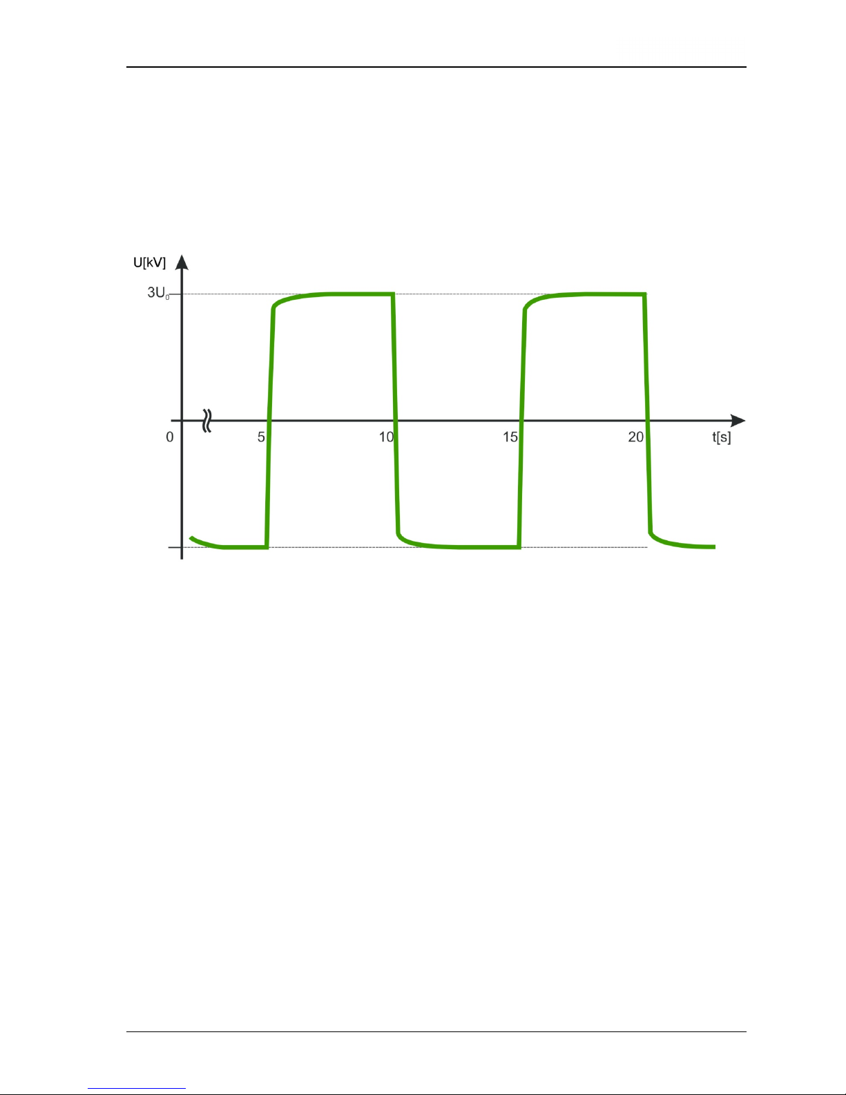
A system that meets these requirements has to supply a 0.1 Hz oscillation, with the quick
polarity reversal taking place within a frequency close to the power frequency.
Fig. 1: Time frame of polarity reversal (type Plus)
Load-dependend frequency during polarity inversion:
TDS40Basis
40 ≤ f < 410 Hz
TDS40Plus
30 ≤ f < 410 Hz
TDS60Basis
55 ≤ f < 475 Hz
TDS60Plus
40 ≤ f < 475 Hz
VLF CR 0.1 Hz
polarity reversal
Oscillation with
30 … 475 Hz
(see below)
Page 17
2-17
Another vital characteristic to be considered when designing this system was to ensure
simple on-site testing by
- small dimensions,
- light weight and
- low power consumption.
Every cycle starts with a charging phase in which the test object as well as the back-up
capacitor switched in parallel are charged from a DC source until the desired test voltage
is reached.
Fig. 2: Shape of 0.1 Hz cosine-rectangular VLF voltage (type Plus)
After a period of 5 seconds, the voltage source will be disconnected from the system
resp. discharged via a resistance.
Subsequently, the polarity reversal is initiated. The test voltage changes its polarity from
minus to plus.
Depending on the size of capacitance of the connected test object, time of the polarity
reversal is between 1 and 17 ms.
Due to the losses which occur during the polarity inversion, the positive voltage is always
decreased by these losses.
After a 5 seconds dwelling period at positive polarity (device option Basis) or equalisation
of the polarity reversal losses due to recharging by the positive DC voltage source
(device option Plus), the return to negative polarity takes place.
The negative voltage source is reconnected to the test object.
Page 18

2-18
The loss of voltage caused by twice changing the polarity (device option Basis) will now
be compensated for by recharging with the negative DC source. In contrast to this at the
device option Plus the losses of a polarity reversal are immediately compensated.
The back-up capacitor has the following tasks:
- It slows the ring-around event down to the ms range even for short cables,
- It compensates a part of the losses during the polarity reversal.
Page 19
2-19
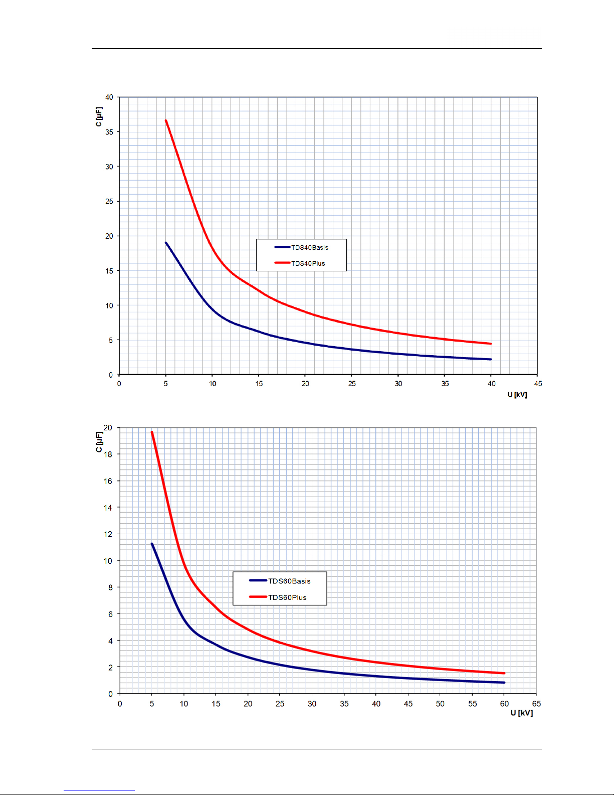
2.6 Testable Cable Capacitance in VLF Mode
Page 20

2-20
2.7 Cable Capacitance that Can be Diagnosed in DAC Mode
TDS40
TDS60
Page 21
2-21
2.8 Description of Components
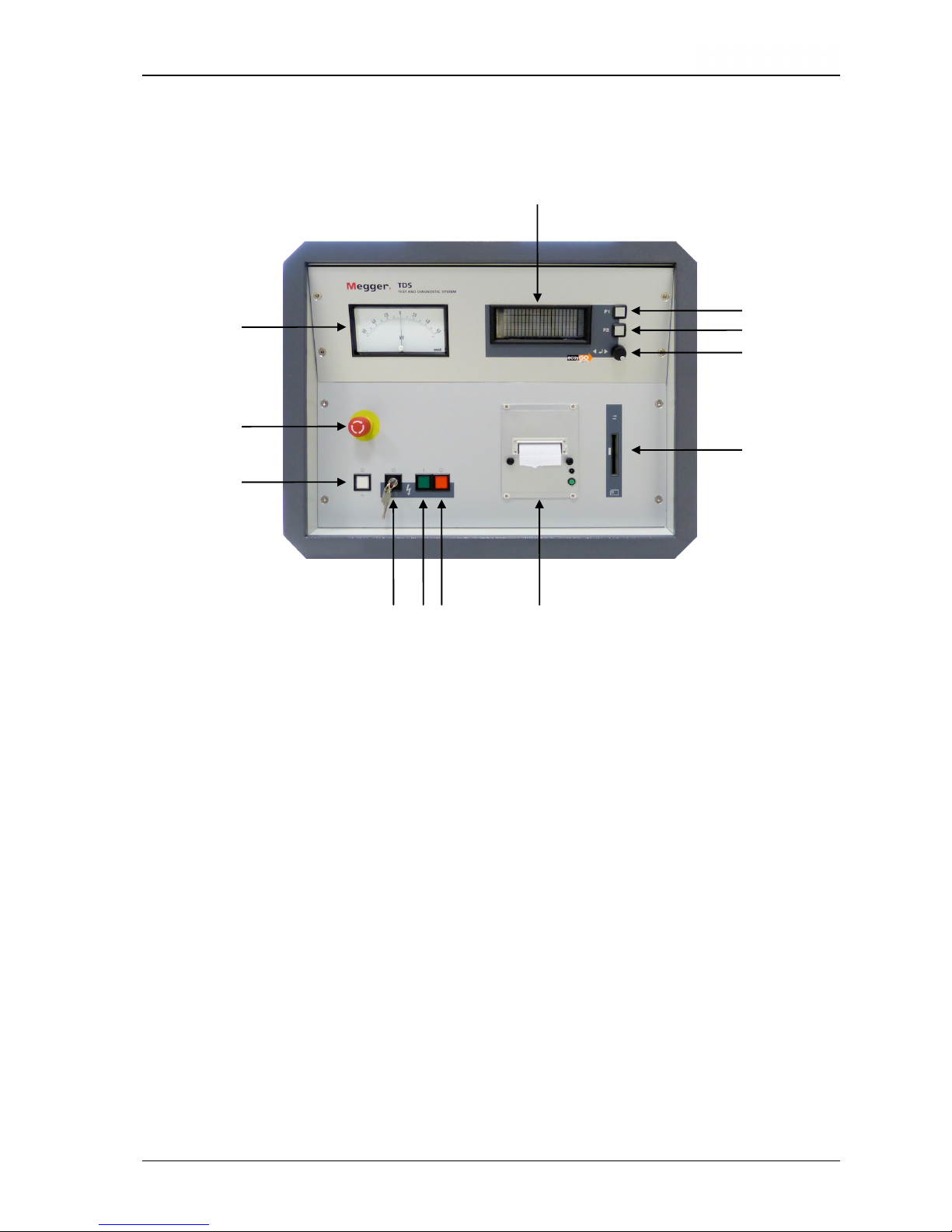
2.8.1 Operating Module
Fig. 3 Operating module - Front View
1 Key "Emergency Off"
2 Analogue indication instrument test voltage (kV)
3 Display
4 Menu key F1
5 Menu key F2
6 Knob / push-button
7 Intake slot for the System Card
8 Protocol printer
9 Key "HVOff" (red)
10 Key "HVOn" (green)
11 Key-operated switch "Interlock"
12 Key "Mains On" (white)
3
4
5
6
7
2
1
12
11 10 9 8
Page 22
2-22
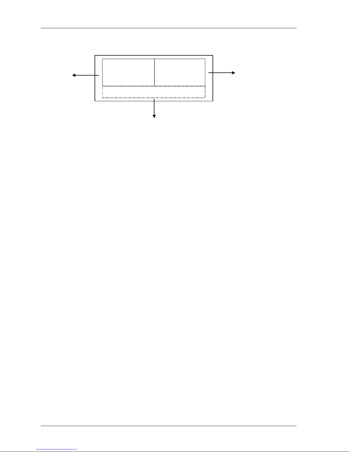
2.8.2 Display of the Operating Module
Fig. 4: Display of the Operating module (View of the standard operating mode)
1 Representation of parameters with value and content resp.
2 Representation of residual time and/or measuring values
3 Representation of operator guidance / status display
Following signals are indicated in the line of operator guidance / status display (Fig. 4,
item 3):
• Operator guidance „Select mode OK?“ e. g.
• Status display „Running. HVOff?“ e. g.
• Switching condition „HV interlock“ e. g.
• Cause for shutdown „Breakdown in cable“ e. g.
• Warning „34: No printer data“ e. g.
• Failure message „19: Coil overload“ e. g.
1
2
3
VLF mode
10kV
5min
0.
0kV
0.00mA
Prepared . HVOn?
Page 23

2-23
2.8.3 Connections
Fig. 5: Connections (in the example of the TDS60)
1 Power supply socket with F1, F2
2 Terminal clip for earth connection of the Operating module
3 Terminal clip for earth connection HV module
4 RJ45 network socket for the connection with the notebook
(required for remote control)
5 Connector socket for connection line to PDS 60
6 Test voltage output
7 Terminal clip for signal ground
4
2
3
5
1
7
6
Page 24

2-24
2.8.4 Protection Covers of the Module
VLF
Test System
Fig. 6: Protection cover of the Operating module
!
Fig. 7: Shorting device / Protection cover of the HV module
Page 25

2-25
2.8.5 Transportation Protection Bottom from the Operating Module
Fig. 8: Transportation protection bottom from the Operating module
Pull out in order to remove
the transportation protection
bottom
Pull out in order to remove
the transportation protection
bottom
Push in in order to fix
the transportation
protection bottom
Push in in order to fix
the transportation
protection bottom
Page 26

Page 27

3-27
3. SETTING UP OPERATION
3.1 Safety Precautions
Before starting any operation, always observe the 5 rules of safety:
• Disconnect the test object
• Protect it against reclosure
• Check for absence of voltage
• Connect it to earth and short-circuit it
• Cover all neighbouring parts carrying voltage or seal them off by a barrier
In order to prevent any damage to persons and/or installations that might directly be
caused by the operation of the test and diagnosis system alone or in combination with
other systems or instruments, always observe the following safety precautions:
Make sure there are no unprotected systems or system components carrying voltage in
the immediate vicinity of the test and diagnosis system with which you or your system
may unintentionally get into contact. This applies in particular to all components under
high voltage or components the voltage of which is not known.
Protect these components by putting up insulating covers. If, for technical reasons, this
cannot be done, disconnect these components or have them disconnected for the
duration of your test at this site after having consulted the relevant supervisor and asked
for his/her permission. Make sure this measure is carried out properly.
Take a test measurement using an appropriate voltage meter. Beforehand, check the
proper operation of this meter, e.g. by taking a test measurement of a known voltage.
Position your system in a place suitable with regard to its dimensions and its weight.
Check whether the system stands in a stable position.
Make sure that the site where the HV module is situated is vented properly to avoid the
accumulation of ozone during lengthy periods of operation.
Make sure that no other system/system component is restricted in its operation by the
presence of your test and diagnosis system. If due to the installation and operation of
the test and diagnosis system some changes have to be made on another
system/system component, always make sure that the former condition is restored after
all operations have been concluded. Observe the special requirements of these
systems/system components without fail, and start any operation on them only after
having consulted the supervisor in charge and asked for his/her permission.
Page 28

3-28
This applies in particular to all changes made on an existing safety device.
The test and diagnosis system TDS40 generates during the test process a dangerous
test voltage up to 40 kV or the test and diagnosis system TDS60 a test voltage up to 60
kV resp. The test voltage is fed via the HV connecting cable in the test object.
Protect the test object against unintentional contact of persons to active parts by means
of protective devices (handrails, chains, bars, etc.) which guarantee that no one can get
into the zone of danger.
Disconnect the test object to ensure that no dangerous voltage can get to unprotected
places or unprotected technical equipment.
Whenever the test and diagnosis system is operated, a second person must be present
within viewing and hearing distance who can recognise possible hazards and press the
Emergency Off key.
Never leave the test and diagnosis system unattended while operating.
In order to avoid dangerous charging, connect all metal parts in the vicinity of the test
and diagnosis system to earth.
As a matter of principle, all unused cables not needed for the test have to be shorted
and connected to earth.
Attention! The test object has to be connected to earth and shorted after terminating
of the test.
You are not excused from this duty even if the complete discharge by the
internal discharging unit and the zero positioning of the residual voltage
(Fig. 3, item 2) have been performed.
In the case of an incomplete discharge of the test object the complete
discharging must be carried out with a suitable discharge rod.
Page 29

3-29
Attention! The HV module of the test and diagnosis system contains electrical
energy storage devices also. These devices are discharged in the same
way like the test object by the internal discharging unit of the test device.
To avoid the re-charging by space charges the HV module has to be
immediately equipped by means of the provided shorting device (Fig. 7)
after disconnection of the both components HV module and Operating
module. The shorting device has to be remained at the HV module even in
the case of transportation and storage and may not be removed until the
Operating module had been put on.
Attention! Before each use it has to be checked whether the following components of
the system are intact, dry and clean:
* HV-connector (device side) and end termination (test object side) of
the movable high-voltage connecting
* HV- output socket of the HV module
* HV connector between HV module and operating module
3.2 Electrical Connection for Stand-alone Test Operation
3.2.1 General Rules for Making Connections
Always keep in mind that you are required to comply with all relevant safety precautions
for high voltage and power systems when you bring the system into service!
In particular, make sure that the test object is connected to earth and shorted and the
cable testing apparatus is switched off when it is connected to the test object or
disconnected from it.
It is only for the duration of intrinsic testing that this short-circuit and earth connection
may be removed.
Please regard the discharge switch contained in the device only as a facility for
discharging the capacitors without risk. Do not use it for earthing and shorting according
to VDE 0104!
Page 30

3-30
3.2.2 Procedure
The descriptions in this section solely apply to the stand-alone operation. The
features regarding the electrical connection in order to diagnose partial
discharge are described in the manual of the discharge
measurement system
PDS 60.
Fig. 9: Connection scheme
The earth cable has be connected to the protective earth system of the
station at an appropriate point and then to be attached to the Terminal clips
of the operating module (see Fig. 5, item 2) and of the HV-module (see Fig.
5, item 3).
The HV connection cable with its HV connector has to be plugged into the
HV module (see Fig. 5, item 6) and to be fixed by turning the latch. The
terminal clip for signal ground has to be plugged into the appropriate
connection (see Fig. 5, item 7).
Afterwards the test cable is connected to the earthed test object.
Plug the mains cable supplied with the system into the power supply socket
(see Fig 5, item 1) and connect it to a mains outlet.
Page 31

3-31
3.2.3 Connection of the External Safety Device (Optional)
The optional external safety device can be connected in between the power outlet and
the power inlet in order to ensure norm-compliant signalling and Emergency Stop
according to DIN EN 50191 / VDE 0104.
Fig. 10: Connection of the external safety device
As soon as the system has been connected to a mains outlet, the red signal light lights
up and signals that high voltage could be generated.
By using the Emergency Stop button or key-operated switch, the power supply can be
interrupted abruptly or be locked. A system that is currently operating is completed
turned off and the discharge switch closed. High voltage cannot be generated, which is
indicated by the green lamp.
Page 32

Page 33

4-33
4. Operating in Stand-alone Test Mode
This manual solely describes the operating of the test and diagnosis system
TDS40/60 in the stand-alone mode.
For information on operating the system by
remote control
in order to diagnose partial discharge please read the manual of
the operating system TDS NT.
4.1 VLF- / DC-Test
For high voltage tests by using the test and diagnosis system to be carried out, all
electrical connections must have been established as described in sections before.
Now the test system can be put into operation. After activation of the "Mains On"
pushbutton (Fig. 3, item 12) the system can be operated using the knob / push-button (Fig.
3, item 6) and the display (Fig. 3, item 3).
The following start menu is represented on the display (Fig. 3, item 3) after start-up:
Fig. 11: Start menu
A singular pressure on the knob / push-button (Fig. 3, item 6) will enable the operation
mode to be selected:
Fig. 12: Selection of the operation mode
Now the user is able to choose the operation mode out of VLF, DC– and DC+ (only
available on systems with two voltage sources) by turning the knob / push-button (Fig. 3,
item 6). The selection has to be confirmed by a singular pressure on the knob / pushbutton (Fig. 3, item 6). Now it is possible to select the test voltage level:
*VLF mode
20kV
15min
Select Mode ? OK?
VLF mode
20kV
15min
F1:Print
F2:Setup
Ready . OK:Start
Page 34

4-34
Fig. 13: Selection of the test voltage
The test voltage level can be adjusted in steps of 1 kV up to the maximum test voltage of
the system by turning the knob / push-button (Fig. 3, item 6). The adjusted test voltage
level has to be confirmed by pressure on the knob / push-button (Fig. 3, item 6). Now it is
possible to adjust the test time:
Fig. 14: Selection of the test time
The test time can be adjusted in steps of 1 min from 5 min up to 45 min and in steps of 5
min from 45 min up to 90 min test duration at maximum by turning the knob / push-button
(Fig. 3, item 6). The adjusted test time has to be confirmed by pressure on the knob /
push-button (Fig. 3, item 6).
Use the information given in DIN VDE 0276 - 620 and 0276 - 621 as a guideline to start
from. These standards recommend a test level of 3 x Uo and a test duration of 30 or 60
minutes, respectively.
When you follow these guidelines, the test level is near the peak voltage of a 50 Hz test (2 x
U0 rms).
For sheath tests with DC voltage, the test voltage should not exceed 3 kV for PVC cables or
5 kV for PE cables respectively.
VLF mode
20kV
*15min
Set test time ? OK?
VLF mode
*2
0kV
15min
Set Voltage ? OK?
Page 35

4-35
4.2 Sheath Fault Location
Following a failed sheath test with DC voltage fault location based on the step voltage
method can be immediately performed at the cable under test with the test and diagnosis
system serving as voltage source.
The test current coming from the pulsed DC source is flowing into the ground at the point
of fault and results in a maximum step voltage at the fault. This peak is located with an
earth fault locator (e.g. ESG).
By turning the knob / push-button (Fig. 3, item 6) the SFL operation mode has to be
selected. Afterwards, the voltage level (max. 10 kV) and the pulse rate can be selected as
described in the section before.
By changing the pulse rate you can vary the cycle period too (between 4 or 6 seconds).
E.g. the setting 4s 1:3 enables 4 seconds cycles where 1 second of high voltage is
followed by a 3 seconds dropout.
Fig. 15: Selection of the pulse rate
SFL mode
10kV
*4s 1:3
Set pulsing . OK?
Page 36

4-36
4.3 Starting the Test / Location
After the system has carried out all necessary settings which takes a short period of time,
the high voltage can be enabled.
Fig. 16: Switching on high voltage
It depends on the following conditions whether or not HV can be switched on using the
respective pushbutton (Fig. 3, item 10):
- the key "Emergency Off" (Fig. 3; item 1) is not activated,
- the key-operated switch "Interlock" (Fig. 3; item 11) is activated,
- both the Operating and the HV module are assembled in proper form.
If these conditions have been fulfilled, the "HVOn" key (green) (Fig. 3, item 10) lights up for
about 10 s and can be activated during this time. Afterwards, the "HVOff" key (red) (Fig. 3,
item 9) lights up. Under maintaining of the predetermined charging parameters the test
voltage will be regulated to the adjusted test voltage level.
At the analogue indication instrument (Fig. 3, item 2) and on the display (Fig. 3, item 3) the
level and the polarity of the test voltage are represented. In addition, the leakage current of
the test object is indicated on the display (Fig. 3, item 3).
By default, the measurement values for the voltage and the leakage current are updated
every 5 seconds at a defined moment (in the VLF mode directly before the start of the
polarity reversal. These logged measured values are displayed in square brackets (e.g.
[10.1 kV]) and remain in the display until the next moment of the next measurement.
Fig. 17: Display of the logged measurement values
VLF mode
20kV
15min
11:42
[20.1kV]
[0.13mA]
Running . HVOff?
VLF mode
20kV
15min
0.0kV
0.00mA
Prepared . HVOn?
Page 37

4-37
By using the menu button F2 (Fig. 3, item 5) the user can switch at any time to the display
with the instantaneous data. The instantaneous data are displayed without square
brackets and updated every 100 ms.
Fig. 18: Display of instantaneous data
If the button F2 is pushed again, the display changes back to the logged measured values.
Beyond this, by clicking the menu button F1, the user can switch between the display of
the remaining time and the set voltage value (e.g. !10.0 kV!).
Fig. 19: Display of the set voltage value
VLF mode
20kV
15min
!20.0kV!
[20.1kV]
[0.13mA]
Running . HVOff?
VLF mode
20kV
15min
11:32
3.6kV
0.02mA
Running . HVOff?
Page 38

4-38
During normal operation, the voltage source is / can be switched off
- by pressing the "HVOff" key (red) (Fig. 3, item 9)
- automatically after the lapse of the test time
- automatically after a voltage breakdown in the cable under test or a short
circuit has been detected
In these cases the predefined discharging of the voltage source, back-up capacitor and
test object follows.
Fig. 20: Start menu after the test has been finished
In addition, the voltage source is / can be switched off
- by activating the “Emergency Off” switch (Fig. 3; item 1),
- by turning the HV interlock key switch (Fig. 3; item 11)
- after drop out of the operating voltage
- by removing a system card which has been inserted prior to the test (see
section 6.4)
- after detection of an internal failure (see section 7.5)
In these cases the predefined discharging of the voltage source, back-up capacitor and
test object follows too.
Attention ! The test object has to be connected to earth and shorted after termination of
the test.
You are not excused from this duty even if the complete discharge by the
internal discharging unit and the zero positioning of the residual voltage
(Fig. 3, item 2) have been performed.
In the case of an incomplete discharge of the test object the complete
discharging must be carried out by a suitable discharge rod.
After the test session has been finished, the test system has to be switched off.
Afterwards, it must be disconnected from the cable under test which has been grounded
and shorted before. Finally, the earth cable has to be disconnected.
VLF mode
20kV
15min
F1:Print
F2:Setup
Test time over
Page 39

5-39
5. Additional Functions
5.1 Adjustment of Language
By pressing the F2 key (Fig. 3, item 5) and turning the knob / push-button (Fig. 3, item 6)
the "User setup" menu can be accessed. Here the language on the display and in the
protocol printing of the test and diagnosis system can be adjusted. Any new setting will be
saved after pressing of the knob / push-button (Fig. 3, item 6).
Fig. 21: User Setup: Language
5.2 Viewing the System Information
By pressing the F2 key (Fig. 3, item 5) and turning the knob / push-button (Fig. 3, item 6)
the "System info" menu can be accessed. When accessing this menu, the software
versions of several system components and the system ID, you should have on-hand
when calling a service centre, are shown on the display. In some cases the system ID is
also required for the subsequent activation of optional system features. A short instruction
how to enable optional system features is handed out with the certificate you get when
buying one or more options.
Fig. 22: Setup: System information
*System info
ID:12345678
1.21-1 1.21-1 1.21
USER PROT CTRL
User-Setup
*Language: English
Level : Standard
Select user language?
Page 40

5-40
5.3 Viewing / Setting the System Parameters
Certain test parameters in the test and diagnosis system are permanently stored as
system parameters and secured against unauthorized changes. As a standard user you
can only view these parameters. In order to adjust these parameters you have to gain
administrator rights by entering the administrator password first (see section 5.4).
By pressing the F2 key (Fig. 3, item 5) and turning the knob / push-button (Fig. 3, item 6)
the "Parameters" menu can be accessed. Provided you own administrator rights (see
section 5.4), the following parameters can be adjusted:
Fig. 23: Setup: Parameters
• Adjustment of the maximum test voltage in kV: By this adjustment the maximum
output voltage of the system can be permanently restricted in the space of its standard
data. Any re-setting can be only carried out by the administrator. The standard
maximum voltage of the test system represents the default setting.
• Adjustment of the rate of the test voltage increase v in kV/s: By this means the rate
of increase of the test voltage during the charging phase can be adjusted. Any resetting can be only carried out by the administrator. The default setting is 1 kV/s.
• Adjustment Step in kV: By this means the increment at stepwise increasing of the test
voltage during the charging phase can be adjusted. Any re-setting can be only carried
out by the administrator. The default setting is 5 kV.
• Adjustment Pause (rest period) in s: Here the duration of the rest period at stepwise
increasing of the test voltage during the charging phase can be adjusted. Any re-setting
can be only carried out by the administrator. The default setting is 0 s.
Parameters <A>
*max.60kV
step 5kV
v= 1kV/s pause 0s
Set HV parameters ?
Page 41

5-41
5.4 Entering / Changing the Administrator Password
By pressing the F2 key “setup” (Fig. 3, item 5) and turning the knob / push-button (Fig. 3,
item 6) the "Password" menu can be accessed. When entering this menu, you have to
enter the administrator password in order to gain the administrator rights enabling you to
adjust the test parameters accessible via the “Parameters” menu (see section 5.3). The
factory-provided default password for any VLF test system is 2345.
The first two digits of the password (23) have to be entered under 1. and the last two digits
(45) have to be entered under 2. Any entered number sequence has to be confirmed by
pressing the knob / push-button (Fig. 3, item 6).
Fig. 24: Setup: Enter password
The access will be gained, if the correct password has been entered. The respective
system message has to be confirmed by pressing the knob / push-button (Fig. 3, item 6).
You are now authorised as an administrator which is indicated by the characteristic <A> in
the top right of the display.
Fig. 25: Setup: Entered password ok
*Password <A>
43:Access released
Password
*1.: 00
2.: 00
Enter password
Page 42

5-42
After the password has been entered and accepted, it can be changed.
In order to change the password, you have to access the “Passw. Set” menu right after
you gained administrator rights. The new password has to be entered the same way as the
current password has been entered (see previous page).
Fig. 26: Setup: Enter new password
Fig. 27: Setup: New password stored
5.5 Returning to the Start Menu
In order to return to the start menu you have to access either the “Return” or the “Escape"
menu item.
If you leave the setup via “Return” (fully to the left), you lose the administrator rights.
If you leave the setup via “Escape” (fully to the right), you keep the administrator rights.
Fig. 28: Setup: Return to start menu
*Return <A>
Your selection ?
*Passw. Set <A>
55:Password stored
Passw. set <A>
*1.: 00
2.: 00
Change password ?
Page 43

6-43
6. Optional Features
6.1 Detection of Breakdown and Short Circuit
Systems with the optional breakdown and short circuit detection offers the following
additional functions:
The test voltage will be immediately switched off in any case of a breakdown in the cable
under test. The status message "Cable break down" is indicated on the display.
The level of the break down voltage is indicated on the display. That value is represented
as storage voltage (i.e. in parentheses).
In case of a short circuit (test voltage < 5% of rated voltage), the test voltage will be
switched off. The status message "Cable cannot be charged" is indicated on the display.
Fig. 29: Breakdown detection
6.2 Measurement of Leakage Current
If a system is equipped with the optional Leakage Current measurement, the leakage
currents of the test object are indicated on the display during the test.
During charging period, the instantaneous measurement values are indicated on the
display. Afterwards, the VLF final values are indicated on the display. The final values (test
voltage and leakage current) are represented in brackets. Change-over to the
representation of the instantaneous measurement values (values without parentheses or
brackets) and back can be carried out by activating the F2 key.
If the test and diagnosis system has been additionally equipped with the logging option or
protocol printout option, these measurement values can be additionally filed and printed
out respectively.
VLF mode
20kV
15min
6:32
(20.1kV
)
(0.19mA)
Breakdown in cable
Page 44

6-44
6.3 Internal Protocol Printout
Systems, that are equipped with a protocol printer (Fig. 3, item 8), offer the opportunity to
print those data that have been logged during the cable test.
By pressing the F2 key (Fig. 3, item 5) and turning the knob / push-button (Fig. 3, item 6)
the "Protocol" menu can be accessed. Here you can change the settings of the printer by
adjusting the “Print” parameter. The value of the parameter can be changed by rotating the
knob / push-button (Fig. 3, item 6) and can be accepted / saved by pressing it.
Fig. 30: Setup: Protocol printout off
Fig. 31: Setup: Protocol Printout Standard
After a cable test has been finished, the protocol printout can be triggered from the start
menu (Fig. 9) by pressing the F1 key once or repeatedly.
Depending on the print settings (see above), the following information are included in the
printout:
• Printout "Standard":
- Header (extended by the header from the SystemCard (if specified))
- System type and version
- Mode of operation, test voltage, test time
- Date / Time of test start
- Result of the test
- Measured data (time, test voltage in kV, leakage current in mA) of the test
(affected by the “print time points” set on the SystemCard (if specified))
- Footer (extended by the footer from the SystemCard (if specified))
- Date / Time of the printout
Protocol
Prot.: Extended
*Print: Standard
Set print mode ?
Protocol
Prot.: Extended
*Print: Off
Set print mode ?
Page 45

6-45
• Printout „Extended“:
- All information listed under “Standard”
- Maximum test voltage, test voltage increase, step increment, rest period
of the ramp (ramp pause)
- Settings for logging and printing
- User profile, service / administrator mode (if applicable)
- Measured data (time, test voltage, current) of the charging period
• Printout „Detailed“:
- All information listed under “Extended”
- A bunch of measuring data logged right before the end of the test
For systems equipped with the logging option (see section 6.4), up to 4 header lines and 4
footer lines (e.g. the company name or a field for the signature of the operator) can be
specified.
These so called individual “print templates” can be imported into the system using a
SystemCard (see section 6.4.2). It depends on the settings of the SystemCard whether
these print templates are permanently stored in the test system configuration or are only
valid for the period of the cable test under way.
In order to test the layout of the individual header lines and footer lines you can initiate a
test printout even if no cable test has been performed before. For this purpose, you have
to change the print settings to “Text” or “System” first. Afterwards, you can initiate the test
printout from the start menu by pressing F1.
Depending on the print settings, the following information are included in the printout:
• Printout „Text“:
- Header (extended by the header from the SystemCard (if specified))
- System type and version
- Footer (extended by the footer from the SystemCard (if specified))
- Date / Time of the printout
• Printout „System“:
- All information listed under “Text”
- All information about the system configuration (options, software
versions)
- If necessary, all calibration data from the system
Page 46

6-46
Attention: When initiating a test printout ("Text" or “System”), any set of measuring data
that may have been logged during a previous cable test will be deleted.
Attention: Immediately change the print settings back to your normal protocol printout
mode after you performed a test printout.
Note: a SystemCard is used with the system (see section 6.4), make sure that when
parametrizing the SystemCard under “WinkisVFL”, the "Settings: Protocol printout"
parameter has been set to [set on device]. Otherwise, the print settings are automatically
adopted from the SystemCard and cannot be changed manually.
Page 47

6-47
6.4 Cable Tests using a SystemCard
6.4.1 SystemCard and „WinkisVLF“
If the test and diagnosis system has been equipped with the logging option, the measured
data can be saved to a so-called SystemCard which has the dimensions of a conventional
credit card.
The SystemCard can be used to store and transfer logged data (see section 6.4.3) and to
hand over predefined test parameters to the system (see section 6.4.2).
In order to format and, if required, parametrize a SystemCard and to analyze / archive the
logged measuring data, the software WinkisVLF has to be used. For detailed information
about the WinkisVLF software, please refer to its online help.
In general, a SystemCard can be used for the following purposes:
• A SystemCard can be prepared for storing measured data only (Protocol card). No
test parameters are handed over to the system. The card may also contain header
lines and footer lines for printouts (see section 6.3) which, however, are only valid for
the cable test under way.
• A SystemCard can be prepared for parametrizing the system (Parameter card). In
this case, the SystemCard changes the settings of the system as specified under
WinkisVLF before. The card may also contain header lines and footer lines for printouts
(see section 6.3). Both, the parameters handed over by the SystemCard are and the
print templates are not permanently stored on the system and only valid for the cable
test under way.
• A SystemCard can be prepared for both parametrizing the system and storing the
measured data. The parameters handed over by such a SystemCard are not
permanently stored on the system and only valid for the cable test under way. The card
may also contain header lines and footer lines for printouts as well as “print time points”
(see section 6.3).
• A SystemCard can be prepared for parametrizing the system in a way that the
parameters handed over by the SystemCard change the device settings
permanently. The card may also contain header lines and footer lines for printouts
(see section 6.3) which are also permanently stored on the system.
Attention: This type of card cannot be used for storing measured data.
Page 48

6-48
6.4.2 Parametrising the SystemCard
Using a SystemCard appropriately parametrized under WinkisVLF will enable you to make
volatile (only for the cable test under way) or permanent changes to your device settings.
Depending on how the card has been parametrized, either all or only certain test
parameters are affected.
That way, cable tests can be planned and prepared in the office using WinkisVLF. Later,
on site, you only have to plug the SystemCard into the system in order to change the
system settings the way it has been planned.
Furthermore, this will allow you to prepare volatile print templates (individual header lines
and footer lines for the ongoing cable test) or non-volatile print templates (as default
protocol template for permanent use) (see section 6.3).
By defining “print time points” using WinkisVLF you can also schedule the logging timeline.
These “print time points” are only valid for the cable test under way and cannot be stored
permanently.
For detailed information about the WinkisVLF software, please refer to its online help.
The parameters stored on a SystemCard are automatically adopted by the test and
diagnosis system right after the card has been plugged into the respective slot on the
control unit (see section 6.4.4).
Page 49

6-49
6.4.3 Logging to SystemCard
By activating the logging function, measuring data logged during a cable test can be
written to a SystemCard. These data may consist of system information, system / test
settings, information about the course of the cable test, the measured data (test voltage,
leakage current) and the test result.
Back in the office, the logged data can be transmitted from the card to a PC where it can
be analyzed and archived using the WinkisVLF software.
For detailed information about the WinkisVLF software, please refer to its online help
By pressing the F2 key (Fig. 3, item 5) and turning the knob / push-button (Fig. 3, item 6)
the menu "Protocol" can be accessed. Here the logging mode (“Prot.”) of the test and
diagnosis system can be adjusted by rotating the knob / push-button and saved by
pressing it.
Fig. 32: Setup: Protocol off
Fig. 33: Setup: Protocol extended
Protocol
*Prot.: Extended
Print: Standard
Set protocol mode ?
Protocol
*Prot.: Off
Print: Standard
Set protocol mode?
Page 50

6-50
Depending on the logging mode, the following data are saved to the SystemCard:
• Protocol „Off“:
If the protocol mode is set to “Off”, no measured data is written to the
SystemCard.
• Protocol „Standard“:
- System type and version
- Test settings relevant for analysis
- Date / time of test start
- Result of the test and remaining test time
- Measured data (time, test voltage in kV, leakage current in mA) of the test
• Protocol „Extended“:
- All information listed under “Standard”
- Measured data (time, test voltage, current) of the charging period
Hint: Setting the protocol mode to "Standard" or "Extended" requires a
SystemCard to be plugged in.
Hint: After a test run has been finished, the system card has to remain in the slot
until the system is completely discharged (status message appears).
Otherwise, data may be lost.
6.4.4 Operating the Test and Diagnosis System with a SystemCard
In order to use a SystemCard for parametrizing the test and diagnosis system or storing
the logged data, the card has to be plugged into the respective slot (Fig. 3; item 7) of the
control unit prior to the start of the cable test (while the start menu is visible).
If it is a valid card, the parameters and other relevant information are read out from the
card. The operator has to identify the card as “Proper Card ?“ while the test parameters
obtained from the card are shown on the display.
After the card has been acknowledged by pressing the knob / push-button, the system
performs some more checks of the system card (e.g. available logging memory on the
SystemCard) whereupon the start menu should look as follows (Fig. 34):
Fig. 34: Start menu with system card inserted
VLF mode
20kV
15min
F1:Print
F2:Setup
By card OK:Start
Page 51

6-51
From now on, only the test parameters which have been specified as [set on device] under
WinkisVLF can be manually changed. This does also apply for the parameters accessible
via the setup menu (F2 key).
If the card is removed from the slot, the settings are undone and the standard start menu
appears on the display.
A cable test can be started as described in section 4.1.
Attention! If the SystemCard is removed during an ongoing cable test, the test is
interrupted!
For the special case of a SystemCard intended to change the settings of the test system
permanently (see section 6.4.1), the settings (test parameter, print templates etc.) are
handed over and stored in the system right after the card has been identified as a “Proper
Card ?”. Afterwards, the start menu looks as follows and the card has to be removed from
the slot.
Fig. 35: Start menu after new system settings have been stored
VLF mode
25kV
30min
F1:Print
F2:Setup
Card data stored.
Page 52

6-52
6.5 Function User Setup / User Level
By pressing the F2 key (Fig. 3, item 5) and turning the knob / push-button (Fig. 3, item 6)
the menu "User Setup" can be accessed.
After administrator rights have been gained as described in section 5.4, the “User Setup”
menu can be used to change the user level. That function is of importance when logging to
SystemCard (see section 6.4.3) or parametrizing the system using a SystemCard (see
section 6.4.2).
Fig. 36: Setup: User profile
By setting the user level to “Single”, the system can only be operated with a parametrized
SystemCard. That way, the users operating the system on-site are not allowed to change
test parameters not specified as [set on device].
By setting the user level to “Standard”, the system can be operated with or without
SystemCard.
Attention! Only the user level “Standard" allows the system to be operated without
SystemCard.
User-Setup <A>
Lang.: English
*Level: Standard
User level ?
Page 53

6-53
6.6 Re-Setting the System Settings / Deleting the Print Templates
The user interface of the test and diagnosis system allows you to reset the non-volatile
system settings back to the default factory settings and to delete permanently stored print
templates.
After administrator rights have been gained as described in section 5.4, the “Memory”
menu can be accessed via the “Setup” menu. The functions of this menu can be activated
by pressing the F1 key or F2 key respectively. By pressing the knob / push-button the
menu can be left without triggering a function.
Fig. 37: Setup: Memory
„F1: Reload setup” resets all parameters and system settings to the default factory
settings. The administrator password is not affected (see section 5.4).
“F2: Delete Texts” resets all print templates (individual header lines and footer lines)
stored on the system (see section 6.3).
Hint: These functions are not accessible, if a System Card inserted.
Memory <A>
F1: Reload setup
F2: Delete texts
F1/F2? else OK
Page 54

6-54
6.7 Adjustment of the System Time
If the test and diagnosis system is equipped with at least one of the system options
“Logging” or “Protocol printout”, the system contains a battery-operated and crystalcontrolled clock (see section 7.3).
After activating of the Menu key F2 (Fig. 3, item 5) and by turning the knob / push-button
(Fig. 3, item 6) the menu "Date / Time" can be accessed. Here the date and the clock time
of the system timer (test and diagnosis system) can be adjusted. By turning the knob /
push-button, the value of the selected segment is changed. You can toggle through the
segments by pressing the knob / push-button.
After all segments have been set, the date and time can be stored by pressing the F1 key.
By pressing the knob / push-button again, the changes are discarded.
Fig. 38: Setup: Date / Time
Fig. 39: Setup Date / Time: Adjusting the day of the week
Fig. 40: Setup Date / Time: Adjusting the minutes
Fig. 41: Setup Date / Time: Saving by F1
Date/Time
Mo 19.06.08 10:27:13
*
F1= Set! else OK
Date/Time
Mo 19.06.08 10:27:13
*
Set date & time
Date/Time
Mo 19.06.08 10:27:13
*
Set date & time
Date/Time
Mo 19.06.08 10:27:13
F1= Set! else OK
Page 55

7-55
7. Repair and Fault Diagnostics
Repair and maintenance work has to be carried out by Megger or authorised service
partners using original spare parts only. Megger recommends having the system tested
and maintained at a Megger service centre once a year.
This test allows, amongst others, checking the gas pressure of the discharge switch and
the state of the HV switch.
Megger also offers its customers on-site service. Please contact your service centre as
needed.
7.1 Replacing Fuses
If the device cannot be switched on, even though it is connected to the mains power
supply, both fuses below the power supply socket must be checked. The fuse holder must
be pulled out to do so.
If the fuses are defective, they must be replaced with suitable microfuses (5 x 20 mm) of
the type T2.5A. Disconnet from the mains before changing a fuse.
If the fuses continue to trip, please get in touch with the Megger service department in
order to have the problem resolved.
Page 56

7-56
7.2 Exchanging the Paper Roll or Ink Ribbon of the Printer
The optional built-in printer is housed in a robust metal case with removable front cover.
To exchange the paper roll or the ink-ribbon cartridge, first remove the front cover from the
printer.
a ) Removing the front cover
Turn both knurled screws anti-clockwise (Fig. 42) until the front cover comes off the printer
(Fig. 43).
Fig. 42: Unscrewing the printer front cover
Fig. 43: Removing the front cover
b ) Exchanging the ribbon
In order to exchange the ribbon, press down the left edge of the ink ribbon cartridge
marked "Push" and "Eject" (Fig. 44). The cartridge will come off on the right-hand side and
can now be removed. Tighten the ribbon of the new cartridge by turning the small wheel
on the right-hand side, following the direction of the arrow. After that, guide the ribbon
cartridge over the paper. See to it that the paper is between the textile ribbon and the
plastic bridge (Fig. 45). Let the ink cartridge engage distinctly. If you encounter blurred or
unbalanced printing, improper engagement of the ink cartridge is very likely to be the
cause.
Fig. 44: Removing the ribbon cartridge Fig. 45: Inserting the ribbon cartridge
Page 57

7-57
c ) Exchanging the paper roll
The container can hold paper rolls with up to 50 mm diameter.
First follow step b and remove the ribbon cartridge. Remove the spindle from the core of
the empty roll and insert it into the core of the new paper roll.
If necessary, cut the front edge of the paper strip in a straight line. Hold the paper roll in
your hand and thread the front end of the paper from below into the slot of the printer unit
intended to this purpose (see Fig. 46) until you sense some resistance. To lead the paper
past the print head, press the paper feed button (Fig. 47) until approx 5 cm (2 inches) of
paper stand out of the printer unit.
Insert the new paper roll with the spindle into the paper container und tension the paper.
After that, again insert the ribbon cartridge into the printer unit, as described in step b.
Fig. 46: Inserting the paper roll into the printer Fig. 47: Paper feed button
d ) Attaching the front cover
Lead the paper from the rear through the front cover and again screw the front cover onto
the printer.
7.3 Replacing the Battery of the System Clock
If the test and diagnosis system is equipped with at least one of the system options
“Logging” or “Protocol printout”, the system contains a crystal-controlled clock. The built in
lithium cell is capable of powering the clock for several years.
If this battery needs to be changed, please contact the next service centre.
Page 58

7-58
7.4 Connecting Cables, HV Couplings
Maintenance and troubleshooting include regularly checking the connecting cables such
as earth cables, mains cables and test cables for being in good repair. In addition to that
we recommend that the HV couplings at the Operating module and HV module should be
checked with regard to mechanical integrity and cleanness.
Make absolutely sure that after use the HV plug of the test voltage cable is again covered
with the included protective sleeve.
7.5 Operational and Error Messages
7.5.1 Classification of Messages
Operational and error messages occurring during the operation of the test and diagnosis
system are classified as follows:
Symbol
Class
Response
What to do
U
Operational message
about state of system
refer to instruction
manual
C
Operational message
about switching
condition
confirm - continue
operation
F
Error of type "fatal"
HVOff
confirm - restart system
T
Error of type "trans"
HVOff
confirm - repetition
possible
N
Error of type "normal"
HVOff
confirm - repetition
possible
W
Warning
none
confirm - continue
operation
R
Messages in remote
control mode
different
No operational action
possible at the system
itself
For detailed information about the messages, please refer to the following paragraphs.
Page 59

7-59
7.5.2 Operational Messages about State of System
The following operational messages inform the operator about the current state of the
system.
You don´t need to confirm any of them. The system, however, expects the operator to
make one of the entries listed in the table.
Code
Cl. Operational message Description Input
- - [ Start-up screen]
System is starting up.
none
- U Connecting...
System is connecting
Master and Slave
processors.
none
- U Initiating system
System is initializing
parameters etc.
none
- U Remove any card !
No card must be plug-
ged in during start-up.
none pull out
card !
- U Ready. OK:Start
System is ready for
starting a test.
OK (or to
Setup)
- U By card. OK:Start
System is ready for
starting a test.
OK (or to
Setup
- U Stopped. OK:Start
System is ready for
starting a test.
OK (or to
Setup)
- U Select mode OK?
System is waiting for
input of mode.
rotary knob + OK
- U Set voltage OK?
System is waiting for
input of test voltage.
rotary knob + OK
- U Set test time OK?
System is waiting for
input of test time.
rotary knob + OK
- U Set pulsing OK?
System is waiting for
input of pulsing rate.
rotary knob + OK
- U Insert SystemCard
System is waiting for a
system card to be
inserted.
none insert
card !
- U Without card only
Operation mode can
only be performed
without system card
none pull out
card !
- U Card is invalid !
System card not
readable or invalid.
none pull out
card !
- U Card is full !
System card is full.
none pull out
card !
Page 60

7-60
Code
Cl. Operational message Description Input
- U Card is faulty !
Content of system card
is faulty.
none pull out
card !
- U Really this card ?
System is waiting for
confirmation of card.
OK - U
Reading card...
System is reading data
from the system card.
none
- Checking...
System is checking the
read data
none
- U Card data stored
Non-volatile storage of
data
none pull out
card !
- U Preparing...
System is setting up
parameters.
none
- U Prepared. HVOn?
System is waiting for
"HVOn".
HVOn or OK
(abortion)
- U Turning on...
System is starting up
after "HVOn".
none
- U Running. HVOff?
System is preparing
high voltage.
HVOff or OK
- U Holding. HVOff?
System is preparing
high voltage.
HVOff or OK
- U Discharging...
System is discharging
and earthing after
"HVOff".
none
- U F1=retry F2=reboot
System is waiting for a
decision after error.
F1 or F2
- U Press F2 to reboot
System is waiting for
reboot after fatal error.
F2 - U
Rebooting...
System is going to
reboot .
none
- U Printing...
Device-internal protocol
printing under way.
none
- U Your selection ?
In Setup: Prompting to
select from menu.
rotary knob + OK
- U Set HV-parameters
In Setup: Prompting to
make entry
rotary knob + OK
- U Set protocol mode
In Setup: Prompting to
make entry
rotary knob + OK
- U Set print mode
In Setup: Prompting to
make entry
rotary knob + OK
- U Set user language
In Setup: Prompting to
make entry
rotary knob + OK
Page 61

7-61
Code
Cl. Operational message Description Input
- U Set user level
In Setup: Prompting to
make entry
rotary knob + OK
- U F1= set! else OK
In Setup: query for
setting the clock
F1: set or OK
(abortion)
- U Set date & time
In Setup: Prompting to
make entry
rotary knob + OK
- U Enter code number
In Setup: Prompting to
make entry
rotary knob + OK
- U Enter password
In Setup: Prompting to
make entry
rotary knob + OK
- U Change password
In Setup: Prompting to
make entry
rotary knob + OK
- U F1/F2 ? else OK
In Setup: query of
"Memory"
F1 or F2 or OK
(abortion)
- U F1/F2 ? else OK
In Setup: query of
"Calibration"
F1 or F2 or OK
(abortion)
- U Set service mode
In Setup: Prompting to
make entry
rotary knob + OK
- U Set configuration
In Setup: Prompting to
make entry
rotary knob + OK
- U System is locked.
In Setup: no access
authorization
Config. code needed
to obtain access.
- U Values are fixed.
In Setup: no access
authorization.
Password needed to
obtain access.
- U Unknown message
A user message has
been called that is
unknown to the system.
Software trouble -
must not occur during
operation
Page 62

7-62
7.5.3 Operational Messages about Switching Conditions
The following operational messages inform the user about the switching conditions prior to
"HVOn" and about the cause of shut-down after "HVOff". These messages need to be
confirmed by the operator with "OK" unless they disappear on their own accord after
having set a switching condition.
Code
Cl. Operational
message
Description Input
- C Checking...
After the parameters have
been set, the switching
conditions are being
queried.
No action required,
only information
- C HV interlock
Detachable key switch is
switched off.
Switch detachable key
switch on
- C Emergency switch
Internal emergency switch
has tripped.
Switch emergency
switch on
- C Ext. safety loop
External safety loop is
open.
Close emergency loop
- C Door contact(s)
At least one door contact
is open.
Close doors of vehicle
- C Module coupling
Connection between
modules is interrupted..
Connect modules
- C SF6 pressure
SF6 gas pressure in HV
switching system is below
rated value.
Gas pressure monitor
at present not functional, check signal on
module
- C Humidity sensor
Degree of dew condens-
ation on system is above
permissible limit.
Dew monitor at present
not functional, check
signal on module, if
need be
- C HV connector
The HV cable is not
properly connected at the
HV connector
Connect the HV cable
- C Ground monitor
Earth monitoring is
reporting inadequate
protective earth
connection.
Check the electrical
connections /
grounding conditions
- C Cable shield
Earth monitoring is
reporting inadequate
operational earth
connection.
Check the electrical
connections /
grounding conditions
Page 63

7-63
Code
Cl. Operational
message
Description Input
- C Breakdown in cable
High voltage has been
switched off by system
after breakdown in cable.
Possible result of a
cable test
- C Cannot be charged
High voltage has been
switched off by system
due to breakdown of
voltage.
Possible result of a
cable test
- C Test time over
High voltage has been
switched off by system
after test time has
elapsed.
No action required
- C HVOff by OWTS-M
HV is switched off via the
connected OWTS system
No action required
- C HVOff by system
High voltage has been
switched off by system
after a fault has occurred.
No action required,
refer to error list
- C Unknown message
A condition message has
been called up that is
unknown to the system.
Software trouble -
must not occur during
operation
Page 64

7-64
7.5.4 Error Messages and Warnings
With the exception of operating errors, every error, once it has occurred, is reported by
way of a two-digit error code. Each of these messages needs to be confirmed by the
operator with "OK", further procedures are determined by the system.
Code
Cl. Operational
message
Description Input
00 F Unknown error
An error message has
been called that is
unknown to the system.
Software trouble -
must not occur during
operation
01 F Event overflow
The software buffer of
events in the master has
overflown.
Software trouble - may
occur during operation
only if there is an unusual
accumulation of errors
02 F Slave not found
The master has not
received any acknowledgement of receipt from
the slave via LON.
LON Bus / wiring / power
supply
03 F Slave not ready
The master has not
received any confirmation
from the slave on its
request.
LON Bus / wiring / power
supply
04 F Unknown slave
The software version of
the slave is not compatible with the software
version of the master.
Insert Slave PROM with
suitable software version
05 F Master timeout
Communication between
master and slave is interrupted (slave does not
respond).
LON Bus / wiring / power
supply
06 F P-node missing
A protocol node
registered in Setup does
not answer to the
network.
Check protocol node and
its linkage as well as
power supply
07 F Config. restart
The system needs to be
rebooted after the device
configuration has been
changed.
Initiate restart by
confirmation of error
message
08 F State mismatch
The slave is unable to
carry out the requested
transition of condition.
Software trouble - must
not occur during
operation
Page 65

7-65
Code
Cl. Operational
message
Description Input
09 F Unknown
master
The software version of
the master is not
compatible with the
software version of the
slave.
Insert Master Flash with
appropriate software
version
10 F Slave timeout
Communication between
master and slave is
interrupted (master does
not respond any more).
LON Bus / wiring / power
supply
11 F Slave is locked
The slave does not per-
form a task requested by
the master owing to
preceding errors.
Software trouble - must
not occur during
operation
12 F VOK
malfunction
The so-called operation
stand-by of module
"Control node VLF…"
has broken down.
Check hardware signal
VOK on module, check
cable between LON and
module
13 F SPI data error
In the slave the exchange
of data between LON
node and module
"Control" is interrupted.
Hardware damage / EMC
trouble in module, check
cable between LON and
module
14 T Parameter error
The slave does not per-
form any parameter
setting because the set of
parameters is faulty.
Software trouble - must
not occur during
operation
15 T Turn on failed
Error when opening the
discharge unit and/or
when switching the HV
source(s) on.
Check return and control
lines to discharge unit
and HV sources
16 T NOT
DISCHARGED
Danger ! The system
cannot ensure proper discharging after "HVOff".
Manually discharge by
external means, check
return and control lines to
discharge switches
17 T Turn off failed
Error when closing the
earthing switch and/or
when switching the HV
source(s) off.
Check return message
and control lines to
discharge switches and
HV sources
18 N HVOn line error
In the slave the so-called
HV contactor (module:
K2) is reported switched
on in spite of being
locked
Check control line of
relay K2 as well as
hardware signal KISON
on module
Page 66

7-66
Code
Cl. Operational
message
Description Input
19 N Jumper
changed
Jumper coding of module
"Control node VLF…"
has been changed during
operation.
Undo changes or make
changes only when
system is switched off
20 N Module coupling
The connection between
the modules of the system has been interrupted.
Restore connection,
check hardware signal
COUPL on module
21 N SF6 pressure
The SF6 gas pressure in
the HV switching system
is below limit.
Gas pressure monitor at
present not functional,
check hardware signal
PRESS on module
22 N GND SWITCH
OPEN
Danger! The system
cannot ensure proper
earth protection.
(only 80 kV systems)
Manually discharge by
external means, check
return and control lines to
discharge switches
23 N Feed switch on
At least one of either
charge switches has not
opened.
Check control of either
charge switches and
hardware signal XXXn on
module
24 N Dischg. switch
The discharge switch has
not opened.
Check control of
discharge switch and
hardware signal XXXn on
module
25 N HV source on
Return message from a
switched-off HV source
reports source switched
on.
Check HV sources, their
mains lines as well as
hardware signals
N/PISON on module
26 N HV source(s) !
The return messages
expected from either HV
sources have broken
down or are wrong.
Check HV sources, their
mains fuses and
hardware signals
N/PISON on module
27 N Coil overload
Current monitor in slave
reports overcurrent
through the VLF ringaround coil.
Reduce load at HV output
of system or magnitude
of high voltage
28 N HV polarity +
Polarity monitor in slave
reports wrong (positive)
polarity at HV measuring
divider.
Check operation of HV
thyristors (ring-around
may have not taken
place)
29 N HV polarity -
Polarity monitor in slave
reports wrong (negative)
polarity at HV measuring
divider.
Check operation of HV
thyristors (ring-around
may have not taken
place)
Page 67

7-67
Code
Cl. Operational
message
Description Input
30 N VOLTAGE
FOUND
Danger! Voltage monitor
in reports residual voltage
at HV measuring divider.
Eliminate possible
residual voltage
manually. Check
discharge switches and
voltage monitoring.
31 N Overvoltage
Voltage monitor in slave
reports overvoltage at HV
measuring divider.
Check voltage control of
HV sources, check
measuring divider
32 N Meas. Overflow
Voltage monitor in slave
reports overflow of
voltage divider.
Hardware damage / EMC
trouble on module, check
HV measuring divider
33 N Card removed
The system card has
been removed during a
cable test.
Remove the system card
only after the cable test
has been finished!
34 N Card is full
The system card is full
prior to or during the
cable test.
The required memory
space on the card can
only be guessed before
testing.
35 N Bad card format
There is a formatting
error on the system card.
Card/Device/Command
Header erroneous,
print text line too long,
Data Page not empty
36 N No card access
Some error has occurred
when reading from or
writing on system card.
Access to card is via
I²C-Bus in protocol node.
Contacts of card clean ?
37 N Protocol error
There has been an error
in the timing of measuring
data and their recording
in the protocol.
The protocol node checks
the measuring data
received from contro
node with time stamp.
38 W Config. changed
The jumper encoding of
module "Control node
VLF…" is found changed
during start-up.
Any change to the
encoding is reserved to
the Customer Service
and manufacturer!
39 W Memory written
Non-volatile device
settings have been reset
to their default values at
the time of delivery.
This is a receipt message
after "Reload setup" or
"Delete texts".
40 W Bad card param.
Erroneous parameters
found on the system card
have been reset to
default values.
Call parameters up to
display (also in Setup)
and check their usability.
Page 68

7-68
Code
Cl. Operational
message
Description Input
41 W Setup is faulty
System of conditions on
master inhibits start of HV
operation if user level is
inappropriate.
Software trouble - must
not occur during operation
42 W Access denied
Entered password is
wrong and will be
rejected.
To administrator,
customer service und
manufacturer: Enter
correct password!
43 W Access released
Entered password is right
and will be accepted.
To administrator,
customer service und
manufacturer: Access to
extended Setup is
granted.
44 W Not accepted
Entered password is
illegal and will be
rejected.
To administrator,
customer service und
manufacturer: Enter
approved password!
45 W Relaxed mode
on
The slave is operating in
Relaxed mode after the
respective adjustment
has been made in Setup.
Must not occur during
operation - Relaxed
mode is reserved for
customer service!
46 W DEMO MODE ON
The system has been set
to demo mode via the
setup menu.
Should not appear during
regular operation. Demo
mode is only for service
purposes.
47 W C-values stored
Calibration data have
been changed by entry
and stored on slave in
non-volatile mode.
Any change of calibration
data is reserved for
customer service and
manufacturer !
48 W Not calibrated
System has not been
calibrated / calibration
data in slave have been
lost (possibly only in
parts).
Perform initial calibration
/ Call customer service,
as initial calibration is
reserved for customer
service!
49 W No print data
No data are availabe for
built-in protocol printing.
Record protocol, data will
be available till next
"HVOn".
50 W Printer error
The built-in protocol
printer is not ready for
operation.
Check protocol printer
and its linkage as well as
power supply
51 W IIC-Bus error
Some error has occurred
when reading from or
writing on the real-time
clock.
Access to the real-time
clock is via I²C Bus in
protocol node. System
card involved?
Page 69

7-69
Code
Cl. Operational
message
Description Input
52 N Check sum error
Some check-sum error
has occurred when
reading from the system
card.
Data are stored on card
in an EEPROM. Life time
expired?
53 W Unlocked
system
Only in test lab:
Automatic configuration
interlock is blocked.
Only in test lab:
Enable configuration
interlock manually!
54 W Code accepted
Entered configuration
code has been accepted
by the respective device.
Configuration authority
has been granted, access
to configuration setup is
open.
55 W Password
stored
Entered administrator
password has been
stored and is accepted.
Help can be given quickly
should you have
forgotten your password
(specify Device-ID).
56 N Incompat. card
The system card contains
a wrong Device-ID or
Command-ID.
Check your version of
“WinkisVLF” and perform
an update if necessary.
57 F Illegal config.
Configuration data of
master and slave differ.
Software problem. Must
not appear during regular
operation.
58 N NOT
GROUNDED
Danger! The system
cannot ensure proper discharging after "HVOff".
(only 80 kV systems)
Manually discharge by
external means, check
return and control lines to
discharge switches.
59 N Cal. by DC only
The system cannot be
calibrated in the active
operation mode.
Only for service:
Choose DC mode.
60 W St-data stored
Statistic data have been
reset.
Pure confirmation
message.
61 W Mainten.
Required
Maintenance is required
due to the high amount of
operating hours.
Please make an
appointment with your
nearest SebaKMT serice
station.
62 R Ignition error
After the cable has been
charged the Thyristor
switch wasn´t operated.
Indicates a hardware
fault.
The cable is presumably
still charged -> Press
“HVOff”, discharge
manually (!) and earth.
63 R DAC overload
The cable couldn´t be
charged within the
set/restricted time frame.
Overload! Load
capacitance presumably
too big.
Page 70

7-70
Code
Cl. Operational
message
Description Input
64 R DAC timeout
Automatic „HVOff“ after
the expiry of a defined
time frame without
commands from the PDmeasurement system
Restart measurement.
68 R Unknown
version
Software version of the
TDS40/60 is not
compatible with the
software version of the
PD measurement system.
Contact service and
enquire about necessary
steps.
69 R Task conflict
Software problem -
must not occur during operating.
70 R Not connected
71 R Watchdog failed
72 R Card inserted
In the remote control
mode a SystemCard has
been inserted.
Remove the SystemCard!
73 R Message lapse
Software problem -
must not occur during operating.
74 R State mismatch
75 R Unknown
request
76 R Parameter error
77 R Lost connection
Communication between
the TDS40/60 and the PD
measurement system has
been interrupted.
Potential interruption of
the cable connection or
crash of the PD software.
Solve the problem and
restart the system.
Page 71

Tento symbol indikuje, že výrobek nesoucí takovéto označení nelze likvidovat společně s běžným domovním odpadem. Jelikož se jedná o produkt obchodovaný mezi
podnikatelskými subjekty (B2B), nelze jej likvidovat ani ve veřejných sběrných dvorech. Pokud se potřebujete tohoto výrobku zbavit, obraťte se na organizaci specializující
se na likvidaci starých elektrických spotřebičů v blízkosti svého působiště.
Dit symbool duidt aan dat het product met dit symbool niet verwijderd mag worden als gewoon huishoudelijk afval. Dit is een product voor industrieel gebruik, wat betekent
dat het ook niet afgeleverd mag worden aan afvalcentra voor huishoudelijk afval. Als u dit product wilt verwijderen, gelieve
dit op de juiste manier te doen en het naar een
nabij gelegen organisatie te brengen gespecialiseerd in de verwijdering van oud elektrisch materiaal.
This symbol indicates that the product which is marked in this way should not be disposed of as normal household waste. As it is a B2B product, it may also not be disposed
of at civic disposal centres. If you wish to dispose of this product, please do so properly by taking it to an organisation specialising in the disposal of old electrical equipment
near you.
Този знак означава, че продуктът, обозначен по този начин, не трябва да се изхвърля като битов отпадък. Тъй като е B2B продукт, не бива да се изхърля и в
градски пунктове за отпадъци. Ако желаете да извърлите продукта, го занесете в пункт, специализиран в изхвърлянето на старо електрическо оборудване.
Dette symbol viser, at det produkt, der er markeret på denne måde, ikke må kasseres som almindeligt husholdningsaffald. Eftersom det er et B2B produkt, må det heller ikke
bortskaffes på offentlige genbrugsstationer. Skal dette produkt kasseres, skal det gøres ordentligt ved at bringe det til en nærliggende organisation, der er specialiseret i at
bortskaffe gammelt el-udstyr.
Sellise sümboliga tähistatud toodet ei tohi käidelda tavalise olmejäätmena. Kuna tegemist on B2B-klassi kuuluva tootega, siis ei tohi seda viia kohalikku jäätmekäitluspunkti.
Kui soovite selle toote ära visata, siis viige see lähimasse vanade elektriseadmete käitlemisele spetsialiseerunud ettevõttesse.
Tällä merkinnällä ilmoitetaan, että kyseisellä merkinnällä varustettua tuotetta ei saa hävittää tavallisen kotitalousjätteen seassa. Koska kyseessä on yritysten välisen kaupan
tuote, sitä ei saa myöskään viedä kuluttajien käyttöön tarkoitettuihin keräyspisteisiin. Jos haluatte hävittä
ä tämän tuotteen, ottakaa yhteys lähimpään vanhojen
sähkölaitteiden hävittämiseen erikoistuneeseen organisaatioon.
Ce symbole indique que le produit sur lequel il figure ne peut pas être éliminé comme un déchet ménager ordinaire. Comme il s’agit d’un produit B2B, il ne peut pas non plus
être déposé dans une déchetterie municipale. Pour éliminer ce produit, amenez-le à l’organisation spécialisée dans l’élimination d’anciens équipements électriques la plus
proche de chez vous.
Cuireann an siombail seo in iúl nár cheart an táirgeadh atá marcáilte sa tslí seo a dhiúscairt sa chóras fuíoll teaghlaigh. Os rud é gur táirgeadh ghnó le gnó (B2B) é, ní féidir
é a dhiúscairt ach oiread in ionaid dhiúscartha phobail. Más mian leat an táirgeadh seo a dhiúscairt, déan é a thógáil ag eagraíocht gar duit a sainfheidhmíonn i ndiúscairt
sean-fhearas leictrigh.
Dieses Symbol zeigt an, dass das damit gekennzeichnete Produkt nicht als normaler Haushaltsabfall entsorgt werden soll. Da es sich um ein B2B-Gerät handelt, darf es
auch nicht bei kommunalen Wertstoffhöfen abgegeben werden. Wenn Sie dieses Gerät entsorgen möchten, bringen Sie es bitte sach
gemäß zu einem Entsorger für
Elektroaltgeräte in Ihrer Nähe.
Αυτό το σύμβολο υποδεικνύει ότι το προϊόν που φέρει τη σήμανση αυτή δεν πρέπει να απορρίπτεται μαζί με τα οικιακά απορρίματα. Καθώς πρόκειτ αι γ ια προ ϊόν B2B, δεν
πρέπει να απορρίπτεται σε δημοτικά σημεία απόρριψης. Εάν θέλετε να απορρίψετε το προϊόν αυτό,
παρακαλούμε όπως να το παραδώσετε σε μία υπηρεσία συλλογής
ηλεκτρικού εξοπλισμού της περιοχής σας.
Ez a jelzés azt jelenti, hogy az ilyen jelzéssel ellátott terméket tilos a háztartási hulladékokkal együtt kidobni. Mivel ez vállalati felhasználású termék, tilos a lakosság
számára fenntartott hulladékgyűjtőkbe dobni.Ha a terméket ki szeretné dobni, akkor vigye azt el a lakóhelyéhez közel működő, elhasznált elektromos berendezések
begyűjtésével foglalkozó hulladékkezelő központhoz.
Questo simbolo indica che il prodotto non deve essere smaltito come un normale rifiuto domestico. In quanto prodotto B2B, può anche non essere smalti to in centri di
smaltimento cittadino. Se si desidera smaltire il prodotto, consegnarlo a un organismo specializzato in smal timento di apparecchiature el ettriche vecchie.
Šī zīme norāda, ka iztrādājumu, uz kura tā atrodas, nedrīkst izmest kopā ar parastiem mājsaimniecības atkritumiem. Tā kā tas ir izstrādājums, ko cits citam pārdod un lieto
tikai uzņēmumi, tad to nedrīkst arī izmest atkritumos tādās izgāztuvēs un atkritumu savāktuvēs, kas paredzētas vietējiem iedzīvotājiem. Ja būs vajadzīgs šo izstrādājumu
izmest atkritumos, tad rīkojieties pēc noteikumiem un nogādājiet to tuvākajā vietā, kur īpaši nodarbojas ar vecu elektrisku ierīču savākšanu.
Šis simbolis rodo, kad juo paženklinto gaminio negalima išmesti kaip paprastų buitinių atliekų. Kadangi tai B2B (verslas verslui) produktas, jo negalima atiduoti ir buitinių
atliekų tvarkymo įmonėms. Jei norite išmesti šį gaminį, atlikite tai tinkamai, atiduodami jį arti jūsų esančiai specializuotai senos elektrinės įrangos utilizavimo organizacijai.
Dan is-simbolu jindika li l-prodott li huwa mmarkat b’dan il-mod m’għandux jintrema bħal skart normali tad-djar. Minħabba li huwa prodott B2B , ma jistax jintrema wkoll
f’ċentri ċiviċi għar-rimi ta’ l-iskart. Jekk tkun tixtieq tarmi dan il-prodott, jekk jogħġbok għamel dan kif suppost billi tieħdu għand organizzazzjoni fil-qrib li tispeċjalizza fir-rimi ta’
tagħmir qadim ta’ l-elettriku.
Dette symbolet indikerer at produktet som er merket på denne måten ikke skal kastes som vanlig husholdningsavfall. Siden dette er et bedriftsprodukt, kan det heller ikke
kastes ved en vanlig miljøstasjon. Hvis du ønsker å kaste dette produktet, er den riktige måten å gi det til en organisasjon i nærheten som spesialiserer seg på kassering av
gammelt elektrisk utstyr.
Ten symbol oznacza, że produktu nim opatrzonego nie należy usuwać z typowymi odpadami z gospodarstwa domowego. Jest to produkt typu B2B, nie należy go więc
przekazywać na komunalne składowiska odpadów. Aby we właściwy sposób usunąć ten produkt, należy przekazać go do najbliższej placówki specjalizującej się w
usuwaniu starych urządzeń elektrycznych.
Este símbolo indica que o produto com esta marcação não deve ser deitado fora juntamente com o lixo doméstico normal. Como se trata de um produto B2B, também não
pode ser deitado fora em centros cívicos de recolha de lixo. Se quiser desfazer-se deste produto, faça-o correctamente entregando-o a uma organização especializada na
eliminação de equipamento eléctrico antigo, próxima de si.
Acest simbol indică faptul că produsul marcat în acest fel nu trebuie aruncat ca şi un gunoi menajer obişnuit. Deoarece acesta este un produs B2B, el nu trebuie aruncat nici
la centrele de colectare urbane. Dacă vreţi să aruncaţi acest produs, vă rugăm s-o faceţi într-un mod adecvat, ducând-
ul la cea mai apropiată firmă specializată în colectarea
echipamentelor electrice uzate.
Tento symbol znamená, že takto označený výrobok sa nesmie likvidovať ako bežný komunálny odpad.Keďže sa jedná o výrobok triedy B2B, nesmie sa likvidovať ani na
mestských skládkach odpadu. Ak chcete tento výrobok likvidovať, odneste ho do najbližšej organizácie, ktorá sa špecializuje na likvidáciu starých elektrických zariadení.
Ta simbol pomeni, da izdelka, ki je z njim označen, ne smete zavreči kot običajne gospodinjske odpadke. Ker je to izdelek, namenjen za druge proizvajalce, ga ni dovoljeno
odlagati v centrih za civilno odlaganje odpadkov. Če želite izdelek zavreči, prosimo, da to storite v skladu s predpisi, tako da ga odpeljete v bližnjo organizacijo, ki je
specializirana za odlaganje stare električne opreme.
Este símbolo indica que el producto así señalizado no debe desecharse como los residuos domésticos normales. Dado que es un producto de consumo profesional,
tampoco debe llevarse a centros de recogida selectiva municipales. Si desea desechar este producto, hágalo debidamente acudiendo a una organización de su zona que
esté especializada en el tratamiento de residuos de aparatos eléctricos usados.
Den här symbolen indikerar att produkten inte får blandas med normalt hushållsavfall då den är förbrukad. Eftersom produkten är en så kallad B2B-produkt är den inte
avsedd för privata konsumenter, den får således inte avfallshanteras på allmänna miljö-
eller återvinningsstationer då den är förbrukad. Om ni vill avfallshantera den här
produkten på rätt sätt, ska ni lämna den till myndighet eller företag, specialiserad på avfallshantering av förbrukad elektrisk utrustning i ert närområde.
 Loading...