

Page 1
WWW.MEGGER.COM
User’s Manual
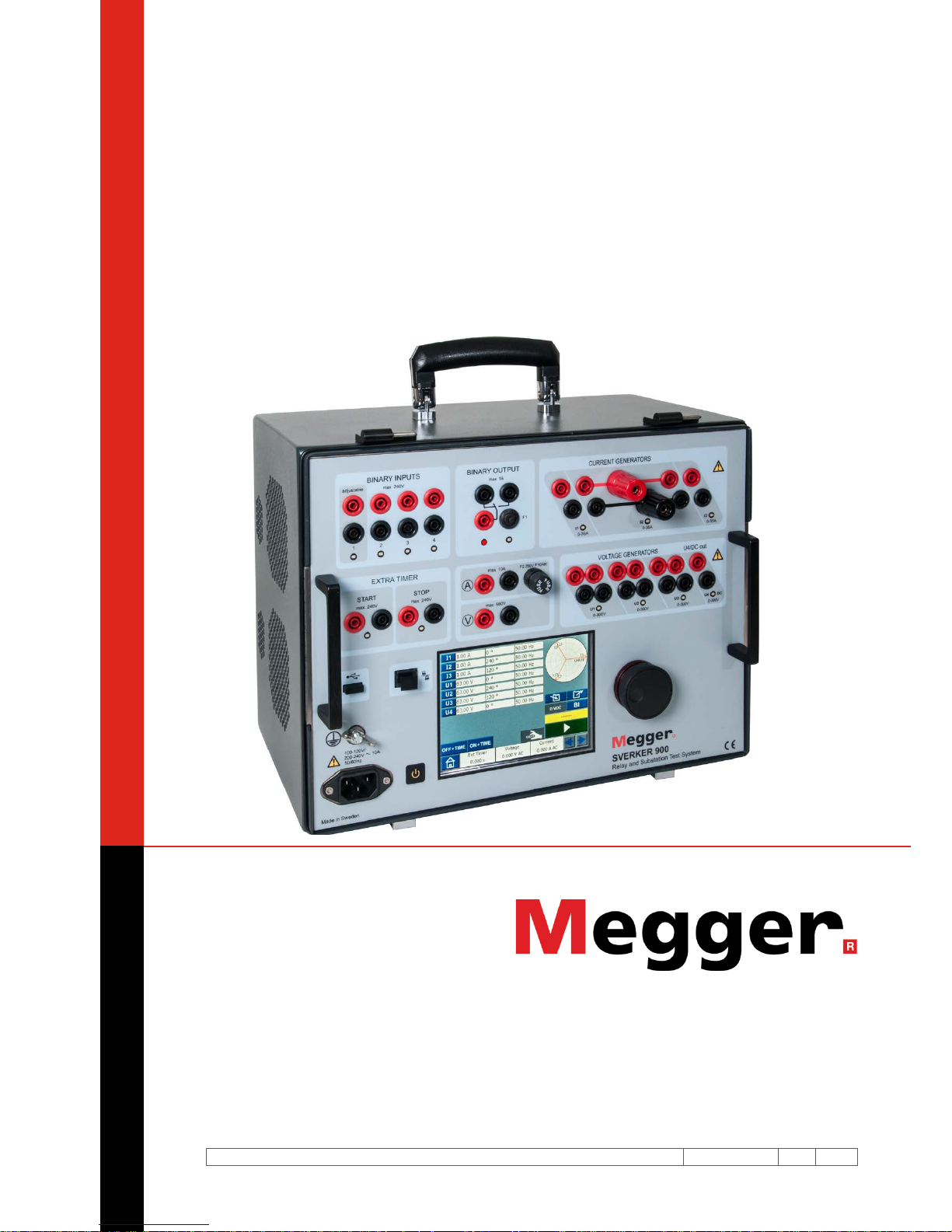
SVERKER900
Relay and Substation Test System
Art No. ZP-CR02E Doc. CR0333LE V12a 2016
Page 2

Page 3

SVERKER900
Relay and Substation Test System
NOTICE OF COPYRIGHT & PROPRIETARY RIGHTS
© 2013-2016, Megger Sweden AB. All rights reserved.
The contents of this manual are the property of Megger Sweden AB. No part of this work may be reproduced or transmitted in any form or
by any means, except as permitted in written license agreement with Megger Sweden AB. Megger Sweden AB has made every reasonable
attempt to ensure the completeness and accuracy of this document. However, the information contained in this manual is subject to change
without notice, and does not represent a commitment on the part of Megger Sweden AB. Any attached hardware schematics and technical
descriptions, or software listings that disclose source code, are for informational purposes only. Reproduction in whole or in part to create
working hardware or software for other than Megger Sweden AB products is strictly prohibited, except as permitted by written license
agreement with Megger Sweden AB.
TRADEMARK NOTICES
Megger® and Programma® are trademarks registered in the U.S. and other countries. All other brand and product names mentioned in this
document are trademarks or registered trademarks of their respective companies.
Megger Sweden AB is certified according to ISO 9001 and 14001.
User’s Manual
Postal address:
Megger Sweden AB
Box 724
SE-182 17 DANDERYD
SWEDEN
T +46 8 510 195 00
F +46 8 510 195 95
seinfo@megger.com
www.megger.com
Visiting address:
Megger Sweden AB
Rinkebyvägen 19
SE-182 36 DANDERYD
SWEDEN
CR0333LE ZP-CR02E SVERKER900
3
Page 4

4 SVERKER900 ZP-CR02E CR0333LE
Contents
1 Safety
............................................................. 6
1.1 General ............................................................... 6
Symbols on the instrument ................................. 6
1.2 Safety instructions ............................................... 6
2 Introduction
............................................................. 8
2.1 General ............................................................... 8
2.1 Unpack system .................................................... 9
2.2 Service and support ............................................ 9
Training ..............................................................9
Contact information ........................................... 9
3 Instrument description
........................................................... 10
3.1 Panel ................................................................ 10
3.2 The lid .............................................................. 10
3.3 Binary Inputs ..................................................... 11
3.4 Binary Output ................................................... 11
3.5 Current generators: I1, I2, I3 ............................. 12
3.6 Voltage generators: U1, U2, U3 and U4 ............ 13
Voltage generator U4 as auxiliary supply ...........13
3.7 Extra timer ........................................................ 14
Start and Stop conditions ................................ 14
3.8 A-meter / V-meter .............................................. 15
Voltage ........................................................... 15
Current ........................................................... 15
Ammeter and Voltmeter windows ..................15
Other entities .................................................... 16
3.9 USB port ........................................................... 16
USB 2.0 Interface ............................................. 16
Firmware upgrade via SVERKER900 USB port ... 16
USB software upgrade .................................... 16
3.10 Ethernet port .................................................. 17
3.11 Low current generation (Optional) .................. 17
4 Operating SVERKER 900
........................................................... 18
4.1 Local interface .................................................. 18
Display buttons ................................................. 18
Momentary buttons ........................................ 18
Switch buttons ............................................... 18
Start SVERKER 900 ........................................... 18
4.2 Home menu ...................................................... 19
Home menu buttons ....................................... 19
System configuration ........................................ 19
Generator configuration ................................... 20
4.3 Main instrument ............................................... 21
Main instrument buttons ................................ 21
Non-generating mode ...................................... 21
Generating mode ........................................... 21
Numerical keypad ............................................. 22
Equals ............................................................. 22
Setting frequency to DC ................................. 22
Balance ........................................................... 22
Finding the pick-up and drop-off value using
the hold function .............................................. 23
Binary Inputs ..................................................... 23
BI window buttons ......................................... 23
Make BI settings ............................................. 24
Trig condition.................................................. 24
Event recording............................................... 24
Debounce filter ............................................... 25
Special settings available for BI1 ...................... 25
4.4 Prefault->Fault instrument ................................ 26
Prefault->Fault view .......................................... 26
Navigation ...................................................... 26
Prefault -> Fault instrument buttons ................. 26
Prefault view ................................................... 27
Fault view ......................................................... 27
Automatic Prefault->Fault button ......................27
The phase angle graph ................................... 27
4.5 Ramping instrument ......................................... 28
Ramping view ................................................... 28
Navigation ...................................................... 28
Ramping instrument buttons .......................... 28
Start a ramp test ............................................... 28
Speed and Stop ramping set views .................. 28
The phase angle graph ................................... 28
4.6 Sequencer instrument ....................................... 29
Navigation ...................................................... 29
Sequencer instrument buttons ........................ 29
Page 5

CR0333LE ZP-CR02E SVERKER900
5
4.7 CT magnetization instrument ............................ 32
CT magnetization instrument buttons ............ 33
Set-up .............................................................. 33
Manual test ...................................................... 33
Manual/auto test .............................................. 34
Auto test .......................................................... 34
Demagnetization .............................................. 35
4.8 Impedance instrument ...................................... 35
Navigation ...................................................... 35
Impedance instrument buttons ....................... 35
Prefault view ..................................................... 36
Fault + Manual pickup search view ...................36
Prefault – Fault view..........................................37
Manual binary search view ................................ 38
The impedance plane graph .............................. 39
4.9 Test file management ........................................ 40
Buttons in Test file management ..................... 40
Save a test ........................................................ 40
Quick save ........................................................ 41
View and reuse test files ...................................41
Storage file ..................................................... 41
Reference file .................................................. 41
Transfer files to PC ............................................ 41
Copy test files from USB stick to SVERKER 900..42
4.10 Calibration ...................................................... 42
Calibration procedure .......................................42
Automatic calibration ..................................... 42
Manual calibration ............................................ 43
Calibration report .............................................43
5 Troubleshooting
........................................................... 44
5.1 Problems ........................................................... 44
Outputs .......................................................... 44
BINARY INPUTS ............................................... 44
Harmonics ...................................................... 44
Voltmeter / Ammeter ...................................... 44
File handling ................................................... 44
EXTRA TIMER .................................................. 44
5.2 Error messages .................................................. 45
5.3 Warning messages ............................................ 45
5.4 Alarms .............................................................. 46
Distortion alarm ................................................ 46
Other generator alarms ..................................... 46
A-meter / V-meter alarm ...................................47
6 Specifications
........................................................... 48
Index ....................................................... 52
Page 6

6 SVERKER900 ZP-CR02E CR0333LE
1 SAFETY
1
Safety
1.1 General
Important
Read and comply with the following instructions.
Always comply with local safety regulations.
Symbols on the instrument
Caution, refer to accompanying documents.
Protective conductor terminal.
WEEE, Waste Electrical and Electronic
Equipment. Please utilize your local
WEEE collection facilities in the disposition of this product and otherwise
observe all applicable requirements.
1.2 Safety instructions
Warning
1]
High voltage/current on output terminals.
2] The instrument is equipped with a power
cord with integral safety ground pin. The
equipment must be connected to a grounded
mains outlet.
The instrument case must also be grounded
by the separate protective ground wire with
connection to the protective earth terminal
on the rear panel. This is to eliminate difference in earth potential between the instrument and the device to be tested. Check the
continuity of the protective ground wire
before each use.
3] Do not attempt to service the instrument
yourself. Opening or removing covers may
expose you to dangerous voltage. If you attempt to service the instrument yourself the
warranty is no longer valid.
4] Do not use any accessories that are not in-
tended for use together with the instrument.
5] Do not use the instrument for any purpose
other than indicated by the manufacturer.
6] If the equipment is used in a manner not
specified by the manufacturer, the protection
provided by the equipment may be impaired.
7] Disconnect the instrument from the mains
before cleaning. Use a damp cloth for cleaning. Do not use liquid cleaners or aerosol
cleaners.
Important
1] Always turn the equipment off before con-
necting.
2] Always use manufacturer approved and sup-
plied cable sets.
3] Always connect protective earth (ground).
4] Slots and openings in the instrument are
provided for ventilation. They ensure reli-
Page 7

CR0333LE ZP-CR02E SVERKER900
7
1 SAFETY
able operations, keeping it from overheating. These openings must not be blocked nor
covered during operation.
5] The instrument may not be positioned so
that the mains switch is blocked.
6] The mains connector may not be used as
disconnecting device.
7] The plug to the mains inlet is to be used as
disconnector.
8] Never leave the instrument unattended while
it is turned on and in the high-current mode.
9] Use only approved mains detachable cable
set with the instrument. Main supply cables
shall be rated for the maximum current for
the equipment and the cable shall meet the
requirements of IEC60799 (Cord sets and interconnection cord sets). Mains supply cables
certified or approved by a recognized testing authority are regarded as meeting this
requirement.
10] Unplug the instrument from the mains sup-
ply when it is left unattended or not in use.
11] Do not expose the instrument to rain or
moisture.
12] Refer all servicing to Megger authorized
personnel.
13] If you need to return the instrument, please
use either the original crate or one of equivalent strength
Page 8

8 SVERKER900 ZP-CR02E CR0333LE
2 INTRODUCTION
2
Introduction
2.1 General
The SVERKER900 is an instrument designed for
testing of electrical equipment e.g. protective relay
systems in substations and industrial plants.
SVERKER 900 comes in three models.
Model Test instruments
Basic Main instrument
Prefault-Fault instrument
Standard Main instrument
Prefault-Fault instrument
Ramping instrument
Sequencer instrument
CT magnetization instrument
Expert Main instrument
Prefault-Fault instrument
Ramping instrument
Sequencer instrument
CT magnetization instrument
Impedance instrument
The rugged hardware design is built for field use over
a wide temperature range.
SVERKER 900 is a three-phase test equipment. It can
generate voltage and current from its four voltage
generators and three current generators respectively,
receive binary inputs and a binary output that is a
make/brake contact.
SVERKER 900 can measure external voltages and currents as well, and properties like level, phase, power
factor and frequency of each. The voltage and current
generator outputs can be activated in many combinations. It also includes an external timer with various
start and stop conditions.
All setting for the instrument are made using the
touch screen. The main instrument includes the
"ON+TIME" and "OFF + TIME" functionality.
Another instrument is the prefault fault sequence with
binary input used for trip signals.
The Ramping instrument is used to ramp voltage, current, angle and frequency. One or several parameters
can be ramped at the same time..
The Sequencer instrument has 16 states that can be
individually configured for parameter value, timing
and BI/BO. Equipment for multi task purpose can be
automatically tested here, e.g. different protections
and parameter limit values.
The CT magnetization instrument is used for manual
or automatic "knee point" control on current transformers.
The Impedance instrument is used for testing in so
called impedance plane, where the conversion from
the impedance into voltage and current is done automatically .
Page 9

CR0333LE ZP-CR02E SVERKER900
9
2 INTRODUCTION
2.1 Unpack system
Unpack the unit and check for evidence of any shipping damage. If there is any visual damage, immediately notify the freight carrier to make a damage
claim, and notify Megger of the damage.
2.2 Service and support
For technical assistance please contact your local
representative or direct your request to Megger in
Sweden.
When sending the instrument, please use either the
original crate or one of equivalent strength.
Add the return authorization number to the address
label of the shipping container for proper identification and quicker handling.
Note Ship the equipment without nonessential
items such as test leads, etc. These items are
not needed by the factory to perform service.
Training
For information about training courses contact your
local distributor or the Megger Sweden office.
Contact information
Internet: www.megger.com
E-mail: support-sweden@megger.com
Tel: +46 8 510 195 00
Fax: +46 8 510 195 95
Page 10
10 SVERKER900 ZP-CR02E CR0333LE
3 INSTRUMENT DESCRIPTION
1
10
8
15
5
2
4
11
14
6
7
9
13
12
3
3
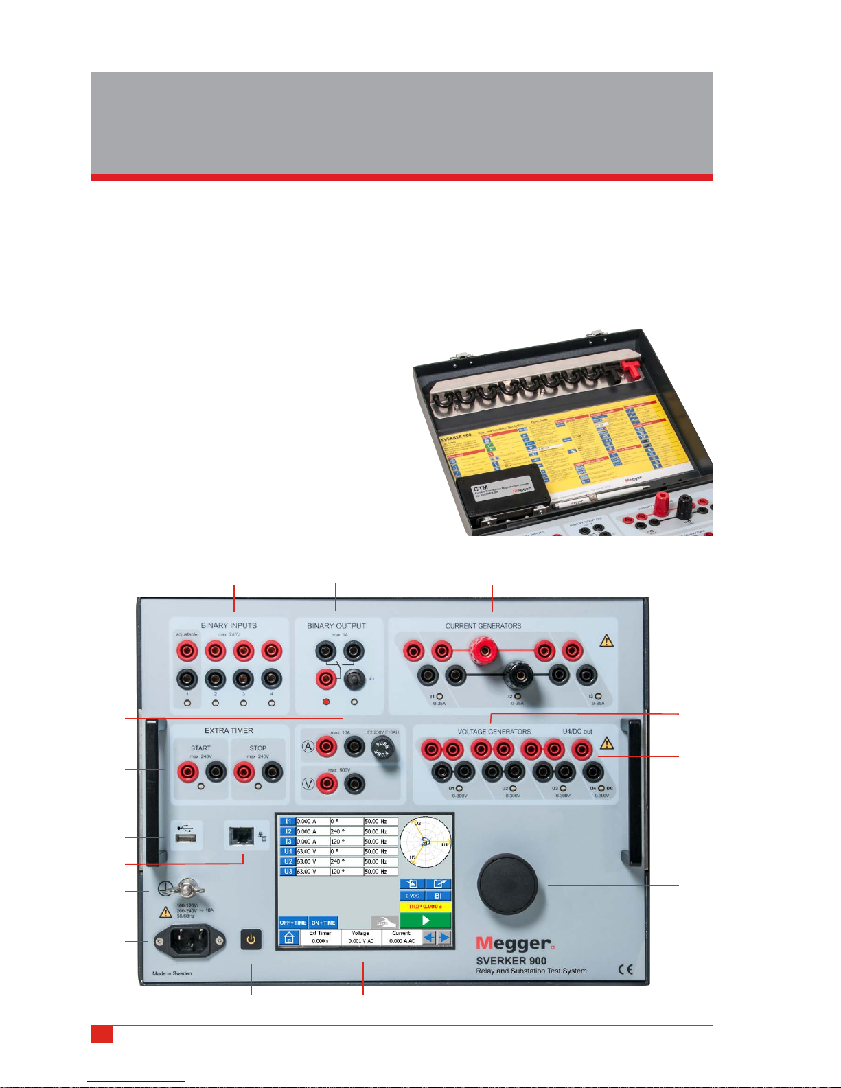
Instrument description
3.1 Panel
1. Binary inputs
2. Binary output
3. F2 fuse
4. Current generators I1, I2, I3
5. Voltage generators U1, U2, U3
6. Voltage generator U4 or AUX supply
7. Control knob
8. Touch screen
9. Power ON/OFF switch
10. Mains inlet socket
11. Protective earth terminal
12. Ethernet port
13. USB port
14. Extra timer
15. Ammeter & voltmeter
3.2 The lid
Inside the lid are:
▪
Jumpers
▪ CTM-box for use with the CT magnetization instrument
▪ Pen to use for the touch screen
Page 11
CR0333LE ZP-CR02E SVERKER900
11
3 INSTRUMENT DESCRIPTION
3.3 Binary Inputs
The SVERKER 900 have 4 binary inputs, independent programmable gate circuits that permit simple
selection of the desired mode for voltage or contact
monitoring operation. Binary input 1 has a selectable
threshold voltage.
The binary inputs are used to monitor relay trip contacts for performing pickup and dropout tests as well
as for performing timing functions.
The binary inputs are specifically designed to measure
high speed operation of electromechanical, solid-state
and microprocessor-based protection relays. All binary
inputs are default set to monitor mode, contact /voltage change of state.
To change a binary input state from contact sensing to
voltage applied / removed, touch the "BI" button.
At each binary input there is an input state indicator
lamp that shows the state of the input. It indicates
either a closed circuit (for contact mode) or the presence of a voltage (for voltage mode). These indicators
permit (for example) to check the circuits involved
before starting a sequence.
Dry contacts
Open
Timer stops and a continuity indicator goes out at the opening of
normally closed contacts.
Dry contacts
Close
Timer stops and a continuity indicator glows at the closing of the
normally open contacts.
Application or
removal of AC
or DC voltage
Timer stops. The continuity indicator will glow (application) or darkens (removal) upon the application
or removal of either an AC or DC
voltage. A higher threshold voltage
helps to eliminate false triggers
due to a noisy source. Lower
thresholds allow starting and stopping of timer from TTL voltage
signals.
Binary input 1 has a settable
threshold value for pickup & dropout and minimum settable threshold voltage is 5 V
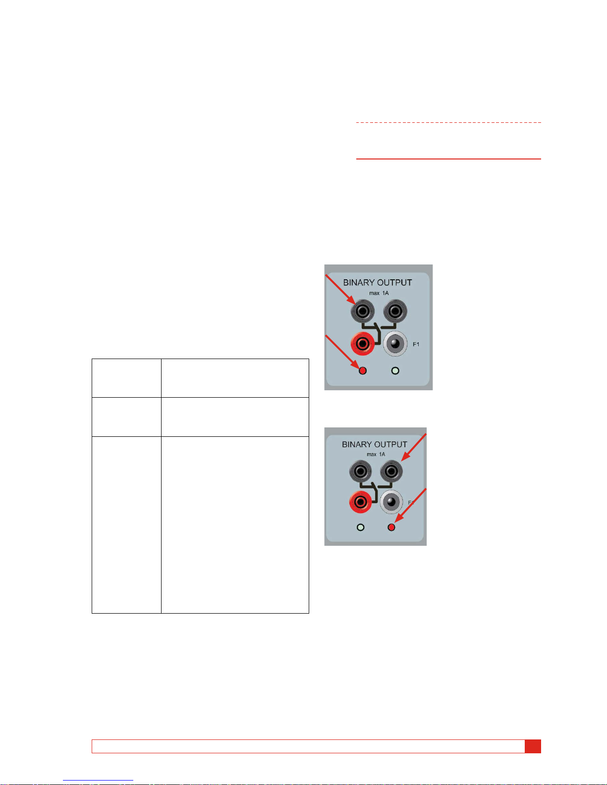
3.4 Binary Output
The binary output is a make/break contact that is
actuated when the SVERKER 900 is set to ON-generating or OFF-generating mode.
Note In the"Sequence instrument" the make/break
contact position can be set for each state
individually.
The binary output is used to simulate normally
open / normally closed contacts for testing breaker
failure schemes, or similar power system operations. In
addition it may also be used to switch AC/DC voltages
and currents.
For maximum switching capacity see the specification
section.
BO position when SVERKER 900 is OFF (not generating).
Left terminal is on.
BO position when SVERKER 900 is ON (generating)
Right terminal is on..
Page 12
12 SVERKER900 ZP-CR02E CR0333LE
3 INSTRUMENT DESCRIPTION
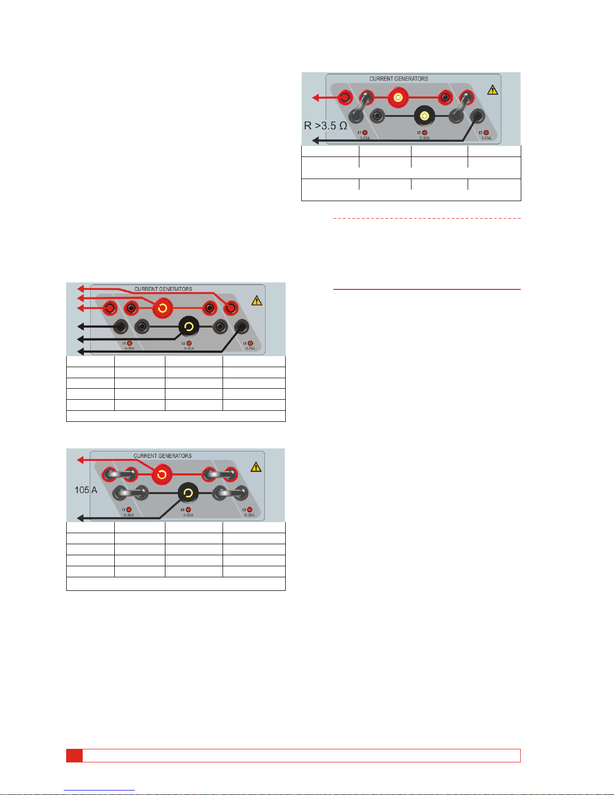
3.5 Current generators: I1,
I2, I3
The current generators can be used separately, in parallel or in series. Constant power output in many cases
eliminates the need to connect the current channels in
parallel or series to test high burden relays.
▪
All outputs are isolated or floating and provide variable
frequency.
▪ The current generators delivers maximum compliance
voltage to the load constantly during the test, and range
changing is done automatically, on-the-fly, under load.
The per channel output current and power ratings are
specified in AC rms values. Specified duty cycles are
based upon ambient temperature of 20°C.
Current generators separately: I1, I2, I3
Current Power (max) Voltage (max) Duty cycle
5 A 250 VA 50 V Continuous
10 A 250 VA 25 V Continuous
20 A 200 VA 10 V Continuous
35 A 100 VA 2.8 V 10 s ON / 20 s OFF*
*Thermo protected
Current generators in parallel: I1 // I2 // I3
Current Power (max) Voltage (max) Duty cycle
15 A 750 VA 50 V Continuous
45 A 750 VA 16.5 V Continuous
60 A 600 VA 10 V Continuous
105 A 300 VA 2.8 V 10 s ON / 20 s OFF*
*Thermo protected
Current gene rators in series: I1 – I2 – I3
Current (max) Power (max) Volta ge (max) Duty cycle
18 A 625 VA 14 0 V Continuous
With external inductive load. Frequency: max 200 Hz
15 A 625 VA 140 V Continuous
With minimum 3.5 Ω external resistive load. Frequency: max 200 Hz.
Note The current amplifiers outputs are protected
from open circuits and thermally protected
against prolonged overloads. In case of an
open circuit or a thermal overload, the amplifier will automatically turn off, and an error
message will be displayed.
Page 13
CR0333LE ZP-CR02E SVERKER900
13
3 INSTRUMENT DESCRIPTION
3.6 Voltage generators: U1,
U2, U3 and U4
The voltage generators can be used separately, in
parallel or in series.
▪
All outputs are independent from sudden changes in
mains voltage and frequency, and are regulated so
changes in load impedance do not affect the output.
▪ All outputs are isolated or floating.
▪ All outputs provide variable frequency.
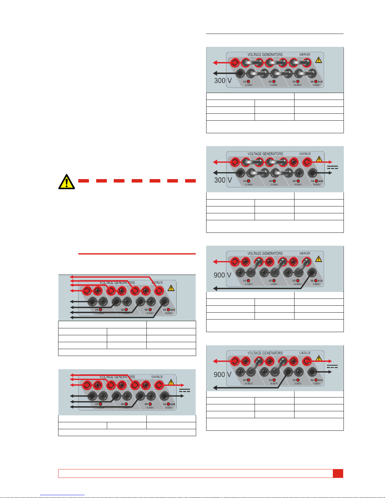
Voltage generator U4 as auxiliary
supply
The primary application for U4 is to provide auxiliary
voltage for protective relays. U4 provides a variable
output from 0 to 300 V AC/DC.
Warning
Do not plug or insert any test lead into
the voltage outputs without first connecting the test leads to the load.
When voltage generators are connected
in series for output over 600 V the special
test leads (brown and purple) must be
used.
Voltage generators separately: U1, U2, U3, U4
Voltage range Power (max) Current (max)
300 V 125 VA 0.42 A
100 V 100 VA 1.0 A
67 V 100 VA 1.5 A
External load: min. 25 Ω
Voltage generators separately: U1, U2, U3 (U4 AUX)
Voltage range Power (max) Current (max)
300 V* 125 VA 0.42 A
* U4 DC
Voltage generators in parallel: U1 // U2 // U3 // U4
Voltage range Power (max) Current (max)
300 V 375 VA 1.2 A
100 V 300 VA 3.0 A
67 V 300 VA 4.5 A
External load: min. 7 Ω
Frequency: max. 200 Hz
Voltage generators in parallel: U1 // U2 // U3 (U4 DC)
Voltage range Power (max) Current (max)
300 V 312 VA 1.0 A
100 V 250 VA 2.5 A
67 V 250 VA 3.7 A
External load: min. 9 Ω
Frequency: max. 200 Hz
Voltage generato rs in series: U1 – U2 – U3 – U4
Voltage range Power (max) Current (max)
900 V 450 VA 0.5 A
400 V 360 VA 0.9 A
268 V 350 VA 1.3 A
External load: min. 100 Ω
Frequency: max. 200 Hz
Voltage generators in series: U1 – U2 – U3 (U4 AUX)
Voltage range Power (max) Current (max)
900 V 350 VA 0.4 A
300 V 280 VA 0.9 A
200 V 275 VA 1.4 A
External load: min. 75 Ω
Frequency: max 200 Hz
Page 14
14 SVERKER900 ZP-CR02E CR0333LE
3 INSTRUMENT DESCRIPTION
3.7 Extra timer
The SVERKER900 has two independent gate inputs
that permit simple selection of the desired mode for
timing operation.
To monitor operation of the contacts in the device
under test, a light is provided for each gate. The gate
circuit is isolated for voltage-sensing and can monitor
solid-state logic signals. Each light will illuminate once
contacts close or voltage is applied to the gate.
1] Press ”Ext Timer” at bottom of display, from
any of the instruments.
A new window opens.
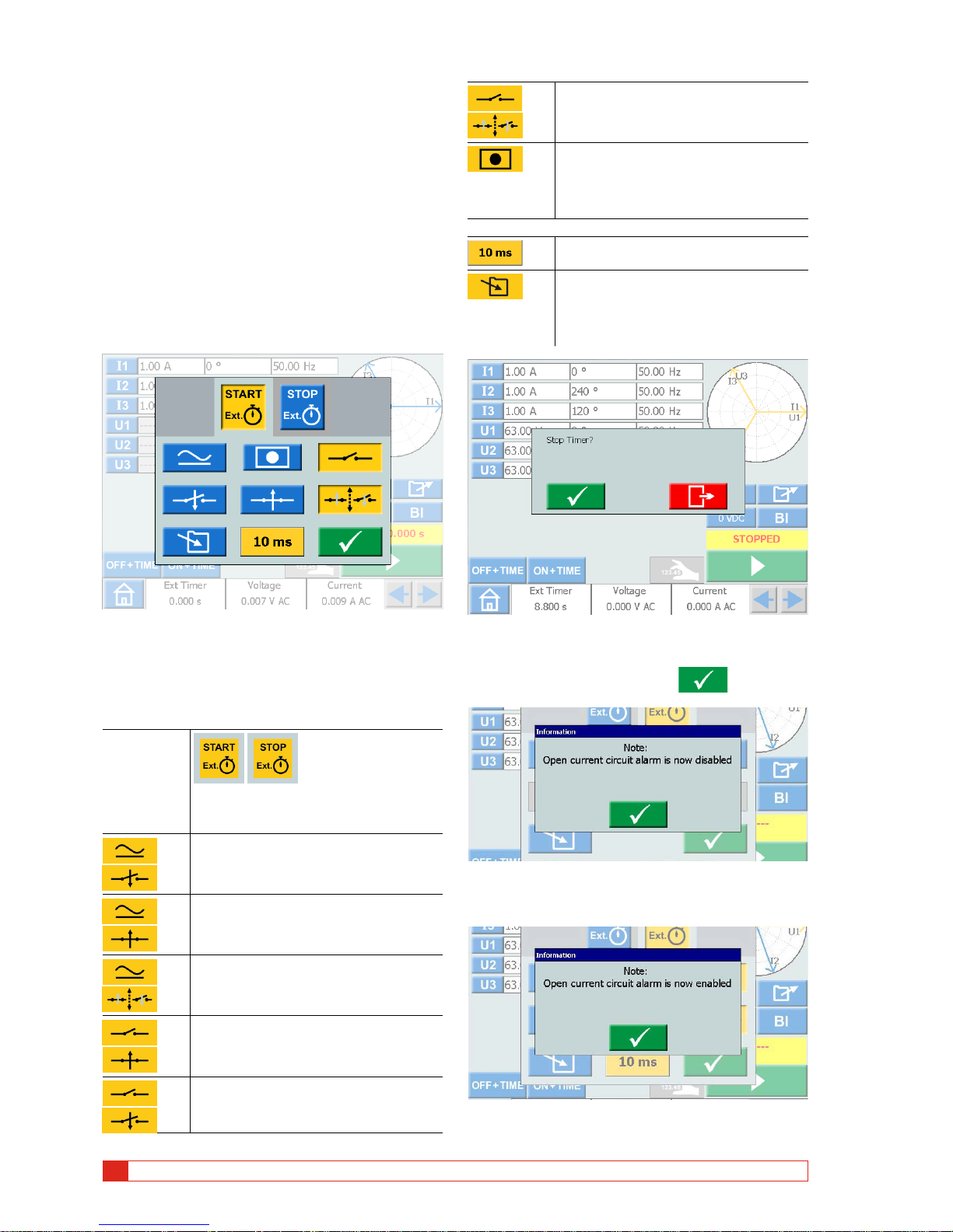
2] Make settings for the START and STOP condi-
tions.
The conditions can be set different for START
and STOP.
Start and Stop conditions
Condition
The settings for starting and stopping
are done independently..
At application of either an AC or DC
voltage.
At removal of either an AC or DC voltage.
At application or removal of AC or DC
voltage.
At the opening of normally closed
contacts
At the closing of normally open contacts
At the opening or closing of contacts.
When a generator is turned on or off,
or that a trip signal stops the generating or that an open current circuit is
detected.
Other functions
Filter time can be set from 0 to 999 ms.
The timer value is stored
Note: The timer value can not be saved
separately only together with a test
made in any instrument.
If the "Ext.timer" has failed to stop, it can be manually stopped and reset.
1] Press "Ext Timer" and then
When internal start and stopp are selected the open
current circuit alarm is disabled.
When one of the internal start/stop settings is removed the open circuit alarm is enabled.
Page 15
CR0333LE ZP-CR02E SVERKER900
15
3 INSTRUMENT DESCRIPTION
3.8 A-meter / V-meter
SVERKER is equipped with an ammeter and voltmeter.
These instruments can also be used to display resistance, frequency, impedance, phase angle, power and
power factor. Moreover, these instruments can be
used to perform measurements in external circuits. In
both cases, the values appear on the display.
The ammeter input (marked “A”) measures 0 – 10 A
(ACrms or DC) in an external circuit.
The voltmeter input (marked “V”) shows the voltage
connected to the voltmeter on the panel. The voltmeter can be used to measure up to 900 V AC or DC. It
can be set in ranges or automatically mode.
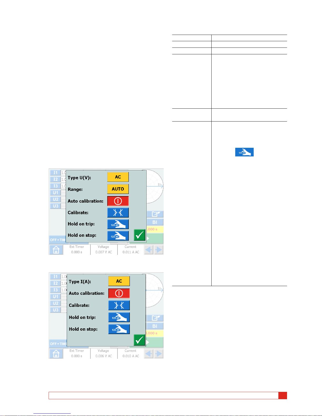
1] Press ”Voltage” or "Current" at bottom of
display, from any of the instruments.
You will see the respective new windows
below.
Voltage
Current
Ammeter and Voltmeter windows
Type U (V) Select AC or DC
Range Auto, 0-9 V, 9-90 V, 90-900 V
Type I (A) Select AC or DC
Auto calibration The auto calibration can be set to
on or off individually (Ammeter/
Voltmeter).
If auto calibration is set to “ON”
it will recalibrate the offset each
10 minutes period and also do an
offset calibration within 5 minutes
if the temperature is changed.
Calibrate The AC and DC offset will be
calibrated.
Hold on trip The value measured on the volt
and / or ammeter is frozen when a
trip signal has been detected. The
"ON+TIME" has to be activated.
1] Press to activate
the HOLD function in the
volt and/or current menu.
The Voltage and / or Current field
turns blue and at trip it turns yellow.
The voltage and current values can
be stored to a test file.
A] In the Main menu, the volt-
age and current values for
pick-up or drop-off, can also
be locked.
B] In the Ramp instrument this
will be valid for a whole
ramp sequence.
C] In the Prefault/fault in-
strument this will be
valid for fault state and
prefault+fault state
Page 16
16 SVERKER900 ZP-CR02E CR0333LE
3 INSTRUMENT DESCRIPTION
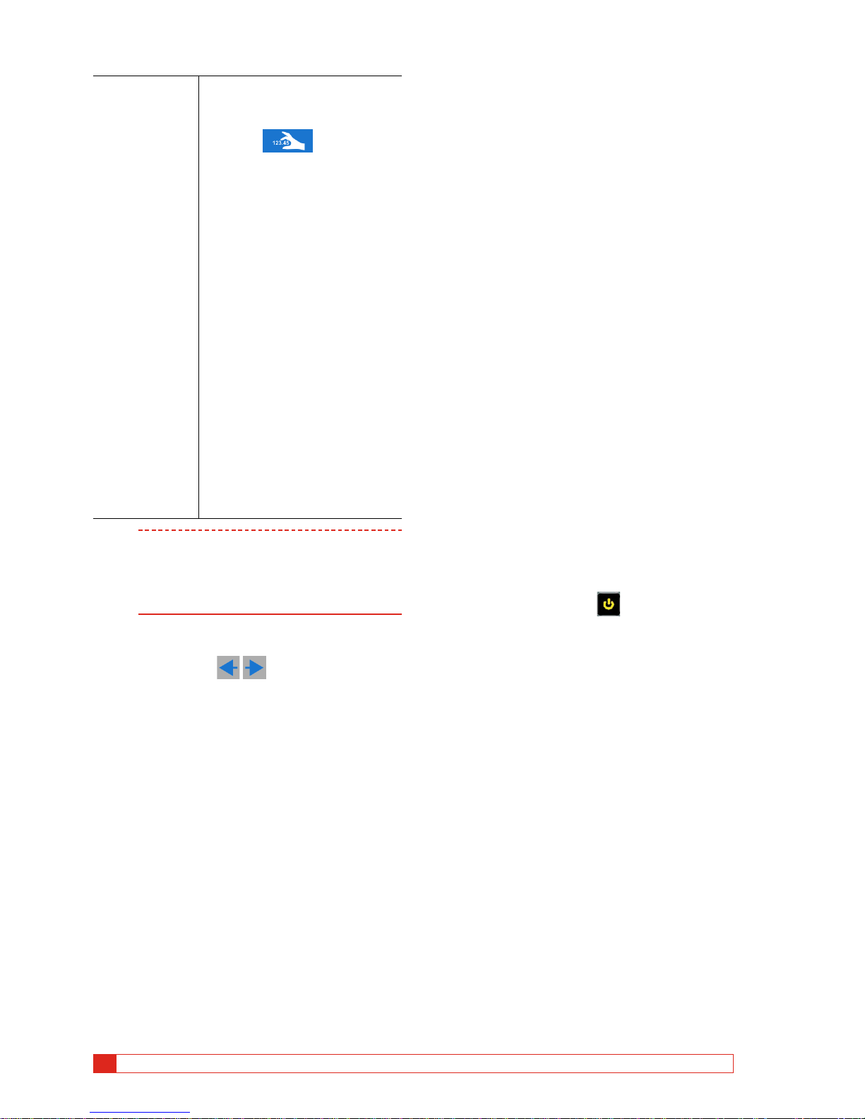
Hold on stop Values from the volt and /or amme-
ter are held after stop of generating.
1] Press to activate
the HOLD function in the
volt and/or current menu.
The Voltage and / or Current field
turns blue and at stop it turns yellow.
The volt and current values can be
stored to a test file.
A] In the Main menu, the volt-
age and current values for
pick-up or drop-off, can also
be locked.
B] In the Ramp instrument this
will be valid for the start
ramp value and for the
whole ramp sequence.
C] In the Prefault/fault instru-
ment this will be valid for
prefault state, fault state
and prefault+fault state
Note If O.L. (Over Load) appears, the cycle being
measured may have been so fast that there
was not time for automatic range changing,
or that the range was overridden.
If over 900 V or 10 A, it gets +OL.
Other entities
1] By pressing the buttons you can view
the Frequency (Hz), Power (VA and W) , Impedance (R and Z) and phase angle values.
3.9 USB port
USB 2.0 Interface
The USB port is used to:
▪
Update the firmware in the SVERKER900
▪ Update the software
▪ Connect a mouse or keyboard
▪ Download test files from the SVERKER900 Local for
transfer data, e.g. to a PC for storage or printing.
▪ Copy test files from USB to SVERKER 900
Firmware upgrade via
SVERKER900 USB port
1] Contact Megger Sweden AB technical sup-
port to get a USB memory stick with upgraded files.
USB software upgrade
1] Before startup, insert USB memory stick, with
new software, to the USB port.
SVERKER 900 scans the available files in the
USB memory. If a bootable image can be
found and the image signature is newer than
the currently installed image, you are asked
to upgrade SVERKER 900.
After loading new software you must reboot.
2] Press and hold (5 s) the button to reboot.
Page 17
CR0333LE ZP-CR02E SVERKER900
17
3 INSTRUMENT DESCRIPTION
3.10 Ethernet port
Note The Ethernet port is used for service of the
instrument only.
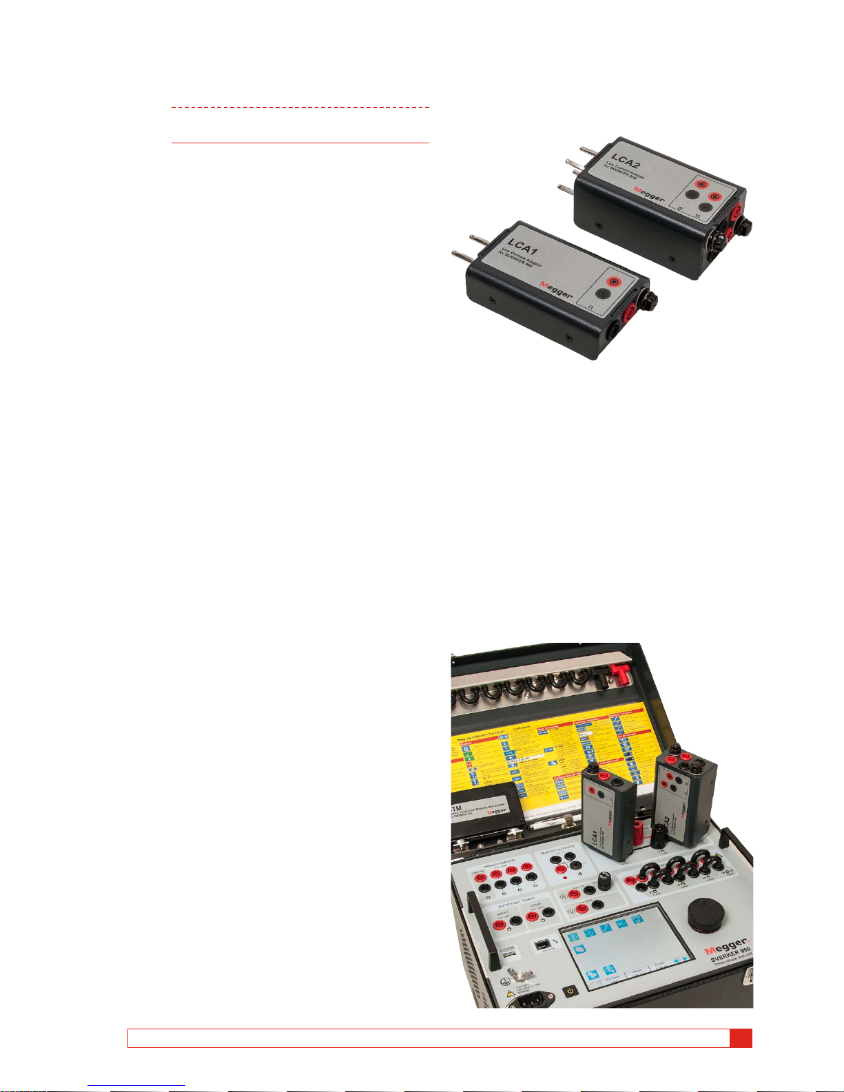
3.11 Low current
generation (Optional)
An optional accessory (CR-91010) is the Low Current
Adapter. The adapter consists of two boxes LCA1
and LCA2. It is used to test e.g. sensitive earth fault
protection, capacitor unbalance protection and three
phase reverse power protection.
The LCA1 and LCA2 are to be connected to the current generator outputs, see figure below, for generation of low currents, 0 – 50 mA. The built in ammeter,
in SVERKER 900, is connected to measure the current
injected into the test object.
The ratio between the input and output currents is
somewhat depending on the load, e.g. a 0.5 Ω load
and 1 A current generation gives an output of 9 mA.
Max current input is 5 A.
Page 18

18 SVERKER900 ZP-CR02E CR0333LE
4 OPERATING SVERKER 900
4
Operating SVERKER 900
4.1 Local interface
The SVERKER900 local interface is the manual control
and user interface for the unit. All manual entries will
be made through the SVERKER900 local interface.
Display buttons
The buttons are of two types, momentary and switch.
Momentary buttons
▪ A momentary button keep the colour when it is pressed.
▪ When it is gray, the button is disabled.
Examples:
Switch buttons
1. When a switch button is pressed the background
colour change from blue to yellow and foreground
change from white to black. – the function is active.
2. A button with gray background is disabled.
• If the foreground is black the function is active,
but you cannot use the button to make changes.
• If the foreground is white the function is disabled.
Examples:
On/Off button
Run/Stop button
Start SVERKER 900
1] Plug the unit line cord into an appropriate
power source and press the button .
During the power up sequence the test system automatically run a self-test to insure everything is operating properly. When this is done the Main instrument
screen is presented. This is the default screen and
depending on how the channels are configured the
SVERKER900 will display and provide the appropriate
number.
From the Main instrument you can perform the general tests with SVERKER, see section "4.3 Main instrument" on page 21
Note The basic description of how to use the
SVERKER is in section "Main instrument". It
also applies to several of the other instruments.
The other instruments are available from the Home
menu.
1] Press for the Home menu
Page 19

CR0333LE ZP-CR02E SVERKER900
19
4 OPERATING SVERKER 900
4.2 Home menu
In Home menu you can:
▪ Select type of test instrument
▪ Select system configuration
▪ Activate already saved test files or download on external
memory (USB)
▪ Select Voltage / Current and External Timer configuration.
This can also be done in all the test menus.
Home menu buttons
Symbol Description
Main instrument
The Main instrument screen is the default screen
for SVERKER 900, and is presented when started.
Prefault -> Fault instrument
Ramping instrument
Sequencer instrument
CT-Magnetization instrument
Impedance instrument
Test file management
System configuration
Configuration of Voltage / Current generators
Browse left/right
System configuration
1] Press for the Home menu
2] Press
▪ Advanced mode
When advanced mode is ON the following functions are
enabled in certain instruments: Harmonics and Event
recording.
▪ Change State On 0-crossing
Setting of how to change state in the Sequencer
instrument.
When “Change State On 0-crossing” is
OFF it
means that the curve form (amplitude, phase, frequency)
is changed immediately if amplitude or phase or
frequency is changed between the different states.
When “Change State On 0-crossing” is
ON it
means that the state is not finished until the curve form of
phase I1 reaches the zero crossing (If I1 is not included in
the test I2 is the master). Then the state is completed.
▪ Hide warning messages
When this setting is OFF
all the warning messages
will be displyed.
When this setting is ON
the warning messages listed
in Troubleshooting section of this User's manual will be
hidden.
▪ IEC / IEEE30 / IEEE45
• IEC – voltage channels will be depicted “U”
Time values will be referenced in seconds and
milliseconds.
• IEEE30 / IEEE45 – voltage channels will be depicted “V”
Time values will be referenced to cycle times.
• The CT instrument can be set for the standards IEC,
IEEE30 or IEEE45.
▪ 50 Hz / 60 Hz / 16 2/3 Hz
Select frequency
The trip times will be based on the selected frequency.
▪ The same is valid when trip results are set to cycles when
IEEE30 or IEEE45 standard is set
Page 20

20 SVERKER900 ZP-CR02E CR0333LE
4 OPERATING SVERKER 900
▪ Versions
About SVERKER 900: year manufactured etc.
▪ Date and time setting
▪ TouchCal
Follow instructions for calibration of touch screen.
If no keyboard is used, press middle of screen when new
calibration is done.
▪ Labels for test files
Setting of four fields for report handling.
Note: The language setting for the volt and ammeter is
shifted when instrument is restarted.
▪ Field calibration
For detailed information and instructions see section
"4.10 Calibration" on page 42.
▪ Language
Czech, English, French, German, Spanish, Swedish
▪ Ext.KeyBoard
Select language for an external keyboard.
▪ License file
To add additional instruments to the SVERKER 900, press
the “License file” button. Insert the USB stick with the
license file and follow instructions on the display.
Generator configuration
1] Press for the Home menu
2] Press
The generators can be configured in three different
connections: individual, serial or parallell. Voltage generators can be used as 3AC+1AUX (AC/DC) or 4AC.
Use the supplied jumpers to make the connections.
See page 12 and page 13.
Generators individual
Generators in serial
Generators in parallel
Use as a fourth generator or as an
auxiliary power source
Select AC or DC
Voltage generator in individual connection 3 AC + AUX DC
Voltage generator in individual connection 3 AC + AUX AC
Voltage generator in individual connection 4 AC
Page 21

CR0333LE ZP-CR02E SVERKER900
21
4 OPERATING SVERKER 900
4.3 Main instrument
The Main instrument screen is the default screen for
SVERKER 900, and is presented when started.
SVERKER 900 will be opened with the settings from
last time it was run.
In the example above all current and voltage generators are
set to work separately. See sections "Current generators
separately" page 12 and "Voltage generators separately
"page 13. for configuration.
Main instrument buttons
Symbol Description
Voltage and current generators
▪ Parameter table rows turns into green for
active generators.
▪ Press parameter to make settings.
OF F +TIME: Current source is turned off. When
a valid trip indication occurs, the yellow Trip time
field shows the trip time and the binary input that
detected the trip signal
ON +T I ME: Current source is activated until the
object being tested has operated. When a valid
trip indication occurs, the yellow Trip time field
shows the trip time and the binary input that
detected the trip signal.
HOLD: Captures voltage or current value at trip
signal.
SAV E Tes t
OPEN Test
0 VDC
U4 - DC/AC: Setting the voltage for the U4
generator
When used as AUX supply in voltage configuration
Measuring: Sets the instrument into measurement mode. To stop measurement mode, press
the button again.
Measurement mode is not settable if Advanced
mode is selected in the system configuration
menu.
BI: Configuration of the binary inputs
Equals values for current, voltage and frequency
Balances the phase angle values
Run
Stop
Returns to Home menu
Non-generating mode
This is the default state for the Main instrument. All
generator outputs are inactive, not generating output.
1] In non-generating mode, you can choose to
activate one or more generators and configure the voltage, current, phase and frequency parameters, for each.
2] Select a parameter to configure, the on-
screen numerical keypad will show up.
Generating mode
Selected generators will be activated.
1] Press
You can manually increase or decrease a selected parameter using the control knob and
observe the output.
2] Press the to set the instrument
to measurement mode. The generator table
change colour and the measured amplitude
values vill be presented.
Note “Off+time”, “On+time” or the pick-up/
drop-off functionality cannot be used.
Page 22

22 SVERKER900 ZP-CR02E CR0333LE
4 OPERATING SVERKER 900
3] To stop measurement mode press
.
Note Any combination of parameters can be se-
lected to be manually operated when generating is on. Press on the desired parameters to
change and turn the control knob.
Press
to stop the output
OFF+TIME
1]
Press
2] Press
3] Press to stop the output. The but-
ton changes to and the timer starts
counting.
4] When a trip has been identified on any of
the binary inputs the sequence is ended,
clock stops and result is displayed.
Picture shows trip on binary input 2 after 3.044 s.
ON+TIME
1]
Press
2] Press
3] When a trip has been identified on any of
the binary inputs the sequence is ended,
clock stops and result is displayed.
Note The configured off delay time period is to be
added before turning off generation.
Numerical keypad
The keypad view always shows up when you select a
configurable parameter on screen but only when the
generators are inactive.
1] Use the on-screen numerical keypad for con-
figuration of test parameters.
2] Use the button to confirm the en-
tered value or the button to abort
and exit.
Equals
When you select to configure the voltage level, current level or the frequency parameter, you will find the
button
1] Enter desired value and press
All three VGs or CGs will be configured with
the same value.
Setting frequency to DC
A]
Press "0" and then twice the to set DC
output on the selected channel.
B] Press "0" and then press twice on the button
to set DC output on all channels.
Balance
When you select to configure the phase angle parameter for a selected generator, you will find the button
1] Enter desired value and press button.
The phase angle between the VGs or CGs will
be balanced by 120 degrees.
Page 23

CR0333LE ZP-CR02E SVERKER900
23
4 OPERATING SVERKER 900
Example:
You configure the UL2 angle to 240 degrees and press
the BALANCE button.
UL1 = 0 deg (= 240 + 120)
UL2 = 240 deg
UL3 = 120 deg (= 240 - 120)
Finding the pick-up and drop-off
value using the hold function
1] Press
2] Press
3] Select parameter(s) by pressing the field(s).
The field(s) turns yellow.
4] Turn the control knob clockwise to increase
parameter(s), value(s).
When a trip signal is detected on a binary
input, the amplitude value is saved and a
pick-up value is obtained.
5] Press again.
6] Turn the control knob anticlockwise to de-
crease parameter(s), value(s).
When a trip signal is detected on a binary
input, the amplitude value is saved and a
drop-off value is obtained.
7] Press to stop the output.
The result is shown on display, the pick-up
and drop-off value and the ratio between
the values.
Note You can return to the result window by press-
ing the yellow or red field above the
button.
When a test is saved the field is red.
When the “condensed” view is selected, only the
generators used are shown. The check box "Condensed" is in bottom of the result window.
Note You can return to the result window by
pressing the yellow field above the
button.
Binary Inputs
The binary inputs are polarity sensitive when used in
voltage DC mode. The continuity indicator will light
if in right polarity and the contact condition is met.
When the BI is set to voltage sense and a DC or AC
signal is applied on the BI contact. A constant light is
seen.
For binary input BI1 the trigger level can be defined
(both from low to high and high to low level change)
when voltage mode are selected. For BI2-BI4 the levels
are fixed.
BI window buttons
Symbol Description
Binary input
BI1. The trigger level can be defined (both from
low to high and high to low level change) when
voltage mode are selected.
BI2 – BI 4. The trigger levels are fixed.
Red dot. Indicates that input is active.
≥1 Indicates that the input is logic connected to
another input with OR function (only in advanced
mode).
& Indicates that the input is logic connected to another input with AND function (only in advanced
mode).
indicates that the input is recording all the
events. (only in advanced mode)
Voltage mode. Detects if voltage is applied or
not.
Contact mode. Detects if circuit is closed or not.
Page 24

24 SVERKER900 ZP-CR02E CR0333LE
4 OPERATING SVERKER 900
Make. Trig when a voltage is applied to the start
input or when a contact is closed.
Break. Trig when a voltage applied to the start
input vanishes or when a contact is opened.
Make / Break . Trig when the state of the input
changes.
BI OFF. Turns off the selected binary input
BI ON. Turns on the selected binar y input
Confirm. Settings are confirmed and window
closes
Make BI settings
The procedure for BI-setting are the same in all menus
except sequence instrument.
1] In Main instrument press
The window shown below appears. Here you can se
how the binary inputs are configured.
2] Press a BI button e.g.
The button turns yellow and settings can be
done.
The small red indicator tells that the BI is active.
The BI setting window is shown. Below is an example
for settings of the binary inputs.
3] Press buttons for desired conditions for each
BI, e.g. Contact or Voltage mode, Make or
Break, or Make/Break.
4] Press to turn off a BI.
The button is greyed out and the red indicator is turned off.
Trig condition
The trig condition for the binary inputs is normally
"OR" logic but you can set two or more of the binary
inputs to a logic “AND” when SVERKER 900 is set to
”Advanced mode” (see "System configuration" on
page 19).
1] Press on BI number button to toggle be-
tween trig logic conditions.
Event recording
If SVERKER 900 is set to ”Advanced mode”, all events
on individual active binary inputs will be recorded during the test period.
Each BI can be set to only event record mode if it shall
not be included in trig condition.
1] Press on BI number button to toggle be-
tween different modes.
2] Recorded events will be displayed on the
screen and can be also saved as test results in
the report.
Page 25

CR0333LE ZP-CR02E SVERKER900
25
4 OPERATING SVERKER 900
Note Event recording is available only in certain
instruments.
Debounce filter
1] Press the "10 ms" button to set the debounce
time.
Set debounce
time
Set pickup
and hysteresis
voltage level
The debounce time for DC voltage can be set from 0
to 999 ms.
For AC voltage the debounce time has to be set to
maximum 5 ms.
Note When set to zero, it actually means 2 – 3 ms. A
debounce time of 0 ms is not a realistic value.
The debounce time means that as soon as a signal
(voltage or contact sense) is detected on the binary
input, SVERKER awaits the set debounce time. If the
signal is active during the whole debounce time the
signal is acknowledged as a valid signal, a “true” trip
signal is confirmed.
Special settings available for BI1
Adjustable threshold voltage
When voltage sense is chosen for BI1, the adjustable
pickup and dropout threshold values can be set
between 5 to 240 V and 0 to 235 V.
1] Press the "10.0 V" button, see picture above,
to set the threshold pickup and hysteresis
value.
Set pickup
value
Set hysteresis
value
Hysteresis voltage
The hysteresis voltage is the difference between the
pickup and dropout threshold voltages. If the pickup
threshold voltage e.g. is set to 48 V and the hysteresis
voltage is set to 5 V, the dropout voltage is 43 V.
1] Press the "10" buttons (see picture above) to
set the hysteresis voltage.
Harmonics
To use the harmonics function SVERKER 900 has to be
set to ”Advanced mode”
1] Press for the Home menu.
2] Press
3] Press button Advanced mode (OFF). It
will change to Advanced mode (ON).
Each individual generator can now be set to
generate a harmonic waveform.
Note When the harmonics is enabled the parameter
table has an orange outline.
Page 26

26 SVERKER900 ZP-CR02E CR0333LE
4 OPERATING SVERKER 900
4] Press on e.g. I1. The harmonics instrument is
shown.
In this example you can see that a fault current at
fundamental frequency with a superimposed third
harmonic of 25% will be injected on generator I1.
Highest possible "Component" to set is 10.
5] Press the button to impose the same
harmonics on the voltage or current channels.
6] Press to turn off a generator.
4.4 Prefault->Fault
instrument
The Prefault->Fault instrument is selected from the
Home menu using the button
Using the Prefault->Fault instrument you configure
two different states for the device, Prefault and Fault.
You can configure and activate both stages individually and make SVERKER 900 execute the test and
automatically change from Prefault to Fault state.
The Prefault state configuration is a valid condition
for the test object, meaning it does not trigger during
operation.
The Fault state is an invalid condition and it will trig
the test object.
Measurement mode, see main instrument, can only
be set in prefault mode.
Prefault->Fault view
Navigation
The Prefault->Fault screen scenario includes two views
to configure the conditions for Prefault and Fault
parameters, respectively. For test mode the third view
"Prefault->Fault" is selected.
Prefault -> Fault instrument buttons
Symbol Description
Prefault
Fault + Time
Prefault-Fault
Page 27

CR0333LE ZP-CR02E SVERKER900
27
4 OPERATING SVERKER 900
Prefault view
1] Press the Prefault button to enter prefault
view.
2] Select generators to be active and configure
the voltage, current, phase and frequency
parameters for each.
3] Set the time duration for how long to gener-
ate the Prefault state before SVERKER 900 is
automatically entering Fault state.
4] Press the button if you want to acti-
vate the selected generators.
Note The time duration condition is not valid,
during this operation, and the generators can
only be turned off by pushing the
button.
Fault view
1] Press the FAULT+TIME button from the
Prefault view, for the FAULT view screen.
Here you can configure the parameters for
the Fault state.
1] Select generators to be active and configure
the voltage, current, phase and frequency
parameters for each.
2] Configure the two timing parameters; the
max time duration, for how long the Fault
state will be generated and the off delay
duration, which is the time period after the
test object has triggered and until the output
generation will be switched off.
Automatic Prefault->Fault button
The third view "Prefault->Fault is selected for the test
mode. No values can be changed.
1] Press the button to generate the
Prefault condition for the set time duration
and then change to Fault state.
The device will generate the Fault state until any of
the following conditions are met:
A] Maximum configured time duration has time-
out
B] Test object trips
C] You press the button
Note The configured off delay time period is added
if condition B is met, before turning off generation.
The phase angle graph
On both screen views, Prefault and Fault, a phase
diagram is displayed which illustrates I and U phase
relationship for both states.
1] Press the graph to make it full screen.
2] Tap on full screen to minimize.
Page 28

28 SVERKER900 ZP-CR02E CR0333LE
4 OPERATING SVERKER 900
4.5 Ramping instrument
The Ramp instrument is selected from the Home
menu using the button
The Ramping test is very similar to the Prefault->Fault
scenario. The difference is that you can configure a
ramping condition, between the Prefault and the Fault
state. This includes the step-changes in voltage, current, phase and/or frequency, as well as the ramping
time duration.
Measurement mode, see main instrument, can only
be set in “Set ramp start” mode.
Ramping view
Navigation
Ramping includes four views; Start, Speed, Stop and
Test mode view. You can navigate back and forth
between these four views, by pressing the respective
buttons.
Ramping instrument buttons
Symbol Description
Set ramp start
Set ramp speed
Set ramp stop
Test mode (initiate a ramp test)
No values can be changed
1] Select the generators to be active and config-
ure the voltage, current, phase and frequency parameters for each.
2] Press to set the preferred start values
in the parameter table. The prefault time can
also be set here.
3] Press to set ramp speed.
Note For the phase angle, the direction is indicated
by setting “-“ or not in the keypad menu.
4] Press to set stop values.
5] To initiate a ramp sequence, press
Start a ramp test
1] In the views "Set ramp start" and "Test
mode" you can start generating by pressing
In "Set ramp start" generating can only be
stopped by pressing
For "Test mode view" the output generating is turned
off if any of the following conditions are met.
A] Pressing the
button
B] The ramping state has reached any end
condition
C] The test object trips
If test object trips, the measured trip time is displayed
on screen.
Speed and Stop ramping set views
The Speed and Stop ramping views are only a configuration views, no output generation can be activated
from these screens. Here you configure the ramping
conditions. This includes the ramping step-changes
for the voltage level, current level, phase angle and
frequency.
Note You have to configure the ramping param-
eters before activating the test.
If the settings for ramping have been sat
wrong, e.g. start and stop settings are in
conflict it is not possible to start a ramp test.
The phase angle graph
The phasor diagram in ramping instrument shows the
I and U phase relationship both for prefault state as
well as the end condition state after ramping.
1] Press the graph to make it full screen.
2] Tap on full screen to minimize.
Page 29

CR0333LE ZP-CR02E SVERKER900
29
4 OPERATING SVERKER 900
4.6 Sequencer instrument
The sequencer instrument is used to test several
conditions in a system, e.g. the automatic recloser.
The sequencer instrument is selected from the Home menu
using the button
Navigation
There are 16 programmable states in the sequence instrument. In each state you can set values for voltage,
current, phase angles, frequency.
The following configurations/changes can be made in
each state.
Sequencer instrument buttons
Symbol Description
Copy or delete state
Go to first / last state
Go forward / backward between states
Activates or deactivates BI for each
state individually
Set the time for selected state.
Set the end of sequence
Make voltage/contact sensing configuration for the binary input
Stop condition for selected state
Set contact condition for the binary
inputs for each state individually
Set position for binary outputs for each
state individually
Edit
Copy selected state
Insert selected state
Page 30

30 SVERKER900 ZP-CR02E CR0333LE
4 OPERATING SVERKER 900
Insert and replace state
Delete state
1] Press to copy/paste, delete/
replace or rename a state.
2] Press to make a copy of the selected
state.
3] Go to the state were you want to insert the
state.
4] Press “ STATE ….. (16) “.
In the picture below, state 4 has been selected. As seen underlined text “State #2 is
copied”.
• Press to insert the state. State #2 will be
inserted as #4 and all higher states will be moved
upwards.
If for example 10 states are used (State 10 is
marked as “END SEQ”) the inserted state will be
added and there will be at total of 11 states.
If there are 16 states (maximum number) the last
state will be lost.
• Press
to insert state #2. State #4 will be
deleted.
• Press
to delete the state.
5] Press to edit the state name, for
example "Prefault 1(16)".
6] Press to set the time (milliseconds).
7] Press button to configure, voltage/
contact sensing, Hysteresis and Debounce.
Note When this is changed in any "state" it will
automatically be valid for all states.
8] Select binary inputs and make the settings.
Voltage or contact sense.
Hysteresis voltage (BI 1 only), see page 25
Debounce filter, see page 25
Page 31

CR0333LE ZP-CR02E SVERKER900
31
4 OPERATING SVERKER 900
9] Press button to activate the
and
10] Press
11] Select binary inputs and make the settings.
Note For setting BI, see explanation in BI menu,
page 23.
12] Press to set a stop condition for the
selected state.
The sequence is terminated when a trip signal is detected in that particular state
13] Press to set the current state to be
the last state in the sequence. It also stops to
step further up to a higher numbered state.
14] Press to set the binary output posi-
tion for each state, see "3.4 Binary Output"
on page 11.
15] Start a sequence by pressing
As soon as the condition for a state has been fulfilled the sequencer goes to next state, irrespective of set time (max time for each state).
The results are shown in new window when any of
the following occurred:
▪
After stop on a trip signal
▪ The sequence is terminated with the stop button
▪ All the states have passed.
When the “condensed” view is selected, only the
generators used are shown.
The check box "Condensed" is in bottom of the result
window.
Note You can return to the result window by press-
ing the yellow or red field above the
button.
When a test is saved the field is red.
Page 32

32 SVERKER900 ZP-CR02E CR0333LE
4 OPERATING SVERKER 900
Note The BO relay has a switching time at opening
or closing of relay contact that is not compensated for. The switching time is normally
around 3 to 4 ms. When doing a sequence
the BO relay will be switched directly after the
change of sequence state. Meaning that the
switching relay time extends this transition
between the states with this 3 to 4 ms.
4.7 CT magnetization
instrument
In the lid is an accessory placed that is to be used for
the CT magnetization instrument.
The CT magnetization instrument is used to determine
the knee point voltage of a current transformer.
In CT-mode SVERKER 900 can generate up to 900 V
by connecting the four voltage generators in series
and 300 V by connecting the four voltage in parallel.
The magnetization can be made manual or automatic
or as a combination, to start in manual mode and
then switch to auto for the demagnetization part. This
method is good to use for the first test on a CT.
CTM-box to be used in serial with volt/ampere meter and CT.
Page 33

CR0333LE ZP-CR02E SVERKER900
33
4 OPERATING SVERKER 900
0
0,2
0,4
0,6
0,8
1
1,2
1,4
1,6
0
50
100
150
200
250
300
350
400
450
500
0 100 200 300 400 500 600 700 800 900 1000
A
VA
V
Voltage generators - Series
VA--4
I--4
0
0,5
1
1,5
2
2,5
3
3,5
4
4,5
5
0
50
100
150
200
250
300
350
400
0 50 100 150 200 250 300 350
A
VA
V
Voltage generators - Parallel
VA//4
I//4
CT magnetization instrument buttons
Symbol Description
Set maximum voltage
Possible in all test modes
Set maximum current
Possible in all test modes
Manual mode for the test
Automatic mode for the test
Set-up
1] From the Home menu you press to con-
figure the voltage generators.
Two configurations are possible to use, 4
generators in parallel (300 V) or serial (900 V)
mode, depending on desired output voltage
and power. See adjacent diagrams for guidance.
2] From the Home menu you press
Select IEC or IEEE(45° or 30°) standard.
3] From the Home menu you press the CT in-
strument button
When the CT instrument is opened, a picture
shows how to connect the voltage output to
the CT.
4] Press to confirm the connection.
The screen will show as below.
Note If the screen will show as below you must
correct your configuration, see step 1 above.
Manual test
1] The default mode is manual mode
If not, press the button.
Page 34

34 SVERKER900 ZP-CR02E CR0333LE
4 OPERATING SVERKER 900
2] You can set limits for maximal voltage and
current if needed. Press the buttons
or and make the settings.
3] Start test by pressing and then slowly
turn the control knob clockwise until knee
point is reached.
Note If the control knob is not turned a knob sym-
bol will pop-up in upper left corner to indicate
that turning should be done.
Note The magnetization can be stopped manually
by turning the control knob back to zero.
4] When the arrow on the control knob symbol
changes direction, from clockwise to anticlockwise, you should start the demagnetization by turning the control knob anticlockwise.
5] Press the control knob repeatedly to plot the
graph during the demagnetization.
The graph is plotted and the knee point with
plotting values presented.
6] Press the diagram to get full screen.
Press again to return.
7] The test is completed and ready to save.
Manual/auto test
1] Start in the same way as for the manual test
2] When the arrow on the control knob symbol
changes direction, from clockwise to anticlockwise, press
3] The demagnetization and plotting will be
made automatically.
4] The test is completed and ready to save.
Auto test
1] Press the button to position
2] Press to start a test.
3] Magnetization starts and when the prede-
fined relationship between voltage and current for the knee-point has been reached the
demagnetization will start.
Page 35

CR0333LE ZP-CR02E SVERKER900
35
4 OPERATING SVERKER 900
The graph is plotted automatically and the
knee point and plotted values are presented.
4] The test is completed and ready to save.
Demagnetization
If the demagnetization is interrupted by e.g. pressing
the button a warning message will be displayed.
Important
Make a couple of magnetization and demagnetization sequences manually before
you continue with the test.
4.8 Impedance instrument
The Impedance instrument is selected from the Home
menu using the button
Using the Impedance instrument you configure
sequence(s) with different states including Fault
state(s) with support for impedance entry mode.
Prefault and Fault state can be configured and activated individually or you can also make SVERKER 900 to
execute the test and automatically/manually change
from Prefault to Fault state.
Navigation
The Prefault->Fault sequence includes two views to
configure the conditions for Prefault and Fault parameters, respectively. For test mode Prefault->Fault and/
or Manual binary search views are selected.
Impedance instrument buttons
Symbol Description
Prefault
Fault + Manual pickup search
Prefault-Fault
Manual binary search
CT direction
Configuration
Advanced configuration
Cartesian diagram
Polar diagram
Reset to factory settings
Important
Following generator configurations are
valid for Impedance instrument. Please
verify your generator configuration before start testing in this instrument.
Page 36

36 SVERKER900 ZP-CR02E CR0333LE
4 OPERATING SVERKER 900
Prefault view
1] Press the button to enter prefault
view.
2] Select number of phases and generators to
be active throughout the test and configure
the prefault voltage, current, phase and
frequency parameters using the knob or
keypad.
Tip!
Voltage, phase and frequency parameters
can be set individually for U4 generator if
it is configured as an AC generator and it
can be used as a reference voltage source
throughout the entire test.
3]
Select CTdirection to be also used throughout the test by pressing the or
button.
4] You can set limits for maximum voltage and
current if needed by configuring Umax and
Imax parameters, respectively. These settings
will be applied to all test modes within this
instrument.
5] Press to activate the selected genera-
tors.
Note The generators can only be turned off by
pressing the button and no timer is
applied in prefault view.
Fault + Manual pickup search view
1] Press the button to enter Fault view.
2] Select the fault type by pushing the
button.
3] Set the fault impedance by configuring R
and X or Z and Φ parameters.
Tip!
Press the
on keypad while setting
the Z parameter to move your test point
by 180 degrees.
Note Fault voltage and current phasors are by
default calculated using 1A constant current method. Moreover for one phase fault
the phasor calculations are by default done
in so called ohm/loop domain. In order to
change these default settings and/or testing
in primary domain press
button and
configure relevant parameters.
Page 37

CR0333LE ZP-CR02E SVERKER900
37
4 OPERATING SVERKER 900
4] Press to select binary inputs and
make the settings.
Note For setting BI, see "Make BI settings" on page
24.
5] Press the button to activate the gen-
erators with calculated fault phasors shown
in this view.
6] During generation the R,X,Z and Φ param-
eters can be selected and changed one at a
time by turning the knob as shown in following picture in order to manually search for
pickups in the impedance plane.
As soon as the configured binary input is activated
the trig is registered. You can continue changing the
above parameters to further evaluate the behaviour of
your test object.
Following figure illustrates a possible scenario for
searching a pickup value.
Note The registered trig will not be saved as test
results.
The generators can only be turned off by
pressing the button and no timer is
applied in fault view.
Prefault – Fault view
1] Press the button to enter Prefault –>
Fault view.
2] Press the button to generate pre-
fault-> fault sequence with your previous
configured settings done in Prefault and
Fault views, respectively or follow the following steps to configure and test a new test
point.
3] Press the button to select the fault
type.
4] Set the fault impedance by configuring R
and X or Z and Φ parameters
Note Fault voltage and current phasors are by
default calculated using 1A constant current
method. Moreover for one phase fault the
phasor calculations are by default done in so
called ohm/loop domain. In order to change
these default settings and/or testing in pri-
mary domain press
button and configure
relevant parameters.
Tip!
Factory default settings can be restored
by pressing the
button following
with pressing the
button
5]
Press the button to generate prefault-> fault sequence.
The device will generate the Prefault state following by Fault state until any of the following
conditions are met:
•
Default Prefault time + Maximum Fault time duration
(1+5 sec) has timeout.
• Test object trips.
• You press the button.
Page 38

38 SVERKER900 ZP-CR02E CR0333LE
4 OPERATING SVERKER 900
The default Prefault and Fault durations can be
changed by pressing the
button and configuring
the relevant settings. Moreover, Off Delay and/or Post
Fault state(s) can be added to the sequence.
Following figures illustrate two possible scenarios
when all the states are configured.
6] The result will be displayed and added to the
result table for relevant fault type
7] Continue testing the next test point by re-
peating step 3 to 6 or move to step 8
8] You can save and/or delete the registered
results in the table by pressing the
and/or the button, respectively.
Note Pressing the
button will save all
your results disregarding which fault type is
selected. However, by pressing the
button only the results for previewed fault
type will be deleted. In order to delete all
available results disregarding which fault type
is selected and to start a new test press the
button.
Manual binary search view
1] Press the button to enter this view.
2] Select the fault type by pushing the
button.
3] Press the button to generate prefault
state.
Important
No Prefault timer is applied in this view
and the generators can only be turned off
by pressing the
button if no more
action is done.
4] Set the fault impedance by selecting and
configuring R and X or Z and Φ parameters
using the knob.
5] Press the knob to apply your settings and
generate the Fault state.
Note Fault voltage and current phasors are by
default calculated using 1A constant current
method. Moreover for one phase fault the
phasor calculations are by default done in so
called ohm/loop domain. In order to change
these default settings and/or testing in pri-
mary domain press
button and configure
relevant parameters.
Page 39

CR0333LE ZP-CR02E SVERKER900
39
4 OPERATING SVERKER 900
The device will generate the Fault state until any of
the following conditions are met:
•
Default (5 s) or the previously configured Maximum
Fault time duration has timeout
• Test object trips
6] The result will be displayed and added to the
result table for relevant fault type.
7] The device will generate again Prefault state
directly after fault state
8] You can press the button to stop the
generators or continue testing the next test
point by repeating step 4 to 7.
Following figure illustrates possible scenario for evaluating the behavior of a test object in different imped-
ance zones.
The Maximum Fault duration can be changed by
pressing the
button and configuring the relevant
setting. No Off Delay and/or Post Fault state(s) can be
added to the sequence in this test mode. To generate
a complete sequence Prefault/Fault view to be used.
9] You can save and/or delete the registered
results in the table by pressing the
and/or the button, respectively.
Note Pressing the button will save all
your results disregarding which fault type is
selected. However, by pressing the
button only the results for previewed fault
type will be deleted. In order to delete all
available results disregarding which fault type
is selected and to start a new test press the
button.
The impedance plane graph
On Prefault-Fault view and Manual binary search view
the impedance plane graph always illustrates your present configured test point together with your previous
test results, if any. Registered trips will be marked by X
and no trips with O.
1] Tap on the graph to make it full screen.
2] Toggle between Polar and Cartesian graph
by pressing or
3] Tap on full screen to minimize.
Page 40

40 SVERKER900 ZP-CR02E CR0333LE
4 OPERATING SVERKER 900
4.9 Test file management
From all instruments you can save any test results or
test configuration in SVERKER 900 persistent storage
or to an external USB memory.
When you save a test the first time you will have to
select where to save the test.
When a second test is to be saved, it will by default be
saved in the previous used test file.
Tip!
In the active windows you can turn the
Control knob to browse lists and press the
knob to select an item.
Buttons in Test file management
Symbol Description
Save test
Open test
Quick save
View
Edit
Save to USB
Open USB
Open test file library
Create new file
Delete test file
Save a test
1] Press to save a test.
If no test file are selected the window below
will be shown: "SELECT TEST FILE FOR STORAGE".
2] Select file by pressing on desired row in table
and press
To save in a new file, see point 5 below.
3] Type in the name of the test and add com-
ments.
If you want to select another file to save the
test, press
4] Press to save.
5] To create a new file, press
Page 41

CR0333LE ZP-CR02E SVERKER900
41
4 OPERATING SVERKER 900
6] Enter the label names.
7] Press to confirm.
Quick save
Note By using this option you can save additional
tests in the same file. The first test in the file
cannot be in quick save mode.
1] Press and press the check box
"Quick save mode".
2] Press
3] After each following test press to
save.
The test are not named but placed in the
same file as the first test.
4] To leave Quick save mode, press
and press, to uncheck, the check box "Quick
save mode.
View and reuse test files
1] Press
From the “STORAGE FILE” and “REFERENCE FILE” all
the test files can be selected and opened. Selected
test will be opened in the instrument that is running.
Note Only tests made for the instrument that is
running can be opened.
Storage file
1] In the "STORAGE FILE"window, press
"SELECT TEST FILE FOR STORAGE" is opened.
2] In "STORAGE FILE" window, press the upper
button to edit the "Test File Header".
3] In "STORAGE FILE" window, press the lower
button to edit test name and com-
ments.
Reference file
In the “REFERENCE FILE” window you can view and
open a test for reuse.
1] In the “REFERENCE FILE” window, press
"SELECT REFERENCE TEST FILE" window is
opened.
2] Select the test file you want to reuse for your
test.
3] Press
In the "REFERENCE FILE"window a list of the tests will
be shown and in the left window "PREVIEW" you can
see the test settings.
4] Select the test you want to reuse and press
The test settings will be uploaded to the running
instrument.
Transfer files to PC
Transfer files to PC for further handling by saving
them to an USB stick.
1] Press for the Home menu.
2] Press to open the "Test file manager".
Page 42

42 SVERKER900 ZP-CR02E CR0333LE
4 OPERATING SVERKER 900
3] Here one or more files can be selected and
copied to an USB stick.
4] Select file by scrolling the list and press the
Control knob, or press on check box to select
a test file.
5] Press the button to save.
Note: The USB buttons are enabled when a USB
stick is connected to SVERKER 900.
The button
opens an edit file menu for the
label data.
The files are saved as ".csv" files in the root directory
on the USB stick.
Selected test file can also be put to the waste bin.
The right most column shows how many tests are
included for each test file.
The csv file can be opened on a PC by double clicking,
or by associate the csv file to be opened in Excel or
Word, or other program.
Copy test files from USB stick to
SVERKER 900
1] Insert a USB stick to the SVERKER 900.
2] Click the button.
The test files on the USB stick are shown and
can be copied to SVERKER 900.
4.10 Calibration
Generally we recommend to calibrate the
SVERKER900 yearly. The parts to calibrate are the
voltage and current generators and the voltage and
ammeter.
Equipment needed:
▪ Digital Multimeter (DMM) with high accuracy. We
recommend the Agilent 34410A or equal.
▪ SVERKER900 calibration box (Art. No. CR-91010).
▪ To make an automatic calibration you will also need
connection via the Ethernet port to a router with DHCP
function or to a switch with network connection.
Calibration procedure
1] In the System Configuration menu, press
In the next menu you can select to do a manual
calibration or an automatic calibration. The automatic
calibration will take about 15 minutes.
Note If you want to save the calibration report to
an USB stick it has to be inserted to SVERKER900 during calibration.
Automatic calibration
The automatic calibration is done by connecting
SVERKER 900 to a DMM (Agilent 34410A or equal)
via a router or a switch. If you use a switch you also
need network connection.
1] To make an automatic calibration the IP ad-
dress for the DMM has to be obtained.
2] Enter the IP number in the “IP Address:”
field.
The TCP port number is by default 5024.
3] Press the button.
4] Connect the router/switch and SVERKER900
according to the picture.
5] Press to confirm.
If the connection between the DMM and the
SVERKER900 succeeded, it is stated in top
Page 43

CR0333LE ZP-CR02E SVERKER900
43
4 OPERATING SVERKER 900
of the menu “Connected to measurement
equipment”.
Now you can proceed with the automatic calibration
of the voltage and current generators and the volt/
ammeter provided the checkboxes are marked for the
specific parts. When a part is calibrated its checkbox
will be greyed out.
6] Press
A connection diagram appears that shows
how to connect for each part.
7] Make the connections.
8] Press
The measurement table menu is shown.
9] Press to start the calibration process.
When the calibration for e.g. U1 is ready it is shown
with a “+” sign for U1 and next calibration will be for
U2.
Manual calibration
In the System Configuration menu, press
1] Press the
2] Select part to calibrate, by pressing desired
part on top of the menu.
3] Press
The connection diagram is shown.
4] Connect the test leads.
5] Press the to continue.
In the picture above, U1 is selected.
6] From the measurement menu press the
to start the calibration of ”U1”.
7] Read out the measured value from the DMM
and use the knob to enter the value.
8] Confirm the entered value by pressing the
knob or the “ >> ” button.
If the values entered before calibration are within
limits, then no calibration will be performed for that
specific range.
For the voltage and current readings only one measurement are taken for each range.
Several readings are taken for the volt/ammeter. Several measurements are taken for each range.
The values entered will be before calibration, values
during calibration and values after calibration. If the
calibration succeeded, there will be a “+” indication beside the U1. If some of the values were out of
limits and the calibration subsequently failed, it will be
marked with a “-“ beside the U1. The specific calibration value that failed is presented on a red background.
The picture below shows the measured values after a
successful calibration of voltage generator 1.
When the calibration has been made the data can be
saved to an USB stick. Using a PC the calibration report can be opened as a Word document or an Excel
sheet.
Calibration report
The front page of the report states the calibration
dates. If the test values during calibration are within
allowed limit, the calibration factors and dates will
remain. The verification dates will be updated.
Page 44

44 SVERKER900 ZP-CR02E CR0333LE
5 TROUBLESHOOTING
5
Troubleshooting
5.1 Problems
Problem Cause Remedy
Outputs
No current or voltage output Channel disabled Activate channel
The thermal cut-out may have tripped
due to an overload
Wait until the unit has cooled
No Binary output Miniature circuit breaker F1 may have
tripped
Check the miniature circuit breaker
Cannot set U4/DC amplitude,
grayed out
Voltage generators are set in parallel or
serial mode(U1 – U4)
Set generators to work separately
BINARY INPUTS
Binary Inputs do not operate Wrong setting in BI menu Check the BI menu, voltage/contact sense open
or closing
Debounce filter time is inappropriate Set the debounce filter time to be appropriate
Harmonics
Cannot set Harmonics SVERKER is in wrong mode Go to system configuration menu and select
“Advanced mode" ON
Voltmeter / Ammeter
Built in ammeter malfunction Fuse F2 faulty Replace F2
Ammeter / voltmeter shows
incorrect values
Wrong settings Check settings AC/DC and ranges
File handling
Cannot copy files to USB
memory
Test file is not checked in “Test file
management”
Check the test files in the "Test file
management"
USB memory not inserted to SVERKER
or corrupted USB memory
Verify the USB memory
EXTRA TIMER
The Extra Timer value is not
saved to test file
The "Save test" button is not marked
in the Extra Timer setup menu
Mark the "Save test" button
START and STOP does not react
on input signals.
Wrong setting for the debounce time Check the debounce time setting
Wrong setting for the START/STOP Check the START/STOP settings menu, voltage/
contact sense open or closing.
Page 45

CR0333LE ZP-CR02E SVERKER900
45
5 TROUBLESHOOTING
5.2 Error messages
Error message Cause Remedy
INTERNAL COMMUNICATION Internal communication error Restart unit, if same error persist con-
tact Megger representative
FAN #1 FAULTY Big upper fan faulty Check fan and if error persists contact
Megger representative
FAN #2 FAULTY Big lower fan faulty Check fan and if error persists contact
Megger representative
FIRMWARE FAULT Internal firmware error Restart unit, if same error persist con-
tact Megger representative
MAX POWER Too high output power demand or power supply
hardware fault
Check the connected load and/or decrease the setting value. If same error
persist contact Megger representative
OPEN CIRCUIT The current output circuit has been disconnected Check connections
SHORT CIRCUIT The voltage output is short circuit connected Check connections
HIGH TEMPERATURE Generator temperature is too high Wait for cooling down process and/or
decrease the connected load
UNCALIBRATED Calibration data not available Restart unit, if same error persist con-
tact Megger representative
SHUTDOWN FAULT Shutdown time for current generator has been
exceeded
Restart unit, if same error persist contact Megger representative
HARDWARE FAULT Current generator hardware fault Restart unit, if same error persist con-
tact Megger representative
EXTERNAL VOLTAGE External voltage connected to voltage generator Check connections and disconnect the
external voltage source
5.3 Warning messages
Warning message
(Alarm indication)
Cause Remedy
DISTORTION
(Flashing LED+Black bold
frame)
Measured output signal differs from the desired
output signal due to high non linear load characteristic or high output power demand.
Check the connected load
MAX POWER
(Red bold frame)
The output power demand has been exceeded Check the connected load and/or
decrease the setting values
HIGH TEMPERATURE
(Red bold frame)
Generator temperature has been exceeded Stop generation, wait for cooling down
process and/or decrease the connected
load
Page 46

46 SVERKER900 ZP-CR02E CR0333LE
5 TROUBLESHOOTING
5.4 Alarms
Distortion alarm
The distortion alarm is activated when the measured
values deviates from the set values for a current or
voltage generator. The alarm is indicated by flashing
LED for the generator in question. Moreover, in all
instruments, except CT and Impedance, the distortion
alarm is shown with a black bold frame around the
generator in question, see example below.
Tip!
You can compare the set values for the
generator with distortion alarm by press-
ing
In the Impedance instrument the distortion alarm can
be shown in three different ways depending active
screen, see examples below.
The alarm is shown with a black bold frame around the
generator in question.
The alarm is shown with a black bold frame around the
calculated values and the generator in question.
Here the alarm is shown with a black bold frame around the
calculated values.
Other generator alarms
A red bold frame with the same style as described
for distortion alarm indicates other generator related
alarms such as max power or high temperature, see
example below.
The alarm is shown with a red bold frame around the generator in question.
Page 47

CR0333LE ZP-CR02E SVERKER900
47
5 TROUBLESHOOTING
A-meter / V-meter alarm
This alarm is activated when the meters have faulty operation and indicated by flashing red color on the meter in
question, see example below.
The alarm is shown with flashing red color on both A-meter
and V-meter.
Page 48

48 SVERKER900 ZP-CR02E CR0333LE
6 SPECIFICATIONS
6
Specifications
Specifications SVERKER 900
Specifications are valid for resistive load, at 170-240 voltage supply and ambient temperature +25°C ±3°C, (77°F ±5.4°F) after 30
minutes warm up time and in the frequency range 10 Hz to 70 Hz.
All hardware data are for full scale values.
Specifications are subject to change without notice.
Environment
Application field For use in high-voltage substations and
industrial environments.
Temperature
Operating 0°C to +50°C (32°F to +122°F)
Storage & transport - 40°C to +70°C (-40°F to +158°F)
Humidity 5% – 95% RH, non-condensing
Altitude (operational)
2000 m (6500 ft)
Shock and vibration IEC 60 068-2-27
Vibration IEC 6006 8-2-6
CE-marking
EMC IEC61326 -1
LVD I EC61010 -1:2010
General
Mains input 100 - 240 V AC, 50 / 60 Hz
Current consumption 10 A (max) Fuse 250 V F10AH
Power consumption 1800 VA (max)
Dimensions
Instrument 350 x 270 x 220 mm (13.8” x 10.6” x 8.7”)
Flight case with
wheels
615 x 295 x 500 mm (24.2” x 11.6” x 19.7”)
Flight case 620 x 295 x 365 mm (24.4” x 11.6” x 14.4”)
Weight 14.9 kg (32.8 lbs) Instrument only
29.0 kg (64 lbs) with accessories and flight
case (with wheels, GD-00185)
23.9 kg (52.7 lbs) with accessories and
flight case (GD-00182)
Display 5.7” LCD Touch screen
Available languages English, French, German, Spanish, Swedish
Measurement section
BINARY INPUTS 1, 2, 3 ,4 and EXTERNAL TIMER Start/Stop
Number 6
Typ e Dry or wet contacts max, 240 V AC or
340 V DC
Galvanic Isolation Galvanically separated
Max measuring time 35 minutes
Debounce filter Settable, 0 to 999 ms
BINARY INPUT 1 Adjustable threshold and hysteresis
Pick-up value
BI1 5 V AC, 6 V DC
BI2-4 and External
timer Star t/Stop
7 V AC, 9 V DC
Timer
Range Inaccuracy
0 – 50 ms ≤ 1 ms
50 – 500 ms ≤ 2 ms
> 500 ms ≤ 1%
Resolution 1 ms
Voltmeter
Measurement method: AC true RMS, DC mean value
Insulation 900 V, 1273 Vpeak
Input rating 900 V
Inaccuracy
Ranges DC
0-1 V ±0.5% of reading + 3 mV
0-10 V ±0.5% of reading + 7 mV
0-100 V ±0.5% of reading + 30 mV
0-900 V ±0.5% of reading + 300 mV
Ranges AC
0-1 V ±1% of reading + 5 mV
0-10 V ±1% of reading + 10 mV
0-100 V ±1% of reading + 50 mV
0-900 V ±1% of reading + 300 mV
Resolution 1 mV
Frequency
Range 10 Hz – 600 Hz
Inaccuracy < 0.01%
Resolution < 10 mHz
Ammeter
Measurement method: AC true RMS, DC mean value
Inaccuracy
Ranges DC
0-200 mA ±0.5% of reading + 2 mA
0-1.5 A ±0.5% of reading + 3 mA
0-10 A ±0.5% of reading + 10 mA
Ranges AC
0-200 mA ±1% of reading + 2 mA
0-1.5 A ±1% of reading + 3 mA
0-10 A ±1% of reading + 20 mA
Resolution 1 mA
Frequency
Range 10 Hz – 600 Hz
Inaccuracy < 0.01%
Resolution < 10 mHz
Extra measurements
Power factor and phase angle measurements
Ranges Resolution Inaccuracy
Power factor cosϕ -0.01 (cap) to 1
to +0.01 (ind)
< 0.01 <0.04
Phase angle (º)
1)
0º - 360º < 0.1º <0.8º
Impedance and power measurement
AC Z(Ω), R(Ω),X (Ω), P(W), S(VA), Q(VAR)
DC R(Ω), P(W)
Range Up to 999 kX (X=unit)
1) Valid with current >1 A and voltage >10 V
BINARY OUTPUTS
Insulation 250 V AC
Current 1 A (max)
Voltage 250 V AC or 120 V DC
Page 49

CR0333LE ZP-CR02E SVERKER900
49
6 SPECIFICATIONS
Generation section
VOLTAGE GENERATORS
Voltage outputs U1, U2, U3 and U4/AUX out
All voltage sources/generators are galvanically separated from each
other and from ground.
Floating common return is made by using jumper connectors
Range
4-phase AC 4 x 300 V
4-channel DC 4 x 300 V
Power
4-phase AC 4 x 125 VA (max)
4-channel DC 4 x 125 W (max)
Inaccuracy 0.03% range + 0.05% of reading
Distortion(THD+N)
1)
< 0.14% typical (0.25% max)
Resolution 10 mV
Phase
Angle range 0º - 360º
Inaccuracy
2)
< 0.5º (at 50 - 60 Hz)
Resolution 0.1º
Frequency
Range 10 Hz - 600 Hz
Inaccuracy
2)
<0.03 % (45 Hz - 66 Hz)
Resolution 1 mHz
1) THD+N: Values at 50/60 Hz, 200 -300 V, ≥1500 Ω load. Measurement band with 22-22 kHz.
2) The specification is valid for resistive load >2000 Ω for voltage
output separately U1,U2, U3 and U4/ DC out.
Voltage generators in single-phase mode, AC or DC
4 Voltage
generators
in parallel:
U1 // U2 // U3 // U4
Voltage Power
(max)
Current
(max)
300 V 375 VA 1.2 A
100 V 300 VA 3.0 A
67 V 300 VA 4.5 A
External load: min. 7 Ω
3 Voltage
generators
in parallel:
U1 // U2 // U3
Voltage Power
(max)
Current
(max)
300 V 312 VA 1.0 A
100 V 250 VA 2.5 A
67 V 250 VA 3.7 A
External load: min. 9 Ω
4 Voltage
generators
in series:
U1 – U2 – U3 – U4
Voltage Power
(max)
Current
(max)
900 V 450 VA 0.5 A
400 V 360 VA 0.9 A
268 V 350 VA 1.3 A
External load: min. 100 Ω
3 Voltage
generators
in series:
U1 – U2 – U3
Voltage Power
(max)
Current
(max)
900 V 350 VA 0.4 A
300 V 280 VA 0.9 A
200 V 275 VA 1.4 A
External load: min. 75 Ω
CURRENT GENERATORS
Current outputs I1, I2 and I3
All current generators are galvanically separated from each other
and from ground
Floating common return, is made by using jumper connectors
Range
3-phase AC 3 x 35 A
At least 15 repetitions: 10 s ON and 20 s OFF
3-channel DC 3 x 35 A
At least 15 repetitions: 10 s ON and 20 s OFF
3-phase AC 3 x 20 A continuous
3-channel DC 3 x 17 A continuous
Power
3-phase AC 3 x 250 VA (max)
3-channel DC 3 x 250 W (max)
Inaccuracy < 0.5 % of reading, in range 0.5A – 35 A
< 8 mA in range 0 A – 0.5 A
Distortion(THD+N)
1)
< 0.13% typical (0.25% max)
Resolution 1 mA
Compliance voltage ≤50 Vrms
Phase
Angle range 0º - 360º
Inaccuracy
2)
< 0.2º (50 – 60 Hz)
Resolution 0.1º
Frequency
Range 10 Hz - 600 Hz
Inaccuracy
2)
< 0.03 % (45 – 66 Hz)
Resolution 1 mHz
1) THD+N: Values at 50/60 Hz, 10-30 A, 0.5 VA load. Measurement band with 22-22 kHz.
2) The specification is valid for resistive load ≤0.08 Ω and I ≥0.15A.
Page 50

50 SVERKER900 ZP-CR02E CR0333LE
6 SPECIFICATIONS
Current generators in single-phase mode, AC or DC
Current generators in parallel: I1 // I2// I3
Current Power (max) Voltage
(max)
Duty cycle
15 A 750 VA 50 V Continuous
45 A 750 VA 16.5 V Continuous
50 A 750 VA 14.7 V Continuous
60 A 600 VA 10 V Continuous
(AC)
105 A 300 VA 2.8 V At least 15
repetitions:
10 s ON and
20 s OFF
Current generators in series: I1 – I2 – I3
Current (max) Power (max) Voltage
(max)
Duty cycle
18 A 625 VA 14 0 V Continuous
With external inductive load. Frequency: max 200 Hz
15 A 625 VA 140 V Continuous
With minimum 3.5 Ω external resistive load. Frequency: max 200 Hz.
Note: Diagram valid for external resistive load.
Optional accessories
Low current adapters LCA1 and LCA2
Dimensions
LC A1 110 x 64 x 28 mm (4.3” x 2.5” x 1.1”)
LCA 2 110 x 64 x 44 mm (4.3” x 2.5” x 1.7”)
Weight 0.2 kg (0.4 lbs)
Input 5 A (max)
Page 51

CR0333LE ZP-CR02E SVERKER900
51
Page 52

52 SVERKER900 ZP-CR02E CR0333LE
INDEX
Index
A
Advanced mode............................................. 19
Alarms ........................................................... 46
A-meter .......................................................... 15
Application or removal of AC or DC voltage .. 11
Auto calibration .............................................. 15
Auto test ........................................................ 34
Auxiliary supply.............................................. 13
B
Balance.......................................................... 22
Binary Inputs............................................. 11,23
Binary Output................................................. 11
BI window buttons ......................................... 23
C
Change State On 0-crossing ......................... 19
Copy test les from USB ............................... 42
CT magnetization instrument ......................... 32
CT magnetization instrument buttons ............ 33
CTM-box ........................................................ 10
Current generators ........................................ 12
D
Date and time setting..................................... 20
Debounce lter .............................................. 25
Demagnetization............................................ 35
Display buttons .............................................. 18
Drop-off .......................................................... 23
Dry contacts Close ........................................ 11
Dry contacts Open ......................................... 11
E
Equals............................................................ 22
Error messages ............................................. 45
Ethernet port .................................................. 17
External Keyboard ......................................... 20
External timer ................................................ 14
F
Firmware upgrade ......................................... 16
G
Generating mode ........................................... 21
Generator conguration ................................. 20
Generator settings ......................................... 21
H
Harmonics ..................................................... 25
Hide warning messages ................................ 19
Hold on trip .................................................... 15
Home menu ................................................... 19
Home menu buttons ...................................... 19
Hysteresis voltage ......................................... 25
I
IEC / IEEE ..................................................... 19
Impedance instrument ................................... 35
Impedance instrument buttons ...................... 35
Instrument description ................................... 10
J
Jumpers ......................................................... 10
L
Labels for test les......................................... 20
Language....................................................... 20
License le..................................................... 20
Local interface ............................................... 18
Low current generation .................................. 17
M
Main instrument ............................................. 21
Main instrument buttons ................................ 21
Make BI settings ............................................ 24
Manual test .................................................... 33
Momentary buttons ........................................ 18
N
No generating mode ...................................... 21
Numerical keypad .......................................... 22
O
OFF+TIME ..................................................... 22
O.L. (Over Load)............................................ 16
ON+TIME ...................................................... 22
P
Panels............................................................ 10
Pen ................................................................ 10
Phase angle graph ........................................ 28
Pick-up........................................................... 23
Prefault->Fault instrument ............................. 26
Prefault -> Fault instrument buttons ............... 26
Page 53

CR0333LE ZP-CR02E SVERKER900
53
INDEX
Q
Quick save ..................................................... 41
R
Ramping instrument ...................................... 28
Ramping instrument buttons.......................... 28
Reference le ................................................ 41
Reuse test les .............................................. 41
S
Safety .............................................................. 6
Safety instructions ........................................... 6
Save a test..................................................... 40
Sequencer instrument ................................... 29
Sequencer instrument buttons....................... 29
Service and support......................................... 9
Setting frequency to DC ................................ 22
Special settings available for BI1................... 25
Specications ................................................ 48
Start conditions .............................................. 14
Start SVERKER 900 ...................................... 18
Stop conditions .............................................. 14
Storage le .................................................... 41
Switch buttons ............................................... 18
Symbols on the instrument .............................. 6
System conguration ..................................... 19
T
Test le management .................................... 40
TouchCal........................................................ 20
Training courses .............................................. 9
Transfer les to PC ........................................ 41
Troubleshooting ............................................. 44
U
Unpack system ................................................ 9
USB port ........................................................ 16
V
Versions ......................................................... 20
View and reuse test les ................................ 41
V-meter .......................................................... 15
Voltage generators ........................................13
Page 54

54 SVERKER900 ZP-CR02E CR0333LE
INDEX
Page 55

Page 56

WWW.MEGGER.COM
Your “One Stop” Source for all your electrical test equipment needs
Megger is a leading global manufacturer and supplier
of test and measurement instruments used within the
electric power, building wiring and telecommunication
industries.
With research, engineering and manufacturing facilities
in the USA, UK, Germany and Sweden, combined with
sales and technical support in most countries, Megger
is uniquely placed to meet the needs of its customers
worldwide.
Megger is certified according to ISO 9001 and 14001.
Megger is a registered trademark.
Postal address:
Megger Sweden AB
Box 724
SE-182 17 DANDERYD
SWEDEN
T +46 8 510 195 00
F +46 8 510 195 95
seinfo@megger.com
www.megger.com
Visiting address:
Megger Sweden AB
Rinkebyvägen 19
SE-182 36 DANDERYD
SWEDEN
▪ Battery Test Equipment
▪ Cable Fault Locating Equipment
▪ Circuit Breaker Test Equipment
▪ Data Communications Test Equipment
▪ Fiber Optic Test Equipment
▪ Ground Resistance Test Equipment
▪ Insulation Power Factor (C&DF) Test Equipment
▪ Insulation Resistance Test Equipment
▪ Line Testing Equipment
▪ Low Resistance Ohmmeters
▪ Motor & Phase Rotation Test Equipment
▪ Multimeters
▪ Oil Test Equipment
▪ Portable Appliance & Tool Testers
▪ Power Quality Instruments
▪ Recloser Test Equipment
▪ Relay Test Equipment
▪ T1 Network Test Equipment
▪ Tachometers & Speed Measuring Instruments
▪ TDR Test Equipment
▪ Transformer Test Equipment
▪ Transmission Impairment Test Equipment
▪ Watthour Meter Test Equipment
▪ STATES® Terminal Blocks & Test Switches
▪ Professional Hands-On Technical and
Safety Training Programs
▪ AUSTRALIA
▪ BULGARIA
▪ CANADA
▪ CZECH REPUBLIC
▪ CHINA
▪ FRANCE
▪ GERMANY
▪ HUNGARY
▪ INDIA
▪ INDONESIA
▪ KINGDOM OF BAHRAIN
▪ KOREA
▪ MALAYSIA
▪ PAKISTAN
▪ PHILIPPINES
▪ POLAND
▪ ROMANIA
▪ RUSSIA
▪ SINGAPORE
▪ SLOVAK REPUBLIC
▪ SOUTH AFRICA
▪ SPAIN
▪ SWEDEN
▪ SWITZERLAND
▪ TAIWAN
▪ THAILAND
▪ UNITED ARAB EMIRATES
▪ USA
▪ VIETNAM
Megger Group Limited
UNITED KINGDOM
Dover, Kent CT17 9EN
ENGLAND
Subject to change without notice. Printed matter No. ZP-CR02E Doc. CR0333LE V12a 2016
 Loading...