

Page 1

SVERKER
750/780
Relay
Test
Unit
User's
Manual
Megger*
1
Art
No. ZP-CD03E
Doc.
CD0795IE
V07
2013
Page 2
Megger
SVERKER
750/780
Relay
Test
Unit
User's
Manual
NOTICE
OF
COPYRIGHT & PROPRIETARY
RIGHTS
© 2013, Megger
Sweden
AB. All
rights
reserved.
The contents of this manual are the property of Megger
Sweden
AB. No part of this work may be reproduced or
transmitted
in any
form
or
by
any means, except as permitted in
written
license agreement
with
Megger
Sweden
AB. Megger
Sweden
AB has made every reasonable
attempt
to ensure the completeness and accuracy of this document. However, the
information
contained in this manual is subject to change
without
notice, and does not represent a commitment on the part of Megger
Sweden
AB. Any attached hardware schematics and technical
descriptions,
or software listings that disclose source code, are for
informational
purposes only. Reproduction in whole or in part to create
working
hardware or software for other than Megger
Sweden
AB products is
strictly
prohibited,
except as permitted by
written
license
agreement
with
Megger
Sweden
AB.
TRADEMARK
NOTICES
Megger®
and
Programma®
are trademarks registered in the U.S. and other countries. All other brand and product names mentioned in this
document
are trademarks or registered trademarks of their respective companies.
Megger
Sweden
AB is certified according to ISO 9001 and
14001.
Postal
address: Visiting address:
Megger
Sweden
AB Megger
Sweden
AB
Box 724 Rinkebyvagen 19
SE-182
17
DANDERYD
SE-182
36
DANDERYD
SWEDEN SWEDEN
T
+46 8 510 195 00 seinfo@megger.com f f
F +46 8 510 195 95 www.megger.com ^ ^
CD0795IE
ZP-CD03E
SVERKER
750/780
Page 3
Contents
1
Safety
6
Symbols
on
the instrument
6
Safety
instructions
6
2
Introduction
8
2.1 Applications
8
Other applications
8
2.2 Design
and
construction
9
3
Description
10
3.1
General
10
SVERKER
750 control panel
10
SVERKER
780 control panel
10
3.2 Current source
11
3.3 Timer
12
Start conditions
12
Stop conditions
12
3.4 Trip indicator
13
3.5 Display
13
3.6 Ammeter & voltmeter
14
3.7
AC
Voltage source
15
3.8 Auxiliary voltage source
15
3.9
Make/Break
contact
16
3.10 Resistor
set
and capacitor
16
3.11
Power
supply
17
3.12 Computer interface
.17
4
Control
panels
18
4.1 Front panels
18
SVERKER
750
18
SVERKER
780
19
4.2 Current source
20
4.3 Timer
21
4.4 Trip indicator
22
4.5 Display
22
4.6 Ammeter & voltmeter
23
4.7
AC
Voltage source
23
SVERKER
750
23
SVERKER
780
23
4.8 Auxiliary voltage source
24
4.9
Make/Break
contact
24
4.10 Resistor
set
and capacitor
25
4.11
Power
supply
25
4.12 Other
26
5
Making
settings
on
the
display
28
5.1 Introduction
28
5.2 Button functions
29
5.3 Direction indicator
29
5.4 The menu system
30
5.5 Test mode
31
5.6 Injection
32
5.7 Ammeter
32
5.8 Voltmeter
33
5.9
O , (p , W ,
VA... (Extra measurement)
33
5.10Timer
34
5.11 Display
34
5.12
Off
delay
35
5.13
0-Level
filter
35
5.14
Save/Recall
36
5.15 Remote control
36
5.16 Language
37
5.17
SW 37
6 How
to
operate
SVERKER
38
6.1
General
38
6.2 Injecting current - General
rules
38
Output
alarm
38
6.3 Selecting the correct current output
39
6.4 Measuring current
39
6.5 Setting
the
desired current
40
6.6 Finding pick-up and drop-out limits for over
current/voltage/other
entity relays
41
6.7 Finding pick-up
and
drop-out limits for under
current/voltage/other
entity relays
42
6.8 Measuring operating times for over current/
voltage/other entity relays
43
6.9 Measuring operating times for under (cur-
rent/voltage/other
entity) relays
44
6.10 Measuring voltage
44
?m
SVERKER
750/780
ZP-CD03E
CD0795IE
Page 4
6.11 Obtaining the correct
phase
angle when
two
or
more
AC
outputs
are
being used ..45
6.12 Generating higher voltages
45
6.13 Setting
an
auxiliary voltage
46
6.14 Testing voltage relays - both pre-fault
and
fault
voltages
46
6.15 Changing the current and voltage
phase
dif-
ference
47
SVERKER
750
47
SVERKER
780
47
6.16 Measuring
the
phase
angle
48
6.17 Measuring external
cycle
time (measure-
ment not initiated
by SVERKER) 49
6.18 Measuring
Z, R R, X, VA, VAR
and
COS
(p. 49
6.19 Plotting a magnetization curve
50
6.20 Testing
an
automatic recloser
50
6.21 Measuring the
trip
pulse length
51
6.22 Injecting current - External start
52
7
Application
examples
54
7.1 Testing voltage relays
54
7.2 Testing over-current relays
55
7.3 Testing directional over-current relay systems
or directional ground-fault (earth-fault)
relay systems
57
SVERKER
780
57
SVERKER
750
58
7.4 Testing power relays
60
7.5 Testing undervoltage relays
61
Test hook-up and
initial
settings
61
7.6 Testing motor overload
releases
and overcur-
rent
cut-outs that grant/deny starting per-
mission
63
7.7 Testing frequency relays
63
8
Troubleshooting
64
8.1
General
'. 64
8.2 Displayed
values
64
8.3 Error
messages
etc 65
9
Specifications
66
Specifications
SVERKER
750/780
66
Specifications extended
67
Maximum load times for different currents....
67
The voltage outputs
of
the current source
67
Separate
AC
voltage source
67
Auxiliary
DC
voltage output
67
Inputs
68
Make/Break
contact
68
Measurement section
68
Extra measurements
69
Other
69
Index
72
CD0795IE
ZP-CD03E
SVERKER
750/780
Page 5
Safety
Symbols
on the
instrument
Caution, refer to accompanying documents.
Protective conductor terminal.
WEEE,
Waste
Electrical and Electronic
Equipment.
Please
utilize your local
WEEE
collection facilities in the dispo-
sition
of
this product and otherwise
observe all applicable requirements.
Safety
instructions
A
A
Important
Read
and comply with the following instructions.
Always
comply with local safety regula-
tions-
Warning
First
of
all, connect protective earth
(ground).
Use
the green/yellow cable.
Never
connect the
SVERKER
750/780
to an
external voltage
if
the protective earth
(ground)
is
not connected.
Always
use safety connecting leads.
Always
turn the
SVERKER
750/780 off
before connecting.
Generated
voltages and currents may
be
harmful
to
the operator
or
the
device
under test.
The
SVERKER
750/780 should
be
operated
only
from the type
of
power source
indi-
cated
on
its nameplate.
The
SVERKER
750/780
is
equipped with
a mains plug having a third
(earthing,
grounding)
pin. This plug will only fit into
an earthing/grounding-type power outlet.
The
SVERKER
750/780 must not
be
used
in
other
ways
than stated
by
the manufac-
turer.
Never
spill water
or
other liquid
of any
kind
on
the
SVERKER
750/780.
Unplug the
SVERKER
750/780 from
the
wall outlet before cleaning.
Use a
damp
cloth
for cleaning.
Do
not
use
liquid clean-
ers
or
aerosol cleaners.
Do not
use
auxiliary equipment not
3
SVERKER
750/780
ZP-CD03E
CD0795IE
Page 6
1 SAFETY
recommended
by
the
SVERKER
750/780
manufacturer since this may
cause
haz-
ards.
Do not attempt
to
service the
SVERK-
ER
750/780 yourself. Opening
or
removing
covers may expose you
to
dangerous volt-
age and other hazards.
Important
For added protection during a lightning
storm,
or
when the
SVERKER
750/780
is left unattended and unused for long
periods
of
time, unplug
it
from the wall
outlet.
This will prevent damage due
to
lightning
and
power line surges.
The maximum load times depends
on the
used current value,
see
chapter 9 under
Specifications extended.
If, for some reason, you need
to
return
your
SVERKER
750/780,
please
use ei-
ther
the original transport box
or
one
of
equivalent strength.
CD0795IE
ZP-CD03E
SVERKER
750/780
Page 7
2
INTRODUCTION
Introduction
2.1
Applications
SVERKER
750/780
is
intended primarily for testing
relay protection equipment, but
it
can also
be
used for
many other purposes. Virtually all single-phase relay
protection
equipment can
be
tested, and
SVERK-
ER
750/780 can also test three-phase relay protection
equipment
that can
be
tested phase
by
phase. Moreo-
ver, many relay protection systems that require phase
shifting
can be
tested.
Items
that
can be
tested
using
SVERKER
750/780 include:
Efficiency tests
Polarity (direction) tests
Type
of
relay
ANSI
standard
code
Overcurrent relay
50
Inverse time overcurrent relay
51
Undercurrent
relay
37
Ground fault relay
SON, 51N
Directional
overcurrent relay
67
Directional
ground fault relay
67N
Overvoltage relay
59
Undervoltage relay
27
Directional
power relay
32
Power
factor relay 55
Differential
protection
(differential
circuit)
87
Distance protection
equipment
(phase
by
phase)
21
Negative sequence overcurrent
relay
46
Motor
overload protection
51/66
Automatic
reclosing devices
79
Tripping
relay
94
Voltage regulating relay
Underimpedance relay
21
Thermal relay
49
Time-delay relay
Frequency relay
(SVERKER
780)
81
Other
applications
Plotting
excitation curves
Current
and voltage
transformation
ratio tests
Burden measurement for relay protection equipment
Impedance measurement
SVERKER
750/780
ZP-CD03E
CD0795IE
Page 8
2.2
Design
and
construction
The current source
built
into
SVERKER
can provide
0-10
A,
0-40
A,
0-100
A,
0-250
V AC or
0-300 V DC. Timing and generation (output) can
be
carried out simultaneously.
When
the relay protection
equipment
trips,
both output and timing
are
inter-
rupted.
Note
The
current output
depends
on the
burden
of
the
relay (circuit).
This
means that
it
is
possible
to
get
high
output currents,
over
the
maxi-
mum
measurement range
of
250
A.
There
is
also a separate
built-in
AC
voltage source
to
supply the relay voltage input.
A 20-220
V DC
voltage source
is
used
to
provide
auxiliary
voltage.
The quality
of
the output signal
is
depending
on the
quality
of
the input voltage.
If
the main voltage
is
distorted
the output signal will also
be
distorted.
However,
the
AC
voltage source
in SVERKER
780
is
fully
synthesized by the instruments itself and there-
fore independent
of
the mains input voltage.
SVERKER is
equipped with a timer, ammeter and
voltmeter,
and these instruments can also
be
used
to
indicate resistance, impedance,
phase
angle, power
and power factor. Moreover, these instruments can
be
used for measurements
in
external circuits.
A set
of
resistors and a capacitor
(SVERKER
750)
are
provided,
and they can
be
connected into the circuits
being tested
to
provide
phase
shifts, fine adjustments
and the like.
A make/break contact can
be
used
to
synchronize
other circuits with tests that are being conducted.
SVERKER
settings are
made
using knobs and other
controls on the control panel. Numerous other settings
can
be
made
via the display window
built
into
the control panel.
CD0795IE
ZP-CD03E
SVERKER
750/780
Page 9
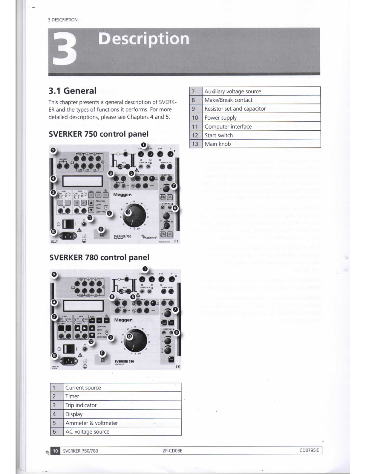
3
DESCRIPTION
Description
3.1
General
7
Auxiliary
voltage source
This chapter presents a general description
of SVERK-
ER
and the
types
of
functions
it
performs.
For
more
8
Make/Break
contact
This chapter presents a general description
of SVERK-
ER
and the
types
of
functions
it
performs.
For
more
9
Resistor
set and
capacitor
detailed descriptions, please
see
Chapters 4 and
5.
10
Power
supply
11
Computer interface
SVERKER
750
control
panel
12
Start switch
13 Main knob
T°~*r|'
• • • •
SVERKER
780
control
panel
1
Current source
2
Timer
3
Trip
indicator
4 Display
5
Ammeter & voltmeter
6 AC voltage source
-
J I SVERKER
750/780
ZP-CD03E
CD0795IE
Page 10
3 DESCRIPTION
3.2
Current
source
The main source
built
into
SVERKER
can
pro-
vide 0-100
A,
0-40
A,
0-10
A,
0-250
V AC or
0-300 V DC,
depending
on
which output
is
used.
As
a rule, this current source
is
used
to
provide simulated
sudden-change fault conditions
for the
object being
tested.
Values
are set
using
the
main knob
on
the
control
panel. Current, voltage
and
other settings appear
on
the
display.
See
section
headed
"Ammeter
and
voltmeter".
Generation
is
turned
on
and off
using
the
start switch
which
has
four positions
Indication
State
Used
to
ON+TIME
Current source
is
activated
until
the
object being tested
has operated.
The
time
is
then displayed, whereupon
SVERKER
returns
automatically
to the
OFF
mode*.
Measure
operating times
for
over-current/voltage/
other entity relays.
OFF
Current source
is
turned
off.
Turn
off the
current
source.
ON Current source
is
turned
on
(acti-
vated).
Make
settings
and
find
pick-up / drop-out
limits.
OFF+TIME
Current source
is
turned
off.
When
the object being
tested
has
operated,
the
time
is
displayed, whereupon
SVERKER
returns
automatically
to the
OFF
mode.
Measure
operating times
for
under-current/volt-
age/other entity relays.
*)
When
trip
occurs, generation
is
interrupted after a number
of
mains cycles. This delay simulates
the
circuit breaker's breaking
time.
The
length
of
delay
can
be set by
the
user.
An indicator lamp
to
the
right
of
the set
of
resistors
is lighted during generation. Generation start-up
is
synchronized with
the
mains, thus eliminating inaccu-
racies
in
the
test results attributable
to
the
instant
at
which
the
start switch
is
activated.
There
are a
number
of
different types
of
generation,
and they
are
selected
via
the
display window (Chapter
5)
Type
of
generation
Explanation
Generation that continues
until
the
object being
tested trips
Generation continues
until
the
timer
stops.
Momentary (manuallycontrolled)
generation
This permits
the
user
to
provide
brief,
manually-controlled genera-
tion
that
is
interrupted immediately
when
the
start switch
is
released.
Time-limited
generation Here,
you
can set a
maximum time
for
generation.
When
it
expires,
generation
is
interrupted immedi-
ately.
Restarted
generation
(used
to
test automatic reclosing
devices)
You
can set
the
SVERKER so
that
generation will
be
restarted (start
again) when
the
timer start input
is activated. This feature
is
used
to
test automatic reclosing devices.
CD0795IE
ZP-CD03E
SVERKER
750/780
Page 11
3 DESCRIPTION
3.3
Timer
Since
the
timer
has a start input and a stop
input,
it
can
be
used
to
measure external
cycles
as
well
as
sequences
initiated
by SVERKER.
The
measured time
appears
in
the
display window.
To test automatic reclosing devices,
SVERKER is
able
to
measure a number
of
sequential time intervals
and
display the results later.
The inputs
can
be
set
individually
to
respond either
to
zero-potential
contact operation
or to a
voltage
(AC
or
DC).
Input
state
indicators
At
each
timer
START
and
STOP
input there
is an
input
state indicator lamp that indicates
the
state
of
the
input.
When
the
indicator lamp
is
lighted,
it
indicates
either a closed circuit (for contact mode)
or
the
pres-
ence
of a
voltage (for voltage mode).
These
indicators
permit
you
to
(for example) check
the
circuits involved
before starting a test sequence.
Start
conditions
The timer
can
be
started
in
the
following ways:
Indication
Start
condition
INT a)
When
an
internal start occurs,
i.e.
for a test
sequence
started
by SVERKER
(ON+TIME
or
OFF+TIME).
b)
When a voltage
is
applied
to
the
start input
or when a contact
is
closed.
c)
When a voltage applied
to
the
start input
vanishes
or
when a contact
is
opened
d)
When
the
state
of
the
input changes.
Stop
conditions
The timer
can
be
stopped
in
the
following ways:
Indication
Stop
condition
INT a)
When
an
outgoing current
is
interrupted
(internal detection).
b)
When a voltage
is
applied
to
the stop input
or when a contact
is
closed.
c)
When a voltage applied
to the
stop input
vanishes
or
when a contact
is
opened.
d)
When
the
state
of
the
input changes.
Measuring
an
external
cycle
Before
measuring,
SVERKER
must
be
set
to the
ON+TIME
state, whereupon
the
timer will also
be
cleared
to
zero.
Clearing
the
timer
The timer will
be
cleared
to
zero when generation
starts again.
Testing
automatic
reclosing
devices
A setting must
be
made
via the
display window before
you
can
test automatic reclosing devices.
ON+TIME
is
lighted
throughout
the
entire cycle. Generation starts
again
each
time
the
timer's start input
is
activated.
SVFRKER
750/780
ZP-CD03E
CD0795IE
Page 12
3.4
Trip
indicator
When
the
stop condition
is
met,
the TRIP
indicator
is
lighted.
This lamp indicates
tripping
of
the
relay
pro-
tection
equipment.
When a test includes
timing,
this
indicator
lamp flashes when
tripping
occurs.
3 DESCRIPTION
3.5
Display
Current,
voltage
and
other entities
can
be
shown
on
the display.
The display window
is
also used
to
make settings.
To
do
this,
you
must
put
SVERKER in
the
setting mode
by
pressing
the
button marked
MODE.
CD0795IE
ZP-CD03E
SVERKER
750/780
Page 13
3 DESCRIPTION
3.6
Ammeter & voltmeter
SVERKER
is
equipped with
an
ammeter
and
voltmeter.
These
instruments
can
also
be
used
to
display resist-
ance, impedance, phase angle, power
and
power
factor.
Moreover, these instruments
can
be
used
to
perform
measurements
in
external circuits.
In
both
cases,
the
values appear
on the
display.
The ammeter measures
one
of
the
following:
• Current
at
one
of
the current outputs 0-100
A,
0-40 A or
0-10
A.
• Current
in an
external circuit connected
to
the
SVERKER
750/760 ammeter panel input (marked
®).
You select
the
desired measurement site (test point)
using
the
button marked
A,
whereupon a indicator
lamp lights
at
the
selected measurement site.
The voltmeter shows
the
voltage connected
to
the
voltmeter
input (marked
V) on
the
panel. This input
is
always
activated.
The ammeter
and
voltmeter both change ranges auto-
matically,
but they
can
also
be
changed manually.
For
AC, they measure true
RMS
value.
You can
change
from
AC to DC
and
vice versa.
Note
When
using
AUTO RANGE
the
measured
value
can be
totally wrong.
This
can
happen
when a previous
value
was in
another range
than
the
present
value.
Set
the
correct
range
(see
section
9.5)
and/or
repeat
the
same
test
again.
A
HOLD
(freeze) function permits
you
to
measure volt-
ages
and
currents having duration
as
short
as a
quar-
ter
of
the mains cycle.
When
the
timer
is
stopped,
the
current
and
voltage values
are
frozen.
If
the timer
is
not
stopped,
the
values present when
the
current
was
interrupted
are
frozen.
The
hold function
is
engaged
by pressing
the
button marked
HOLD.
can
some-
times appear during measurement
of
high-speed
AC
cycles
when
the
hold function
is
invoked. This means
that
no
value could
be
presented
because
the
cycle
was too short.
If
O.F.
(means overflow,
i.e. a
value beyond
the
meas-
urement range) appears,
the
cycle being measured
may
have
been
so
fast that there wasn't time for
automatic range changing.
In
such
case,
you
should
repeat
the
measurement.
The
range-changing system
is memory-equipped,
and
repeating your measure-
ment
may
give
it
time
to
make
the
change properly.
When
current and/or voltage fluctuate widely, a filter
can
be
engaged
to
make reading easier.
The
filter
performs
an
averaging
function.
Instead
of
having current
and
voltage shown
in
amperes
and
volts,
you can
have
them shown
as a
percentage
of a
given current
or
voltage
(the
relay
protection
equipment's setting
for
example). A flash-
ing
current value means that
the
value
is
less
than 1 %
of
the range being used.
To
get a more accurate cur-
rent
reading,
you can
then measure
via the
ammeter
input.
14
SVERKER
750/780
ZP-CD03E
CD0795IE
Page 14
3 DESCRIPTION
3.7
AC
Voltage
source
SVERKER
750
The
AC
voltage source provides 0-120
V AC
(split
into
two
ranges).
It
has two
knobs
of
its own,
one for
rough
and one for
fine settings.
Since
the
AC
voltage
source
is
separated from other outputs,
it is set
inde-
pendently
of
the
current source.
The
AC
voltage source
is
intended primarily for
the
relay protection equipment's voltage input. A set
of
resistors
and a capacitor
can
be
used
to
change
the
phase
angle
of
the
current
and the
voltage.
SVERKER
780
The
AC
voltage source provides 5-220
V AC
with
adjustable phase-angle
and
frequency.
Since
the
AC
voltage source
is
separated from other outputs,
it is
set independently
of
the
current source.
The generated waveform
is
independent from
the
mains
AC
supply
as it is
internally synthesized
by
the
SVERKER
780.
The
AC
voltage source
is
intended primarily for
the
relay protection equipment's voltage input.
Note
For
correct
RMS
readings
the
Ammeter/
Voltmeter
is
automatically
set to the
mains
frequency
at
start
up.
When
the AC
voltage
source
is
switched
on
and
"Frequency"
has
been
selected
as an ad-
ditional
measurement parameter
the
sampling
interval
of the
Ammeter/Voltmeter
is
automat-
ically
set to
measure correctly
at the
selected
frequency
of the AC
voltage source.
In
order
to
supply
an
accurate measurement
for
other
frequencies than
50/60
Hz it
is
nec-
essary
to do the
following adjustment.
1]
Turn
on
the
independent
AC
voltage output.
2]
Enter
the
measurement menu
and
select
Frequency
(U).
3]
Exit
the
menu.
4]
Adjust
to
the
desired frequency.
Note
As
long
as the AC
voltage output
is
turned
on
the
selected
frequency
is
used
for
voltage
and
current measurement.
If
turned
off
the
measurement
returns
to
50/60
Hz.
3.8
Auxiliary
voltage
source
The auxiliary voltage source provides 20-220
V DC
(split
into
two
ranges).
It is
equipped with overcurrent
protection,
and
it is
separate
from
the
other outputs.
Moreover,
it
can
be
used
to
supply
the
relay being
tested.
CD0795IE
ZP-CD03E
SVERKER
750/780
Page 15
3 DESCRIPTION
3.9
Make/Break
contact
There
is a
make/break contact that
is
actuated when
SVERKER
is
set
to
the
ON+TIME
or
OFF+TIME
state.
It
can
be
used,
for
example,
to
synchronize other
equipment
or
to
change
the
voltage supplied
to
the
relay protection equipment
at
the
start
of a
test from
non-faulty
to
faulty
or
vice
versa.
3.10
Resistor
set and
capacitor
The resistor
set and
capacitor
can
be
used
to
change
the
phase
angle
of
the
current
and
voltage.
Note
There
is no
capacitor
on the
SVERKER
780.
The
phase-angle
is
set
with
the
knob
at the
AC
voltage source.
^3 WFRKER
750/780
ZP-CD03E
CD0795IE
Page 16
3 DESCRIPTION
3.11
Power supply
The power supply
is
equipped with a miniature circuit
breaker.
3.12
Computer interface
SVERKER
has a serial port
for
communication with
computers
and the
SVERKER Win
software.
To
be
able
to
use the
SVERKER
750/780 with
the
software
SVERKER Win
the
SVERKER
750/780 must
be
"unlocked" with a software
key.
You
can
check
if
your
SVERKER is
"unlocked"
by
doing
the
following.
1]
Press "MODE".
2]
Press T until
you get
to
the
bottom where
the
SW-version
is
displayed.
If
the
text
"PC-
750"
or "SVERKER WIN" is
shown
the
SVERK-
ER is
"unlocked".
If
the
text
is
not
shown
you
must order
the
software
key for
SVERKER
Win,
(Art.
No:
CD-
81000).
When
ordering
you
must mention
the serial number
of
the
SVERKER
750/780.
CD0795IE
ZP-CD03E
SVERKER
750/780
|
Page 17
4
CONTROL
PANELS
Control panels
1
4.1 Front panels
SVERKER 750
I |
SVERKER
750/780
ZP-CD03E
CD0795IE
Page 18
4
CONTROL
PANELS
SVERKER 780
Page 19
4
CONTROL
PANELS
4.2
Current
source
0
Neutral
For current sources.
1
0-100 A current
output
Regulated
with main knob (7).
2
0-40 A current
output
Regulated
with main knob
(7).
3
0-10 A current
output
Regulated
with main knob (7).
4
Indicator lamp,
ammeter test
point
When
this indicator lamp
is
lighted,
SVERKER is
measuring current
at the
associated output.
To
change
the meas-
urement site,
press
the button marked
A (item 19).
5.
0-250
V, 3 A,
AC
AC voltage
is
variable from
0 to
250
V.
Regulated
with main knob
7.
6.
0-300
V, 2 A,
DC
DC voltage is variable from
0 to
300
V.
Regulated
with main knob
7.
7.
Main knob
Used
to
regulate the current source
(outputs 1,
2, 3, 5
and
6).
8.
Indicator lamp
When
this indicator lamp
is
lighted,
the
current source
is
activated (outputs 1,
2,
3, 5 and 6).
9.
F2 Miniature circuit breaker for the current
source.
4 A
(230
V), 8 A
(115
V).
10.
Rx/Cx
Connector for resistor
or
capacitor.
To obtain a smoother characteristic,
connect one
or
more resistors
in
series.
To
change
the
phase
angle
90° (on
SVERKER
750), connect the capacitor.
Note: A jumper must
be
connected
to
this
connector when
it is
not being used.
11.
Start
switch Turns the current source
on
and off.
Use the • and T buttons
to
select
the
desired mode.
. O ON+TIME
OOFF
OON
OOFF+TIME
V
11
Indication
What
is
meant
ON+TIME
Current source
is
activated
until
the object being
tested has operated. The time
is
then displayed,
whereupon
SVERKER
returns automatically
to
the
OFF
mode.
OFF Current source
is
turned off.
ON Current source
is
turned
on
(activated).
OFF+TIME
Current source
is
turned off.
When
the object
being tested has operated, the time
is
displayed,
whereupon
SVERKER
returns automatically
to
the
OFF
mode.
Button
Function
A
Lights the next higher indicator
lamp (one step up).
•
in
setting mode
(MODE
activated)
Moves
up in
the menu
or
increases
the value.
T Lights the next lower indicator
lamp (one step down).
T
in
setting mode
(MODE
activated)
Moves
down
in
the menu
or
de-
creases
the
value
I
SVERKER
750/780
ZP-CD03E
CD0795IE
Page 20
4
CONTROL
PANELS
4.3
Timer
Indication
Mode
Voltage mode. Detects if voltage is applied
or
not.
Contact mode. Detects if circuit is closed or
not.
Select
either the voltage mode or the contact mode using the
• button (blue). It is the
right
most of the two buttons beneath
STOP
on the control panel.
In the setting mode
(MODE
activated): The • button provides a
move to the
right
on the display.
12.
START
input This is used to start the timer. Max
250
V (AC or DC). The time is shown in
the display
Indication
Condition required
for
timer
start
INT a) Internal.
Used
when
ON+TIME
or
OFF+TIME
is selected.
b)
When
voltage is applied or when a contact
is closed.
-4-
c)
When
applied voltage
vanishes
or when
contact is opened.
d)
When
the state of the input changes.
Select
the desired option using the left most of the two blank-
faced buttons located under
START
on the control panel.
Indication
Mode
Voltage mode. Detects if voltage is applied or
not.
Contact mode. Detects if circuit is closed or
not.
Select
either the voltage mode or the contact mode using the
right
most of the two blank-faced buttons located under
START
on the control panel.
13.
Indicator
lamp
This lamp indicates the state of the
timer
input.
When
this indicator lamp
is lighted voltage is present at the input
(voltage mode) or the circuit is closed
(contact mode).
14.
STOP
input This is used to stop the timer. Max 250
V (AC or DC). The time is shown in the
display.
Indication
Condition required
for
timer
stop
INT
a) Internal.
Used
when
ON+TIME
or
OFF+TIME
is selected.
b)
When
voltage is applied or when a contact is
closed.
-t-
c)
When
applied voltage
vanishes
or when
contact is opened.
-<-+-*-
d)
When
the state of the input changes.
Select
the desired option using the «- button (blue). It is the
left
most of the two buttons located under
STOP
on the control
panel.
In the setting mode
(MODE
activated): The<- button provides a
move to the left on the display.
CD0795IE
ZP-CD03E
SVERKER
750/780
Page 21
4
CONTROL
PANELS
4.4
Trip
indicator
4.5
Display
TRIP
15
This indicates that the object being
tested has tripped. The fact that tripping
occurred indicates that the conditions
imposed
at
the timer's stop input (item
14)
are
met. This indication
does
not
occur unless the object being tested
is
connected
to
the stop input.
A]
Steadily
glowing indicator lamp:
Indicates tripping when the test
is
being
conducted without timing (start switch
at the
ON position).
B] Flashing indicator lamp:
Indicates tripping when the test
is
being
conducted with timing (start switch
at the
ON+TIME
or
OFF+TIME
position).
It
also
indi-
cates
that timing
is
completed.
SVERKER
then
returns automatically
to
the
OFF
state.
You
can reset the flashing indicator lamp
by
press-
ing
the button marked
HOLD
(item 21) twice.
16
123.
H5S
I2.45R
1BH.BV
MODE
17-
ESC
16.
Display
17.
MODE
but-
ton
This button
changes
the display
from
the measurement mode
(normal mode) to the setting
mode and
vice
versa.
Note
In the
setting
mode (MODE activated):
The
ESC
(blue
text)
button leaves
the
present
menu
option
unchanged
and
proceeds
to the
next
higher menu option.
ZP-CDO
SVERKER
750/780
3E
CD0795IE
Page 22
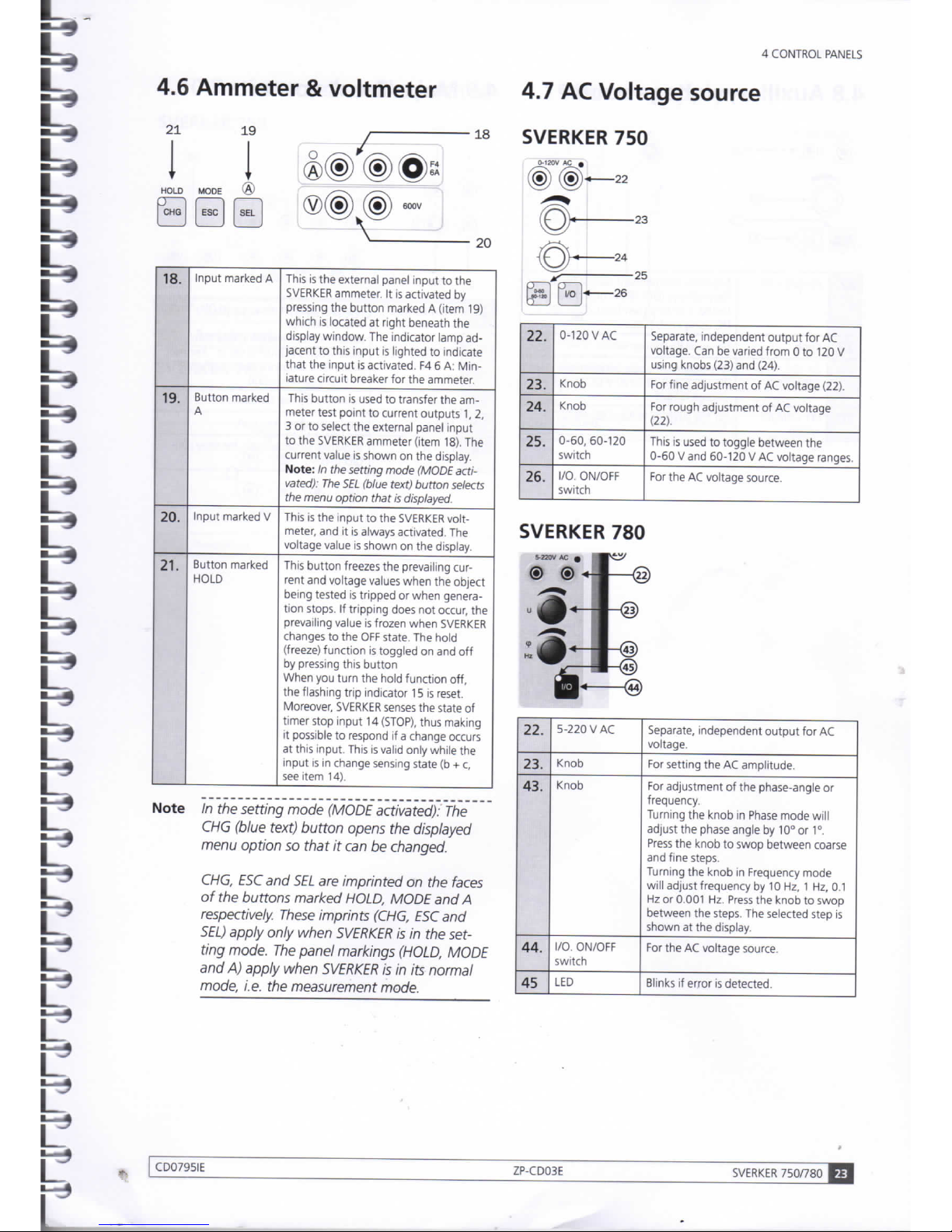
4.6
Ammeter & voltmeter
21
19 , 18
I I
®(§)(D©s
HOLD
P 1
CHG
MODE
® X—x
Esc
g
®(®)
M
^
20
18.
Input
marked
A
This
is
the external panel input
to the
SVERKER
ammeter.
It
is activated
by
pressing the button marked A (item
19)
which
is
located
at
right beneath
the
display window. The indicator lamp ad-
jacent to this input
is
lighted
to
indicate
that
the input is activated.
F4 6 A:
Min-
iature circuit breaker for the ammeter.
19.
Button marked A This button
is
used
to
transfer the am-
meter test point to current outputs 1,
2,
3
or to
select the external panel input
to
the
SVERKER
ammeter (item 18).
The
current value
is
shown
on
the display.
Note:
In the
setting
mode (MODE acti-
vated):
The SEL
(blue
text)
button
selects
the
menu
option
that
is
displayed.
20.
Input
marked
V
This
is
the input to the
SVERKER
volt-
meter, and
it is
always
activated.
The
voltage value is shown
on
the display.
21.
Button marked
HOLD
This button freezes the prevailing current
and voltage
values
when the object
being tested
is
tripped
or
when genera-
tion
stops.
If
tripping does not occur,
the
prevailing value is frozen when
SVERKER
changes
to
the
OFF
state. The hold
(freeze) function
is
toggled
on
and off
by pressing this button
When
you turn the hold function off,
the flashing
trip
indicator
15 is
reset.
Moreover,
SVERKER
senses
the state
of
timer
stop input 14
(STOP),
thus making
it
possible
to
respond
if a
change occurs
at this input. This is valid only while
the
input
is in
change sensing state
(b + c,
see item 14).
Note
In the
setting
mode (MODE activated):
The
CHG
(blue
text)
button
opens
the
displayed
menu
option
so
that
it can be
changed.
CHG,
ESC and SEL are
imprinted
on the
faces
of
the
buttons
marked HOLD, MODE
and A
respectively.
These
imprints
(CHG, ESC
and
SEL)
apply only when SVERKER
is in the
set-
ting
mode. The panel markings (HOLD, MODE
and
A)
apply when SVERKER
is in its
normal
mode,
i.e. the
measurement mode.
4
CONTROL
PANELS
4.7 AC
Voltage
source
SVERKER
750
0-120V
AC 9
(<D(<D
«
22
04
<
26
00
<
26
23
25
22.
0-120
VAC
Separate,
independent output for
AC
voltage.
Can be
varied from
0 to
120
V
using knobs (23) and (24).
23.
Knob For fine adjustment
of AC
voltage (22).
24.
Knob For rough adjustment
of AC
voltage
(22).
25.
0-60,
60-120
switch
This
is
used
to
toggle between
the
0-60 V and 60-120
V AC
voltage ranges.
26.
I/O.
ON/OFF
switch
For the
AC
voltage source.
SVERKER
780
22.
5-220
VAC
Separate,
independent output for
AC
voltage.
23.
Knob For setting the
AC
amplitude.
43.
Knob For adjustment
of
the phase-angle
or
frequency.
Turning
the knob
in
Phase
mode will
adjust the
phase
angle
by 10° or 1°.
Press
the knob to swop between
coarse
and fine steps.
Turning
the knob
in
Frequency mode
will
adjust frequency
by 10
Hz, 1 Hz,
0.1
Hz
or
0.001 Hz.
Press
the knob
to
swop
between the steps. The selected step
is
shown
at
the display.
44.
I/O.
ON/OFF
switch
For the
AC
voltage source.
45
LED Blinks
if
error
is
detected.
CD0795IE
ZP-CD03E
SVERKER
750/780
23
Page 23

4
CONTROL
PANELS
4.8
Auxiliary
voltage
source
4.9
Make/Break
contact
32
33
-27
-28
-29
l/O
-30
27.
20-220
V DC
Separate,
independent output for aux-
iliary
voltage (DC) to the object being
tested.
Can be
varied from
20 to
220
V
DC using knob (28).
28.
Knob For auxiliary voltage (27).
29.
20-130 / 130220
switch
This
is
used
to
toggle between
the
20-130 V and 130-220
V DC
auxiliary
voltage ranges.
30.
I/O.
ON/OFF
switch
For the auxiliary voltage source (27).
31
34
31.
Relay
contact
Changes
state
in
response
to
ON+TIME
and
OFF+TIME.
Note:
Contact switching also takes
place when
SVERKER is
set to
"Reclose"
mode. The
sequence
starts with
the
contact
in
position (33).
32.
Break
(normally-closed)
function.
33.
Make
(normally-open)
function.
34.
F3 1
A
Miniature circuit breaker for relay contact (31).
SVERKER
750/780
ZP-CD03E
CD0795IE
Page 24

4
CONTROL
PANELS
4.10 Resistor
set and
capacitor
SVERKER 750
35
35.
Capacitor
10
mF,
450
V
36.
Resistor
set
SVERKER 780
36.
Resistor
set
4.11 Power
supply
oili
in m
37
39
38
40
37.
Mains voltage
ON/OFF.
38.
Connector
For mains voltage.
39.
F1
Miniature
circuit breaker
for the
power
supply.
4 A (230 V), 8 A
(115
V).
40.
Ground (earth) terminal
CD0795IE
ZP-CD03E
SVERKER
750/780
Page 25

4
CONTROL
PANELS
4.12
Other
41
41.
SERIAL or USB
Serial
port
for
communication with com-
putes
and
the SVERKER Win
software.
Note A driver
for the USB
port
must
be
installed
before
you can use the USB
port.
The USB
driver
is on the
SVERKER
Win CD ROM.
42
42.
Black
dot
Terminals marked with black dots
all
have
the
same
polarity
(used for
AC
volt-
age
sources).
•
SVERKER
750/780
ZP-CD03E
CD0795IE
Page 26

5
MAKING
SETTINGS ON THE DISPLAY
CD0795IE
ZP-CD03E
SVERKER
750/780
Page 27

5
MAKING
SETTINGS
ON THE
DISPLAY
Making
settings
on the
display
5.1
Introduction
There are a number
of
ways
to
make
SVERKER
set-
tings.
In
addition
to
using the buttons and other
controls on the control panel, you
can
make settings
via a menu shown
on
the display.
To
proceed
via
this
menu,
however, you must
first
put
SVERKER in the
setting
mode.
How
to
enter
the
setting
mode
Before
you can change from the measurement mode
(normal mode)
to
the setting mode,
SVERKER
must
be
in
the
OFF
state.
To
enter the setting mode, you press
the button marked
MODE.
Display
shown
in
the
setting
mode
When
SVERKER is in
the setting mode, two lines
ap-
pear
in
the window. The menu heading appears
on
the
first
line, and the selected menu option appears
on the second line between < and > characters.
Menu
heading
<Menu
option>
Memories - Your
default
settings
and
the
original
SVERKER
settings
You can
save
settings that
have
been made
via a
menu.
This can
be
useful when, for example,
you
want
to
prepare settings
in
advance
to
make
it
easier
to
test different types
of
protective relay equipment.
Saved
settings remain
in
the memory
even
after the
SVERKER
has been turned off.
Since
ten memories
are
available for this purpose, you can
save
settings for
up
to
ten different types
of
protective relay equipment.
Each
time
SVERKER is
turned on, the settings
in
memory No. 0 are recalled
as
defaults. Your default
settings,
i.e.
the settings you want to recall automati-
cally
at
turn-on time should thus
be
saved
in
memory
No.
0.
To
save
something
in or
recall something from
a
memory you proceed
via
the
Save/Recall
menu op-
tion.
See
section 5.13.
In addition, there
is a
special memory that contains
the original
SVERKER
settings.
These
can
be
recalled
whenever you want to use them. The original settings
are kept
in
the special memory. They are determined
by Megger, and you cannot change them.
How
to
return
to
the
measurement
(normal)
mode
You can return from the setting mode to the measure-
ment mode
at
any time
by
pressing the
ESC
button.
Note, however, that you may sometimes
have
to
press
this
button twice, depending
on
where you
are in the
menu.
SVERKER
750/780
ZP-CD03E
CD0795IE
Page 28

5
MAKING
SETTINGS
ON THE
DISPLAY
5.2
Button
functions
5.3
Direction
indicator
Injection
<Maintained>
Button
Function
in
setting
mode
(MODE
activated)
CHG Opens a menu option
so
that
it can
be
changed.
If
a numeric value
is to be
changed, a cursor appears
which
can be
moved
by
pressing
the < button
or •
button.
ESC
Leaves
the
menu option unchanged
and
moves
to
menu level 1.
If
you
are
already
on
menu level
1,
pressing
ESC
causes
SVERKER to
leave
the
setting
mode.
SEL
Invokes
the
menu option that
has
been selected.
•
Moves
up in
menu
or
increases a numerical value.
T
Moves
down
in
menu
or
decreases a numerical
value.
•
Moves
right
in
display window.
•4
Moves
left
in
display window.
In addition
to
the
menu heading
and
menu
option,
a
direction
indicator appears
on
the
display.
It
indicates
the direction(s)
in
which
you
can
move
in
the
menu
or
change a numerical value.
The
direction indicator
can
have
one
of
three shapes: diamond (double up/down
arrow),
up
arrow
or
down arrow.
Direction
indicator
I
Injection
A
<Maintained>
Direction
indicator
shapes
and
their
meanings
Indicator
shape
Meaning
t Up
and
down arrow
You
can
move either
up or
down
(or
increase/decrease a value).
•
Up
arrow
You
can
only move
up (or
increase
a
value).
• Down arrow You
can
only move down
(or de-
crease a value).
How
to
change a numerical
value
Some
menu options include numerical values (set-
tings)
that
can
be
changed.
1] To
open a numerical value
for
change,
you
press
the
CHG
button,
whereupon a cursor
appears beneath
the
right
most
digit.
2] You can now
move
the
cursor with
the
-4
or
• button
until
it is
beneath
the
desired
digit.
Then increase
or
decrease
the
value using
the
•
or T
button.
Example:
If
you want
to
change 99.9
to
95.0 you press
the
CHG button
to
open
the
numerical value for change.
Injection
•
Max
time:99.1
s
A
cursor
that indicates which
digit
can be
changed appears
beneath
the
right
most
digit.
Injection
A
Max
time:99.£
s
Press
the •
button
nine
times
to
step
from
99.9
down
to
99.0,
and
then
move
it one
step
to the
left
by
pressing
the
<
button.
Injection
^
Max
time:
95.
0
s
Press
the •
button
four
times
to
step
from
99.0
down
to
95.0.
The
numerical value
is now set as
desired,
but to
invoke
it you
must
press
the SEL
button.
CD0795IE
ZP-CD03E
SVERKER
750/780
29
Page 29

5
MAKING
SETTINGS ON THE DISPLAY
5.4 The
menu
system
Menu
level
1
Menu
level
2 op-
tions
Explanation
Test mode Normal
Measures
time from
START
to
STOP.
Trip + pulse time
Measures
time from
START
to
STOP and
also
the
dura-
tion
of the
trip
pulse.
Reclose:
#01 999
s
Sets
time for reclosing.
Max
49
reclosings.
The
total
time for the specified
number
of
reclosings
can
range from 001
to
999
s.
Injection
Maintained
Generation continues
without
time
limit.
Momentary
Generation continues
while button
is
kept
pressed.
Max time 99.9
s
Generation continues
throughout a preset interval that
can
range from
00.1 s to 99.9
s.
External start
See
section
5.6
Ammeter AC
Measures
AC,
true
RMS.
DC
Measures
DC,
mean value.
Unit:
Ampere
Expressed
in
amperes.
Unit:
% of
nom
I
Expressed
as % of
nominal
current.
Norn
I:
001
A
Used
to set
nominal cur-
rent.
Range:
Auto
Range
selected automati-
cally.
Range:
Low
Fixed
low
range.
Range:
High
Fixed high range.
Voltmeter
AC
Measures
AC,
true
RMS
DC
Measures
DC,
mean value
Shunt (1 -999
mO)
Default shunt value
is 100
mO. Displayed value
is
shown
in A or kA.
Unit:
Volt
Expressed
in
volts.
Unit:
% of
nom
U
Expressed
as % of
nominal
voltage.
Nom
U:
063
v
Used
to set
nominal volt-
age.
Range:
Auto
Range
selected automati-
cally.
Range:
Low
Fixed
low
range.
Range:
Mid
Fixed mid range.
Range:
High
Fixed high range.
Menu
level
1
Menu
level
2 op-
tions
Explanation
Q ,
cp , W ,VA
None
No extra measurement
function
displayed
Z(n.cp)
Impedance (magnitude
+
phase
angle)
Z(Q)
Impedance (magnitude)
R.X(Q. Q)
Resistance
and
reactance
(magnitude
and
magni-
tude)
P(W)
Active power
S(VA) Apparent power.
Q (VAr)
Reactive
power.
cos
<p
Power
factor.
<p(°, Iref)
Phase
difference, current
as reference.
<p(°, Uref)
Phase
difference, voltage
as reference.
Frequency
(U)
Frequency
Timer
Unit:
Seconds
Time expressed
in
seconds.
Unit:
Cycles
Time expressed
in
mains-frequency cycles.
Display
Slow
Average-value
filter
ena-
bled,
thereby stabilizing
the display. 10
values
are
used
to
create
the
average.
Phase
difference
is not
filtered.
Only
for
measure-
ment purpose,
not to be
used
for
time test.
Fast
Average-value
filter
disabled.
Used
always
as
default
for time test.
Hold Trip
Shows
the
max value
in
RMS for
1 period immedi-
ately before
tripping.
Hold
Max
Shows
the
max value
in
RMS for 1
period
within
the
last
0.5 s
held
in
memory.
Hold
Min
Shows
the
min value
in
RMS for
1 period within
the last
0.5 s
held
in
memory.
Off
delay
Cycles
004
Mains-frequency
cycles
throughout
which genera-
tion
is to
continue after
tripping
occurs.
0-Level
filter
1-9
To avoid measuring noise
that
can be
encountered
during
testing. A 0-level
of 1 (min.) allows low-level
signals
to
pass.
AO-level
of 9 (max.) filters
out
most
noise.
|
SVERKER
750/780
ZP-CD03E
CD0795IE
Page 30

5
MAKING
SETTINGS
ON THE
DISPLAY
Menu
level
1
Menu
level
2 op-
tions
Explanation
Save/Recall
Recall
mem
#: 0
Recalls
all settings that
were
stored
in
the speci-
fied
memory.
Range
is
0-3.
Recall
default
Recalls
all
of
the original
settings made
by
Meg-
ger prior
to
delivery (they
are stored
in a
special
memory).
Save
mem
#: 0
Saves
the settings in
the
specified memory.
The
range
is
0-3.
Remote
control
ON Settings
are
controlled
from
SVERKER
Win. This
will
be set
automatically
when Starting
SVERKER
Win.
OFF
SVERKER is
controlled
from
the panel.
Language
English
English language menus,
prompts
etc.
Deutsch
German
language menus,
prompts
etc.
Francais
French
language menus,
prompts
etc.
Espanol
Spanish
language menus,
prompts
etc.
Svenska
Swedish
language menus,
prompts
etc.
SW:
R04E
"PC-750"
or "SVERKER
Win"
Software version.
The
SVERKER is
"un-
locked"
and
ready
to be
used with
SVERKER Win
(or
ProView
PC750
5.5 Test
mode
Test
mode
<Normal>
This menu option
is
used
to
specify the desired type
of
time
measurement. You
have
three choices: Normal,
Trip + pulse time and
Reclose.
Menu
option
Explanation
Normal
Measures
time from
START
to
STOP.
Trip + pulse time
Measures
time from
START
to
STOP
and
also the duration
of
the
trip
pulse.
Reclose:
#01 999
s
Sets
time for reclosings. Max
49
reclos-
ings.
The total time for the specified
number
of
reclosings can range from
1
to
999
s.
1] You
press the
CHG
button
to
access
the
dif-
ferent
memory options, and then scroll
up or
down using the
A or T
button.
2]
Press
the
SEL
button
to
invoke the selected
option.
CD0795IE
ZP-CD03E
SVERKER
750/780
Page 31

5
MAKING
SETTINGS
ON THE
DISPLAY
5.6
Injection
Injection
<Maintained>
Here, you select the type
of
generation.
You
have
four
choices: Maintained, Momentary, Max time and
External Start.
Menu
option
Explanation
Maintained Generation continues without any time
limit.
Momentary
Generation continues while start switch
is
kept
activated.
Max time: 99.9
s
Generation continues throughout a preset
interval
that can
be set
from 00.1
to
99.9
s.
Note:
To change a numerical value,
press
the
CHG
button
one
additional time
and
then
use the
arrow buttons.
External Start
Select
dry
or
wet contact and closing
or
opening
contact for the external signal. This
feature enables you
to
start two
or
more
SVERKERs
simultaneously. The
SVERKERs
"slaves"
can be
connected
to
the make/
break contact
on
the
SVERKER
"master"
and then
be set
for external start. The
slaves
will
start
at
the
same
time
as
the master
(±1 ms).
1]
Press
the
SEL
button
to
invoke the selected
option.
5.7
Ammeter
Ammeter
<AC Amp
Auto>
This option
is
used
to
make settings for the
SVERKER
ammeter.
The ammeter can
be
set
to
measure
AC or
DC.
AC
readings are expressed
as
true
RMS
values while
DC
readings are mean values.
Readings can
be
expressed
in
amperes
or
percentages
of
the nominal current (which can
be
set from 1
to
999
A).
These
choices are called units
in
the menu.
Note
To change a numerical value,
you
press
the
CHG
button
one
additional time
and
then
use
the
arrow buttons.
The range can
be
set
to
Auto
or to
Fixed low
or
Fixed
high.
The fixed ranges are useful for short measure-
ment
cycles
during which the ammeter doesn't
have
time
to
change range automatically.
If
this occurs,
O.F.
(range overflow)
is
displayed constantly.
For more information about the different ranges
see
chapter
9,
headed Specifications.
Menu
option
Alternative
Explanation
AC
Alt.
1
Ammeter measures
AC
as true
RMS.
DC
Alt.
2
Ammeter measures
DC
as mean value.
Unit:
Ampere
Alt.
1.
Current
is
shown
in
amperes.
Unit:
% of
nom
I
Alt.
2.
Current
is
shown
as %
of
the nominal current
which
can
range from
1
to
999
A.
Nom
I:
001
A
—
Nominal current setting
Range:
Auto
Alt.
1.
Range
selected auto-
matically
Range:
Low
Alt.
2
Fixed low range
Range:
High
Alt.
3.
Fixed high rang
1]
Press
the
SEL
button
to
invoke the selected
option.
SVERKER
750/780
ZP-CD03E
CD0795IE
Page 32

5.8
Voltmeter
Voltmeter
<AC
Volt
Auto>
This option
is
used
to
make settings for the
SVERKER
voltmeter.
The voltmeter can
be
set
to
measure
AC or
DC.
AC
readings
are
expressed
as
true
RMS
values while
DC
readings are mean values.
Readings can
be
expressed in volts
or
percentages
of
nominal
voltage (which
can be
set from 1
to
999
V).
These
choices
are
called units
on
the menu.
Note
7b change a numerical value,
you
press
the
CHG
button
one
additional
time
and
then
use
the
arrow
buttons.
The range can
be
set
to
Auto
or to
Fixed low, Fixed
mid
or
Fixed
high.
The fixed ranges are useful for
short
measurement cycles during which the voltmeter
doesn't
have
time
to
change range automatically.
If
this
occurs,
O.F.
(range overflow)
is
displayed con-
stantly.
For more information about the different ranges
see
Chapter
9,
Specifications.
Menu
option
Alternative
Explanation
AC
Alt.
1.
Voltmeter
measures
AC
as true
RMS
DC
Alt.
2
Voltmeter
measures
DC
as mean value
Shunt 1-999
mO
Value
is
shown
as A or kA
Unit:
Volt
Alt.
1.
Voltage
is
shown
in
volts
Unit:
% of
nom
U
Alt.
2.
Voltage
is
shown
as a %
of
the nominal voltage
which
can
range from
1
to
999
V.
Nom
U:
063
V
—
Used
to set the nominal
voltage.
Range: Auto
Alt.
1.
Range
selected automati-
cally
Range:
Low
Alt.
2.
Fixed low range
Range:
Mid
Alt.
3.
Fixed mid range
Range: High
Alt.
4
Fixed high range
1]
Press
the
SEL
button
to
invoke the selected
option.
5
MAKING
SETTINGS
ON THE
DISPLAY
5.9
fif
cp,
Wf
VA... (Extra
measurement)
Q,
(p,
W, VA. . .
<None>
Here, you can select extra measurement functions
(in
addition
to
the voltage and current functions)
For all extra measurement functions,
SVERKER
must
be set for
AC
measurement,
i.e.
for
AC
Amp
and
AC Volt. However, this does not apply
to
the meas-
urement
of
resistance
or
active power. For these,
DC
measurement can also
be
used.
Either voltage
or
current can
be
used
as a
reference
for
calculating the phase difference (phase angle)
between current and voltage.
Then,
when
SVERKER is
used
in
the generation mode
(normal
mode), the selected extra measurement func-
tion
is
displayed
at
the top
of
the window, beside the
time.
Only one option
can be
selected
at a
time.
Menu
option
for
A AC / V AC
(AC measurement)
Explanation
None No extra measurement function
displayed
Z (0.
°)
Impedance and phase angle displayed
Z(Q) Impedance displayed without phase
angle
R, X
(Q,
Q)
Resistance and reactance displayed
P(W)
Active power displayed
P(VA)
Apparent power displayed
Q (VAr)
Reactive
power displayed
cos (p
Power
factor displayed
<p(°. Iref)
Phase
difference displayed with cur-
rent
as
reference
<P
(°,
Uref)
Phase
difference displayed with
volt-
age
as
reference
Frequency
(U)
Frequency displayed
Menu
options
for A DC
/VDC
(DC measurement)
Explanation
No choice No extra measurement function
displayed
R(O)
Resistance displayed
P(W)
Power
displayed
Menu
options
for A DC
/
V AC
or A AC /
V DC
(mixed
measurement)
Explanation
No choice No extra measurement function
displayed
1]
Press
the
SEL
button
to
invoke the selected
option.
CD0795IE
ZP-CD03E
SVERKER
750/780 33
Page 33

5
MAKING
SETTINGS
ON THE
DISPLAY
5.10 Timer 5.11 Display
Timer
<Unit:
Seconds
Here you select the
unit
in which the time displayed in
the
window by the timer is expressed. Time measure-
ments can be expressed in seconds (s) or in mains-
frequency
cycles.
Menu
option
Alternative
Explanation
Unit:
Seconds
Alt
1. Time expressed in
seconds
Unit:
Cycles
Alt
2. Time expressed in
mains-frequency cycle
1]
Press
the SEL
button
to invoke the selected
option.
Display
<Slow>
If
the values shown on the display become unstable
as measurement proceeds, you can
filter
them. Filter-
ing
is accomplished by averaging, and it affects all
displayed values.
Extra measurement functions such as R and X can
now
be calculated after finishing a test (after a
HOLD
trip).
Menu
option
Explanation
Slow
Average-value
filter
enabled, thereby
stabilizing
the display. 10 values are used
to
create the average.
Phase
difference
is not
filtered.
Only for measurement
purpose,
not to be used for time test.
Fast
Average-value
filter
disabled.
Used
always as default for time test.
Hold
Trip
Shows
the max value in RMS for 1 pe-
riod
immediately before
tripping.
Hold
Max
Shows
the max value in RMS for 1
period
within the last 0.5 s held in
memory.
Hold
Min
Shows
the min value in RMS for 1 period
within
the last 0.5 s held in memory.
1]
Press
the SEL
button
to invoke the selected
option.
SVERKER
750/780
ZP-CD03E
CD0795IE
Page 34

5
MAKING
SETTINGS
ON THE
DISPLAY
5.12
Off
delay
Off
delay
<004
Cycles>
This
is
used
to
set the
time, expressed
in
mains-fre-
quency
cycles
throughout which generation
is to
con-
tinue
after
tripping
occurs.
The
range
is
0-999 cycles.
The original Megger setting
is 4
cycles.
If no
delay
is
desired,
set the
number
of
cycles
to 0.
Note
To change a numerical value,
press
the CHG
button
one
additional time,
and
then
use the
arrow
buttons.
Range:
000-999.
1]
Press
the
SEL
button
to
invoke
the
selected
option.
5.13
0-Level
filter
0-Level
filter
<l=Min,
9=Max>
To avoid measuring noise that
can
be
encountered
during
testing,
SVERKER
features a well-defined lower
limit
called
the
0-level.
When
testing ground fault protection (for example)
using
low
currents, this
difficulty
could arise
in
cases
where test values were below
the
0-level.
The 0-level
can be
set
between
1 and
9. A
0-level
of
1
(min.) allows low-level signals
to
pass. A 0-level
of 9
(max.) filters out most noise. A 0-level
of 5 is
the
same
as
the
level provided
in
the
previous version.
CD0795IE
ZP-CD03E
SVERKER
750/780
Page 35

5
MAKING
SETTINGS
ON THE
DISPLAY
5.14
Save/Recall
<Settings>
The settings made under the headings/options discussed
above
can
be
saved
in a
memory where they
will
remain
even
after
SVERKER
has been turned off.
Then when you want
to
conduct a similar test again,
they can
be
recalled from the memory
in
question.
There are four such memories.
Each
time
SVERKER is
turned on, the contents
of
memory No.
0 are
recalled
as
defaults. You can, how-
ever,
recall and use the contents
of
any other memory
by specifying its number
in
this menu.
In addition, there
is a
special memory that contains
the original
SVERKER
settings, and thy can
be
recalled
whenever you want
to
use them.
Menu
option
Explanation
Recall
mem
#:
Recall
settings from the specified
SVERKER
memory (range
is
0-3)
Recall
default:
Recall
the original Megger settings from
the special memory
Save
mem
#:
Save
the settings
in
the specified
SVERKER
memory (range
is 0-3
1]
Press
the
SEL
button
to
invoke the selected
option.
5.15
Remote
control
Remote
control
<OFF>
Together with the
PC
software
SVERKER Win
you
can
control
the settings (except the dials) from the com-
puter.
When
SVERKER Win is
started, the
text
"Remote
Con-
trol"
will appear on the display.
q£ I SVERKER
750/780
ZP-CD03E
CD0795IE
Page 36

5
MAKING
SETTINGS ON THE DISPLAY
5.16
Language
Language
<English>
Here,
you
select
one of
five languages
in
which
the
menus, prompts etc. will appear.
Menu
option
Explanation
English
English-language menus, prompts
etc.
Deutsch
German-language menus, prompts
etc.
Francais
French-language menus, prompts
etc.
Espanol
Spanish-language menus, prompts
etc.
Svenska
Swedish-language menus, prompts
etc
1]
Press
the SEL
button
to
invoke
the
selected
option.
5.17
SW
SW: R04D
This enables
you to
display
the
software version
and
hardware version.
The
user cannot change this
infor-
mation.
Menu
heading
Explanation
sw
Software version
you are
using.
Note
If you
have "unlocked"
the
SVERKER
using
the
"software
key" for
SVERKER
Win,
this
is
shown
with
the
text
"PC-750"
or
"SVERK-
ER
Win" in the
"Software version" window
in
the
menu tree.
CD0795IE
ZP-CD03E
SVERKER
750/780
I
Page 37

6
HOW TO
OPERATE
SVERKER
6
How
to
operate
SVERKER
6.1
General
This chapter presents the steps you should take
to
perform
typical
SVERKER
testing operations efficiently.
Sometimes
several
alternative
ways
of
carrying out
a
step
are
presented. This chapter will help you
formu-
late testing procedures for different types
of
protective
relay equipment.
6.2
Injecting
current - General
rules
When
you inject current through protective relay
equipment for testing purposes, you must observe
several
rules
of
thumb:
•
Provide
as
much impedance
as
possible
in
series
with
the load.
This will counteract changes
in
current and
mini-
mize waveform distortion for relays whose imped-
ances
change when they
have
operated, and also
for
relays that become saturated.
Moreover, the current become more
easy
to adjust,
since this will increase the turn
of
the knob.
•
When
you
are
measuring operating times, the value
of
the applied current
or
voltage used for testing
must exceed the tripping
limit
by an
ample margin
(rule
of
thumb:
1.2-1.5
times the pick-up
limit).
• High current should
be
injected through the protec-
tive relay equipment for
as
short a time
as
possible
to
prevent overheating.
It
may
be
advisable
to
use manually-controlled
(momentary) generation
or
time-limited generation
when injecting high current.
Output
alarm
If
more than 1 V/ 0.5 A flows (in the 10 A range)
when
SVERKER is in
the
OFF
state there will
be a
mes-
sage
on
the display
"CAUTION
OUTPUT".
CAUTION
OUTPUT
SVERKER
750/780
ZP-CD03E
CD0795IE
Page 38

6
HOW TO
OPERATE
SVERKER
6.3
Selecting
the
correct
current
output
Select
the output
at
which the setting knob must
be
turned the furthest
to
obtain the desired current. This
will
improve setting
accuracy
and enable
SVERKER to
deliver maximum power.
When
the object being tested has high impedance
or
may
reach
saturation,
it is
especially important
to use
the output having the highest possible voltage. This
will
drive the desired current through the object being
tested efficiently and minimize distortion
of
the cur-
rent waveform.
6.4
Measuring
current
The ammeter
in SVERKER
has four inputs.
Three
of
them
are
internal inputs fixed
to
the individual current
outputs,
and one
is an
external input located
on the
control
panel. Active input (i.e. ammeter test point)
is
indicated
by an
indicator lamp.
Use the button marked
A to
transfer the ammeter test
point
to
the selected input.
®
SEL
The internal inputs
are
used
to
measure
the current
generated
by SVERKER.
The external input
is
used
to
measure
current in
an
external circuit.
If so
desired,
however,
it
can
be
used for measurement
of
current
from
SVERKER.
This
is
useful
since
ammeter
accuracy
is highest when measurement proceeds via the external input. The external input can
be
used for currents
of
up to
6 A.
The
HOLD
(freeze) function
makes
it
possible
to
measure
currents
of
very short duration. Activate
it
by pressing the button marked
HOLD.
Seethe
section
headed
"Ammeter and voltmeter"
in
Chapter
3.
HOLD
CT
1
CHG
CD0795IE
ZP-CD03E
SVERKER
750/780
39
Page 39

6
HOW TO
OPERATE
SVERKER
6.5
Setting
the
desired
current
1]
Connect the object being tested
to a
suitable
output
on SVERKER.
2] Use
the button marked
A to
transfer the
am-
meter test point
to
the selected current out-
put
or to
the external ammeter panel input.
3]
Activate
ON
using the start switch.
O
ON+TIME
OOFF
frl
00"
I J O
OFF+TIME
4]
Adjust the current using the main knob.
The current can
be
read from the
SVERKER
display.
High
currents
High currents may overheat both the object being
tested and
SVERKER.
You can prevent overheating
by generating currents
of
very short duration. Short-
duration
currents can
be
read very easily using
the
ammeter's
HOLD
(freeze) function.
The best
way to
generate short-duration currents
is to
use manually-controlled (momentary)
or
time-limited
generation.
See
explanation
of
settings
in
Chapter
5.
1]
Connect the object being tested
to a
suitable
output.
2] Use
the button marked
A to
transfer the
am-
meter test point
to
the selected output.
3]
Activate the
HOLD
(freeze) function.
4]
Activate
ON
briefly using the start switch.
5]
Read
the current.
6]
Repeat,
starting with step 4,
until
the correct
current
is
set.
Low
currents
and
good
setting
resolution
You can obtain low currents and good setting resolution
by
connecting one
or
more
of
the resistors
in the
SVERKER
set
of
resistors
in
series
in
the current circuit.
You
can
also use these resistors
to
create a voltage
divider,
thereby reducing the output current.
Limiting
resistors can also
be
connected into the
pri-
mary side (terminal
Rx/Cx)
of
the output transformer.
More-over,
if
you want
to
limit
the current without
generating heat, you can connect the
SVERKER ca-
pacitor (only
SVERKER
750), al-though this will change
the
phase
angle
of
the current.
Sometimes
it is
advantageous
to
use the 0-100
A
output
when you want low currents since
it
has the
lowest output voltage. This low voltage will drive
a
lower current than any
of
the other
SVERKER
outputs
through a high-ohm load
or
series resistor.
[®© (§)
@a
Always
use the ammeter input for external measure-
ment when measuring low currents since
it
provides
the best accuracy.
m SVERKER
750/780
ZP-CD03E
CD0795IE
Page 40

6
HOW TO OPERATE SVERKER
6.6
Finding
pick-up
and
drop-
out
limits
for
over
current/
voltage/other
entity
relays
Method
1a:
Normal
injection,
gradual
increase
in
current.
Current
is
generated continuously. This procedure
is suitable
in
situations where there
is
little
risk
of
overheating the protective relay equipment and
you
wish
to
measure
the drop-out function without using
a second test procedure.
1]
Initial settings:
OFF.
Main knob
at 0.
2]
Connect the
relay's
current input and
trip-
ping
output
to SVERKER.
3] Use
the button marked
A to
transfer the am-
meter test point
to
the selected output.
4] Set
the timer stop condition
(to CLOSURE +
OPENING,
CONTACT
for example).
5]
Activate
ON
using the start switch.
6]
Turn
up
the current
until
the relay operates
(pick-up).
7]
Read
the current.
8]
Turn down the current.
Read
the current that
flows when drop-out takes place.
9]
Interrupt output
by
setting the start switch
to
OFF.
Method
1b:
Normal
injection,
pick-up
and
drop-out
values
obtained
using
the
HOLD
(freeze)
function
Increase
the current gradually
until
the relay operates,
whereupon the current reading
is
frozen. You
can
then start reducing the current immediately, and
the
current reading will
be
frozen when drop-out occurs.
1]
Initial settings:
OFF.
HOLD.
Main knob
at 0.
2]
Connect the
relay's
current input and
trip-
ping
output
to SVERKER.
3] Use
the button marked
A to
transfer the am-
meter test point
to
the current output that
is
being used.
4] Set
the timer stop condition
(to CLOSURE +
OPENING,
CONTACT
for example).
5]
Activate
ON
using the start switch.
6]
Turn
up
the current
until
pick-up.
7)
The tripping
limit
will
be
frozen
and
held
on
the display.
8]
Press
the
HOLD
button twice
in
order
to
reset
the
HOLD
function.
9]
Turn down the current
until
the relay drops
out.
You
can
now read the frozen drop-out
value
from the display window.
10]
Interrupt output
by
setting the start switch
to
OFF.
Method
2:
Manually-controlled
(momentary)
injection
Here, the current
is
interrupted when you
release
the
start switch (from the
ON or
ON+TIME
position). This
procedure
enables
you
to
prevent overheating
of
the
protective relay equipment when, for example,
you
are trying
to
find the pick-up
value
for
an
instantane-
ous
unit.
1]
Initial settings:
OFF.
MOMENTARY
(see
expla-
nation
of
settings
in
Chapter 5).
HOLD.
Main
knob
at 0.
2]
Connect the relay current input and tripping
output
to SVERKER.
3] Use
the button marked
A to
transfer the am-
meter test point
to
the current output that
is
being used.
4] Set
the timer start condition
to INT.
5] Set
the timer stop condition
(to CLOSURE +
OPENING,
CONTACT
for example).
6]
Change
the main knob setting.
7]
Activate
ON
briefly.
The
duration
of
the
output
must
be
longer than the operating
time
of
the instantaneous
unit.
If
you want
to
check the time, you
can
activate
ON+TIME
instead
of ON.
8]
Check
to see
that the instantaneous unit
has
tripped.
This
can be
done
by a)
checking
the
indicator lamp
on
the relay
or b)
checking
to
see that the
TRIP
indicator lamp
in SVERKER
is
on
and that the measured operating time
matches the operating time
of
the protec-
tive relay equipment.
Repeat,
starting with
step
6,
until
you find the lowest current that
provides operation.
9]
Read
the current.
10] To
measure
the drop-out value, activate
ON
again using the start switch
until
tripping
oc-
curs. Then, while keeping
ON
active, reduce
the current
by
turning the main knob
until
resetting takes place.
Release
the start switch
and make a note
of
the current.
CD0795IE
ZP-CD03E
SVERKER
750/780
41
Page 41

6
HOW TO OPERATE SVERKER
Method
3:
Time-limited
injection
Time-limited injection Time-limited generation,
as its
name
implies, interrupts output after a preset time.
This
is
useful
when
you want to prevent overheating
in
the protective relay equipment.
1]
Initial settings:
OFF. MAX
TIME
(see
explana-
tion
of
settings
in
Chapter
5.)
HOLD.
Main
knob
at 0. The
maximum time must
be set
longer than the operating time
of
the instan-
taneous
unit.
2]
Connect
the relay current input and tripping
output
to SVERKER.
3] Set
the ammeter
to
measure
current
at
the
current output that
is
being used.
4] Set
the timer start condition
to INT.
5] Set
the timer stop condition
(to CLOSURE +
OPENING,
CONTACT
for example).
6]
Change
the main knob setting.
7]
Activate
ON
using the start switch.
If you
want
to
check
the time, you
can
activate
ON+TIME
instead
of ON.
8]
Check
to see
that the instantaneous unit
has
operated.
This
can
be
done
by a)
checking
the indicator lamp
on
the relay
or b)
check-
ing
to see
that the
TRIP
indicator lamp
on
SVERKER is
on.
9]
Read
the current.
10]
Search
for the lowest current
where
the relay
operates,
by
repeating from point 6 above
and onwards.
6.7
Finding
pick-up
and
drop-
out
limits
for
under
current/
voltage/other
entity
relays
1]
Initial settings:
OFF,
HOLD,
Main
knob
at 0.
2]
Connect
the relay input and tripping output
to
SVERKER.
3] Use
the button marked
A to
transfer the am-
meter test point
to
the current output that
is
being used.
4] Set
the timer stop condition
(to CLOSURE +
OPENING,
CONTACT
for example).
5]
Activate
ON
using the start switch.
6]
Increase
the entity (current
or
voltage) being
tested
until
it
exceeds
by an
ample margin
the
value
of
the relay setting.
7]
Turn the main knob anti-clockwise
until
the
relay
trips.
Read
the pick-up value.
8]
Turn the main knob clockwise
until
the relay
drops out.
Read
the drop-out value.
9]
Interrupt output
by
setting the start switch
to
OFF.
EH SVERKER
750/780
ZP-CD03E
CD0795IE
Page 42

6
HOW TO OPERATE SVERKER
6.8
Measuring
operating
times
for
over
current/voltage/other
entity
relays
Method
1:
Normal
injection
Generation continues
until
the protective relay equip-
ment operates.
1]
Initial setting:
OFF,
HOLD,
Main
knob
at 0.
2]
Connect
the relay current input and tripping
output
to SVERKER.
3] Use
the button marked
A to
transfer the am-
meter test point
to
the
selected
output.
4] Set
the timer start condition
to INT.
5] Set
the timer stop condition
(to CLOSURE +
OPENING,
CONTACT
for example).
6]
Activate
ON
using the start switch.
Set
the
desired current for measuring the operating
time.
This
current must
be
set well
above
the
operating
limit.
7]
Interrupt output
by
setting the start switch
to
OFF.
8]
Activate
ON+TIME
using the start switch.
9]
Read
and
note the time and current.
Method
2:
Manually-controlled
(momentary)
injection
This
is
useful
when
you want
to
eliminate overheating
in
the relay. Generation continues only
as
long
as the
start switch
is
kept
at
the
ON
position.
1]
Initial settings:
OFF.
MOMENTARY
(see
expla-
nation
of
settings
in
Chapter
5).
HOLD.
Main
knob
at 0.
2]
Connect
the
relay's
current input and
trip-
ping output
to SVERKER.
3] Use
the button marked
A to
transfer the am-
meter test point
to
the output that
is
being
used.
4] Set
the timer start condition
to INT.
5] Set
the timer stop condition
(to CLOSURE +
OPENING,
CONTACT
for example).
6] Set
the desired current
(it
must
exceed
the
pick-up
value
by an
ample margin)
by
chang-
ing the setting
of
the main knob. Activate
ON briefly using the start switch
and
read
the current from the ammeter.
Repeat
until
the desired current
has
been
set.
7]
Activate
ON+TIME
using the start switch
and
keep
it
activated
until
tripping occurs.
8]
Read
and
note the time and current.
Method
3:
Time-limited
injection
Time-limited generation,
as
its
name
implies, inter-
rupts output after a preset time.
This
is
useful
when
you want to prevent overheating
in
the protective
relay equipment.
1]
Initial settings:
OFF. MAX
TIME
(see
explana-
tion
of
settings
in
Chapter
5.)
HOLD.
Main
knob
at 0. The
maximum time must
be set
longer than the operating time
of
the instan-
taneous
unit.
2]
Connect
the relay current input and tripping
output
to SVERKER.
3] Set
the ammeter
to
measure
current
at the
current output that
is
being used.
4] Set
the timer start condition
to INT.
5] Set
the timer stop condition
(to CLOSURE +
OPENING,
CONTACT
for example).
6]
Change
the main knob setting.
7]
Activate
ON+TIME
using the start switch.
8]
Check
to see
that the instantaneous unit
has
operated.
This
can be
done
by a)
checking
the indicator lamp
on
the relay
or b)
check-
ing
to see
that the
TRIP
indicator lamp
on
SVERKER is
on.
9]
Read
and note the time and current.
10]
Search
for the lowest current
where
the relay
operates,
by
repeating from point 6 above
and onwards.
CD0795IE
ZP-CD03E
SVERKER
750/780
I
Page 43

6
HOW TO OPERATE SVERKER
6.9
Measuring
operating
times
for
under
(current/voltage/
other
entity)
relays
1]
Initial setting:
OFF.
2]
Connect
the
relay
current input and tripping
output
to SVERKER.
3] Set
the timer start condition
to INT.
4] Set
the timer stop condition
(to CLOSURE +
OPENING,
CONTACT
for example).
5]
Activate
ON
using the start switch.
Set the
entity (current
or
voltage) being tested
so
that
it
exceeds
by an
ample
margin the
value
that
has
been
preset for the
relay.
6]
Activate
OFF+TIME
using the start switch
7]
Read
and note the time and current.
6.10
Measuring
voltage
1] Set
the voltmeter
to
measure
AC or DC (see
Chapter
6).
2]
Connect
the voltmeter input
to
the voltage
that
is to be
measured.
Do
not
exceed
the
voltmeter specifications.
Note
To measure a voltage
in the
HOLD state,
you
must
simultaneously measure a current (by
short-circuiting
the
current output with a wire
for
example).
SVERKER
750/780
ZP-CD03E
CD0795IE
Page 44

6
HOW TO
OPERATE
SVERKER
6.11
Obtaining
the
correct
phase
angle
when
two or
more
AC
outputs
are
being
used
Three
separate
AC
voltages
can
be
obtained from
SVERKER:
• 0-250
V AC
output from the current source.
• 0-120
V AC
voltage
source
(SVERKER
750)
5-220
V AC
voltage
source
(SVERKER
780)
• 0-100
A,
0-40 A and 0-10 A current outputs (from
different
taps
on the
same
winding).
If
these
are
connected
to a
common point, it's impor-
tant to know the polarity. The right-hand terminal
in
each
of
the outputs
is
thus provided with a black dot,
thereby indicating that
these
output
socket
terminals
have
the
same
polarity.
6.12
Generating
higher
voltages
Since
the
AC
voltages
sent
out from
SVERKER are
separated
from
each
other and from the mains,
series
connections can
be
made.
A
Important
Be
sure
to
comply with the applicable
safety regulations and
never
exceed
any
insulation voltage
limits.
CD0795IE
ZP-CD03E
SVERKER
750/780
Page 45

6
HOW TO
OPERATE
SVERKER
6.13
Setting
an
auxiliary
voltage
1 ]
Connect the
SVERKER
voltmeter input
to the
output
of
the auxiliary voltage source.
2] Set
the voltmeter
to
measure
DC (see
expla-
nation
of
settings
in
Chapter
5).
3]
Select
the range
to be
used for the auxiliary
voltage (20-130
V or
130-220
V).
4]
Turn
on
the auxiliary voltage source and
set
the desired value.
5]
Turn off the auxiliary voltage source.
6]
Connect the auxiliary voltage
to
the relay.
7]
Turn
on
the auxiliary voltage source.
Check
the voltage
on
the
SVERKER
voltmeter.
6.14
Testing
voltage
relays
-
both
pre-fault
and
fault
voltages
Sometimes
it is
necessary
to
change between
two
voltage levels and measure the time that
elapses
until
operation.
This can
be
done using the
SVERKER
make/
break contact.
1]
Connect the voltmeter input
to
the 0-250
V
output.
Activate
ON
using the start switch.
Set the voltage that corresponds
to
the pre-
fault
voltage.
2] Set
the start switch
to OFF.
3]
Connect the voltmeter input
to
the 0-120
V
AC voltage source. Turn
on
the
AC
voltage
source and set the voltage that corresponds
to
the fault voltage.
4]
Turn off the
AC
voltage source.
5]
Connect together the terminals marked with
black dots
on
the 0-250 V output and
on the
AC voltage source. From this
junction,
make
a connection
to
one side
of
the relay's volt-
age
input.
6]
Connect the left-hand socket terminal
on the
250 V output
to
the upper left-hand socket
terminal
on
the make/break contact (the
one
that
performs a break function).
7]
Connect the left-hand output socket
termi-
nal
on
the
AC
voltage source
to
the upper
46
SVERKER
750/780
ZP-CD03E
CD0795IE
Page 46

6
HOW TO
OPERATE
SVERKER
right-hand
socket terminal on the make/
break contact (the one that performs a make
function).
8]
Connect the lower left-hand socket terminal
on the make/break contact to the other side
of
the relay voltage
input.
9]
Make
certain that the relay
tripping
output
is
properly
connected
to SVERKER.
10]
Activate
ON
using the start switch, where-
upon
the pre-fault voltage will
be
applied
to
the relay.
11 ]
Turn
on
the
AC
voltage source.
12]
Activate
OFF+TIME
using the start switch,
whereupon fault voltage will
be
applied
to
the relay and timing will start.
13]
Read
the time
at
which the relay operated.
6.15
Changing
the
current
and
voltage
phase
difference
SVERKER
750
Using the
built-in
capacitor and set
of
resistors, you
can
change
the
phase
difference between current and
voltage.
You can connect the phase-changing compo-
nents
at
either the current output or voltage output.
Tip
It is
easiest
to change the phase angle of
the
entity
(current or voltage) having the
lowest
power.
The
capacitor can be connected in
series
with
the current
output
if the current is
not
excessively
high.
This
provides almost
a
90° phase displacement of the current.
The
phase angle is determined by the
phase-changing
components and the
load.
Since
changing the phase angle also
causes
the current/voltage to change, you
must first adjust the phase angle and then
set
the current/voltage.
If possible, use the ammeter's external
panel
input
to measure the phase angle
since
this
will
provide better accuracy and
lower currents.
SVERKER
780
1 ]
Connect the
AC
voltage output (22)
to
the
voltmeter.
Note
Connect
the
output
marked
with
the
black
dot"
to
the black
input
on the
voltmeter.
2]
Select
(p (°, Iref) or
<p
(°,
Uref), see section
5.9
Extra measurement.
3]
Press
the button (44)
to
enable the output
4] Set
the amplitude
of
the
AC
voltage with
the knob (23).
5]
Generate a low current to make
it
possible
to
measure
the
phase
angle.
6] Set
the phase-angle
by
using the knob (43).
CD0795IE
ZP-CD03E
SVERKER
750/780
|
Page 47

6
HOW TO
OPERATE
SVERKER
6.16
Measuring
the phase
angle
The phase angle between the current being measured
by
the
SVERKER
ammeter and the voltage across the
SVERKER
voltmeter
input
can
be
displayed
(see
Expla-
nation
of
settings
in
Chapter 5).
Phase
angle Current and voltage can
be
measured
regardless
of
whether
or
not they
are
generated
by
SVERKER. If
the current
is
less
than
6 A, it
should
be
measured
at
the ammeter's external
input,
since
it
provides better accuracy.
The phase
of
the current
or he
voltage can
be
selected
as reference,
see
chapter 5 Settings.
Example
Phase
shift
at an
inductive load (current lags voltage).
Current
selected
as
reference.
A]
Current generated
by SVERKER
(ammeter
connected internally)
Definition
of
polarities
A]
Current generated
by SVERKER
(ammeter
connected internally).
Load
B] Current generated
by
external source (amme-
ter
panel
input
used).
•
Positive
.
direction
Red!
Black
•
•o
Load
Red
Slack
(+)
H
Displayed angle
Iref
B] Current generated
by
external source (amme-
ter
panel
input
used).
External
source
A
V
Load
SVERKER
750/780
ZP-CD03E
CD0795IE
Page 48

6
HOW TO
OPERATE
SVERKER
6.17
Measuring
external
cycle
time
(measurement
not
initiated
by
SVERKER)
The timer's start
and
stop inputs
are
independent
of
each
other. Activation
takes
place
when
the
preset
condition
is
met
(pulse-edge
triggering).
These
inputs
are not polarity-dependent
when
voltage
is
being
measured.
1]
Initial settings:
OFF.
Main
knob
at 0.
2]
Connect
the
SVERKER
start input
(START)
to
the circuit that
is
to
start measurement.
3]
Connect
the
SVERKER
stop input
(STOP)
to
the circuit that
is
to
stop measurement.
4] Set
the start condition
(to
CLOSURE,
VOLT-
AGE
for
example).
5] Set
the stop condition
(to
CLOSURE,
CON-
TACT
for
example).
6] The
input state indicator lamp
at
each
input
shows
whether
or
not
the
desired condition
is present there before
the
cycle
starts.
7]
Activate
ON+TIME
using
the
start switch.
8]
The
timer
is now
ready
to
start.
6.18
Measuring
Z, P, R, X, VA,
VAR
and COS
<p
SVERKER
can
be
used
to
measure
these
entities,
even
in
external circuits.
Here
the currents
phase
is
used
as reference.
For
information about
phase
defini-
tions,
see
section 6.15, entitled "Measuring
the
phase
angle".
1]
Connect
the
SVERKER
ammeter
and
voltme-
ter
to
the
current
and
voltage circuit
respec-
tively.
2]
Check
the
AC/DC
setting.
See
explanation
of
settings
in
Chapter
5.
3] Set
the
entity that
is to be
measured
(see
explanation
of
settings
in
Chapter
5).
Note
The
HOLD
(freeze)
function
can
also
be
used
for
these
measurements.
CD0795IE
ZP-CD03E
SVERKER
750/780
I
Page 49

6
HOW TO
OPERATE
SVERKER
6.19
Plotting a magnetization
6.20
Testing
an
automatic
curve
recloser
Since
SVERKER
has
an
ammeter, voltmeter and
voltage output,
it
can
be
used
to
plot points on
a
current transformer magnetization curve.
Current
transformer
A
Important
Be sure
to
comply with the applicable
safety regulations,
and
never
exceed
any
insulation voltage
limits.
1]
Initial setting:
OFF.
Main knob
at 0.
2] The
primary side
of
the current transformer
must
be
open, and the secondary side must
not
be
connected
to any
other circuit.
3]
Connect the
SVERKER
voltage output
to the
secondary side
of
the current transformer.
One side
of
this voltage output must
be
con-
nected
via
the
SVERKER
ammeter input.
If a
voltage higher than 250
V is
needed, proceed
as instructed
in
section 6.11, entitled
"Gener-
ating higher voltages".
4]
Connect the
SVERKER
voltmeter input
to the
SVERKER
voltage output.
5] Use
the button marked
A to
transfer the am-
meter test point
to
the panel input used for
measurement
in
external circuits.
6]
Activate
ON
using the start switch.
7]
Turn the knob clockwise and read the current
and voltage for different points
on
the curve.
8]
When
the
knee
of
the curve
is
reached,
slowly lower the voltage and
set
the start
switch
to OFF.
SVERKER
can
be
used
to
measure
partial times
in a
reclosing cycle. The relay times and the de-energized
intervals are stored
so
that you after the measurement
can scroll through them
on
the display
whenever
desired. The
SVERKER
make/break contact can
be
used
to
stimulate the state
of
the breaker for the
automatic recloser.
Trip
• +
Reel,
signal
output
Breaker
state
signal
input
If
panel
ammeter
is
used
wo
o o o
o
o o o o o
< • A
o
o o
^"fc
©@* ©(§>
• (T a
o o o o o
*°
°° Q_
o
o
$6
w o°
1]
2]
Initial
setting:
OFF.
Main knob
at 0. Set
SVERKER to
measure
reclosing
(see
explana-
tion
of
settings
in
Chapter 5).
You can
also
set a time
limit
so
that the test will
be
inter-
rupted when the time
limit
expires.
Connect the reclosing signal
to
the
SVERKER
timer
start input
(START).
The
relay tripping
signal must
be
connected
to
the timer stop
input
(STOP).
Connect the relay current input
to a suitable current output
on SVERKER. If
the automatic recloser requires a breaker-
state indication signal, you
can
create
such
a signal
by
connecting the
SVERKER
make/
break contact (perhaps
in
series
with
the
voltage source)
to
the automatic recloser.
Note
The
Make/Break contact
will
shift
position
when
SVERKER
is set to
"Reclose mode"
(see
also
page
24).
3] Use
the button marked
A to
transfer the am-
meter test point
to
the output that
is
being
used.
4] Set
start and stop conditions
3
SVERKER
750/780
ZP-CD03E
CD0795IE
Page 50

6
HOW TO
OPERATE
SVERKER
5]
Activate
ON
using the start switch.
6]
Turn
up
the desired test current.
7] Set
the start switch
OFF.
8]
Start
the reclosing
cycle
by
activating
ON+TIME
using the start switch.
9]
Check
that the switch
is in
position
OFF
after
the
cycle
has
been
completed.
10] You can
now scroll through the relay times
and the de-energized intervals
on
the display
using the A and T buttons.
Please
note: Cur-
rent
value
is
not shown.
T#02:
489ms
I
T#03:
75ms
0
11]
After you
press
the button marked
MODE,
you
can
start a new test.
6.21
Measuring
the
trip
pulse
length
1]
Initial settings:
OFF.
TRIP+PULSE
TIME,
HOLD.
Main knob
at 0.
2]
Connect the relay current input and tripping
output
to SVERKER.
3] Use
the button marked
A to
transfer the am-
meter test point
to
the input used for meas-
urement
in
external circuits.
4] Set
the start condition
to INT.
5] Set
the stop condition
(to
CLOSING + OPEN-
ING,
CONTACT
for example).
6]
Activate
ON
using the start switch.
Set the
entity
(current
or
voltage) being tested
so
that
it
exceeds
by an
ample margin the
value
that
has
been
preset for the relay.
7] Set
the start switch
OFF.
8]
Start
the test
cycle
by
activating
ON+TIME
using the start switch.
After
the
test
cycle
the
display window
shows
the
result.
T#00:
689ms
I
T#01:
53ms
0
7~#00 = Time
from
START
to
STOP.
T#01 = Time
of
trip
pulse.
Total = The
total
time,
T#00
+ W01.
9]
Press
the T button
once
to get
here.
Read
and note the times
at
which the relay operat-
ed.
Please
note: Current
value
is
not shown.
10]
After you
press
the button marked
MODE,
you
can
start a new test.
CD0795IE
ZP-CD03E
SVERKER
750/780
Page 51

6
HOW TO
OPERATE
SVERKER
6.22
Injecting
current
-
External
start
You can start generation
by
sending
an
external signal
to
SVERKER.
This feature
enables
you
to
start two
or
more
SVERKERs
simultaneously. The
"slave"
SVERKERs
can
be
connected
to
the make/break contact on
the
"master" and then set for external start, whereupon
they will start simultaneously with the master (±1
ms).
1]
Connect the external signal
to
the
START
input
(12).
2]
Select
dry
or
wet contact and closing
or
opening contact, for the external signal.
>
Tip
If 120° phase
shift
is desired between the
fc
SVERKERs,
you can connect
them
to the
different
phases of a 3-phase
outlet.
SVERKER
750/780
ZP-CD03E
CD0795IE
Page 52

7
APPLICATION
EXAMPLES
CD0795IE
ZP-CD03E
SVERKER
750/780
Page 53

7
APPLICATION
EXAMPLES
7
Application
examples
7.1
Testing
voltage
relays
The following functions are
to be
tested:
• Pick-up
function:
U > ON
• Drop-out
function:
U > OFF
• Operating time:
U > ON + TIME
DELAY
U
Trip
u
>
§)©(§)
1
1
I23.WS6
5
o
o
o
o
o
qp
<§><§)
s §
HE
0
•••
So ,
So °
SVERKER
750
Test
hook-up
and
initial
settings
Connect for testing
as
shown
in
the above diagram.
1 ]
Connect the
SVERKER AC
voltage
to
the
pro-
tective relay equipment.
2]
Also connect the
SVERKER AC
voltage
to the
voltmeter
input.
3]
Connect the timer stop input
(STOP)
to the
relay
trip
output.
4]
Turn
on
power
to SVERKER
using the mains
switch.
5]
Activate the desired stop condition for the
timer
by
setting the stop input for a make
and/or break function and for a live
or
dead
contact.
6] If
the display window
is to
freeze the voltage
reading
at
the instant
of
operation, check
to
see that the
HOLD
function
is
active (it
can
be activated
by
means
of
the
HOLD
button).
Pick-up
and
drop-out
functions: U >
ON
and U > OFF
1]
Turn
on
the
SVERKER
voltage source
by
acti-
vating
ON
with the start switch (press the
T
key once), whereupon the
ON
indicator lamp
will
light.
2]
Increase the voltage carefully
until
the
pro-
tective relay equipment operates
(U > ON),
whereupon the
SVERKER
TRIP
indicator will
start
to
glow steadily.
3]
Read
the
U > ON
value from the
SVERKER
display window.
4] If
the freeze function
has
been activated,
press the
HOLD
button twice
to
unfreeze
the
value shown.
5]
Decrease
the voltage
until
the
relay
is
reset
(U
> OFF
(drop-out)), whereupon the
TRIP
indicator
will
be
extinguished.
6]
Read
the
U > OFF
(drop-out) value from
the
SVERKER
display window.
7]
Decrease
the voltage
to 0.
8]
Turn off the
SVERKER
current source
by
set-
ting
the start switch
to
the
OFF
position.
Operating
function: U >
ON + TIME
DELAY
1]
Turn
on
the
SVERKER
voltage source
by
acti-
vating
ON
with the start switch whereupon
the
ON
indicator lamp will
light.
2]
Increase the voltage
to 1.5 x U > ON.
3]
Turn off the
SVERKER
voltage source
by
set-
ting
the start switch
to
the
OFF
position.
4]
Activate
ON + TIME
by
means
of
the start
switch,
whereupon the timer will start
and
the vo|tage source will start
to
generate volt-
age.
5]
When
the
protective relay equipment oper-
ates, the timer will stop automatically
and
SVERKER
750/780
ZP-CD03E
CD0795IE
Page 54

7
APPLICATION
EXAMPLES
the voltage source will
be
turned off auto-
matically, whereupon the
TRIP
indicator will
start
to
flash.
6]
Read
the
U > ON + TIME
DELAY
value
from
the
SVERKER
display window.
7]
Repeat
the
U > ON +
TIME
DELAY
run two
or
three times
to
confirm its
accuracy
through
repetition.
8]
Decrease
the voltage
to 0.
Finishing
the
test
1]
Enter
the
values
read from the display into
the test report.
2]
Turn off power
to SVERKER
using the mains
switch.
3]
Disconnect the equipment.
7.2
Testing
over-current
relays
The following functions are
to be
tested:
•
Pick-up
functions:
I > ON
and
I » ON
• Drop-out functions: I >OFF
and
I » OFF
• Operating times:
I > ON + TIME
DELAY
and
I » ON
+
TIME
DELAY
Test
hook-up
and
initial
settings
Connect for testing
as
shown
in
the
above
diagram.
1 ]
Connect the
SVERKER
current output
to the
protective relay equipment.
2]
Connect the timer stop input
(STOP)
to the
relay
trip
output.
3] If
the test current
is
not too high, you
can
connect one
or
more resistors into the cur-
rent circuit
in
series.
Moreover, resistors can
be
connected into
the
SVERKER
Rx/Cx
terminal.
4]
Turn
on
power
to SVERKER
using the mains
switch.
5]
Move
the ammeter test point
to
the desired
current output.
When
measuring low cur-
rents,
less
than
6 A,
use the
separate
am-
meter input for better
accuracy.
This
can be
done step
by
step with the A button located
to
the right
of
the display window.
When
a
test point
is
selected, its indicator lamp lights.
CD0795IE
ZP-CD03E
SVERKER
750/780 55
Page 55

7
APPLICATION
EXAMPLES
6]
Activate the desired stop condition for
the
timer
by
setting the stop input for a make
and/or break function and for
a wet or
dry
contact.
7] If
the display window
is to
freeze the current
reading
at
the instant
of
operation, check
to
see that the
HOLD
function
is
active (it
can
be activated
by
means
of
the
HOLD
button).
Pick-up
and
drop-out
functions: I >
ON
and I > OFF
1]
Turn
on
the
SVERKER
current source
by
acti-
vating
ON
with the start switch
(press
the
•
key once), whereupon the
ON
indicator lamp
will
light.
2]
Increase
the current carefully
by
turning
the
main knob
until
the protective relay equip-
ment operates
(I >
ON), whereupon
the
SVERKER
TRIP
indicator will start
to
glow
steadily.
3]
Read
the
I > ON
value
from the
SVERKER
display window.
4] If
the freeze function
has
been
activated,
press
the
HOLD
button twice
to
unfreeze
the
value
shown.
5]
Decrease
the current
until
drop-out occurs
(I
> OFF),
whereupon the
TRIP
indicator will
be extinguished.
6]
Read
the
I > OFF
value
from the
SVERKER
display window.
7]
Decrease
the voltage
to 0.
8]
Turn off the
SVERKER
current source
by
set-
ting
the start switch
to
the
OFF
position.
Operating
function: I >
ON + TIME
DELAY
1]
Turn
on
the
SVERKER
current source
by
setting
the start switch
to
the
ON
position,
whereupon the
ON
indicator lamp will
light.
2]
Increase
the current
to 1.5 x I >
ON.
(For an
inverse time relay, you should conduct three
tests
at
1.5, 2 and
3 x I >
ON, thus providing
additional test points
on
the inverse time
curve.)
3]
Turn off the
SVERKER
current source
by
set-
ting
the start switch
to
the
OFF
position.
4]
Activate
ON +
TIME
by
means
of
the start
switch,
whereupon the timer will start
and
the current source will start
to
generate cur-
rent.
5]
When
the protective relay equipment oper-
ates, the timer will stop automatically
and
the current source will
be
turned off auto-
matically, whereupon the
TRIP
indicator will
start
to
flash.
6]
Read
the
I >
ON+TIME
DELAY
value
from
the
SVERKER
display window.
7] For
the remaining phases, repeat the steps
1-6
as set
forth
above.
Pick-up
and
drop-out
functions
for the
high-current
stage:
I » ON
and
I »
OFF
1]
Move
the connections
to
the desired current
output.
2]
Select
the desired test point for the amme-
ter.
This
can be
done step
by
step with
the
A button located
to
the right
of
the display
window.
3] If
the protective relay equipment
has a
sepa-
rate
trip
output for
I »,
connect
it to the
timer
stop input
(STOP)
after having discon-
nected the
trip
output
of I >.
4]
Turn
on
the
SVERKER
current source using
the start switch, whereupon the
ON
indicator
lamp will
light.
5]
Increase
the current rapidly
until
the equip-
ment operates
(I »
ON), whereupon
the
SVERKER
TRIP
indicator will start
to
glow
steadily.
6]
Read
the
I » ON
value
from the display
window.
7] If
the freeze function
has
been
activated,
press
the
HOLD
button twice
to
unfreeze
the
value
shown.
8]
Decrease
the current
until
drop-out occurs
(l»
OFF),
whereupon the
TRIP
indicator will
be extinguished.
9]
Read
the
I » OFF
value
from the display win-
dow.
Operating
time:
I » ON + TIME
DELAY
1]
Turn
on
the
SVERKER
current source
by
setting
the start switch
to
the
ON
position,
whereupon the
ON
indicator lamp will
light.
2]
Increase
the current
to
1.1-1.2
x I » ON.
3]
Turn off the
SVERKER
current source
by
set-
ting
the start switch
to
the
OFF
position.
4]
Activate
ON + TIME
using the start switch,
where-upon the timer will start and the current source will start
to
generate current.
5]
When
the protective relay equipment oper-
ates, the timer will stop automatically
and
SVERKER
750/780
ZP-CD03E
CD0795IE
Page 56

7
APPLICATION
EXAMPLES
the current source will be turned off automatically, whereupon the
TRIP
indicator will
start to flash.
6]
Read
the I » ON +
TIME
DELAY
value
from
the
SVERKER
display window.
7] For the remaining phases, repeat the steps
1-6 as set forth above.
Finishing
the
test
1]
Enter
the
values
read from the display into
the test report.
2] Turn off power to
SVERKER
using the mains
switch.
3] Disconnect the equipment.
7.3
Testing
directional
over-
current
relay
systems
or
directional
ground-fault
(earth-fault)
relay
systems
SVERKER
780
The following functions are to be tested:
•
Pick-up
functions: I > ON and U > ON
• Drop-out functions: I > OF and U > OFF
• Operating time: I > ON +
TIME
DELAY
Test
hook-up
and
initial
settings
Trip
\>
l»
»»4.
0
l»
o l» o u>
o
l>
O *A
o
l>
O l>
0-1
1
• • DOB ST*.
• •
SVBWEK
no B
C«
Connect for testing as shown in the
above
diagram.
1 ] Connect the
SVERKER
separate
5-220 V AC
voltage output to the protective relay equipment input (U).
2] Also connect the
SVERKER
separate
AC volt-
age output to the voltmeter input.
3] Connect the
SVERKER
current source, via the
ammeter input and the set of resistors (the
resistor you select will depend on the testing
current) to the current input (Nl) to the protective relay equipment.
4] Connect the timer stop input
(STOP)
to the
relay
trip
output.
5] Turn on power to
SVERKER
using the mains
switch.
6] Activate the desired stop condition for the
CD0795IE
ZP-CD03E
SVERKER
750/780
Page 57

7
APPLICATION
EXAMPLES
timer
by
setting the stop input for a make
and/or break function and for
a wet or
dry
contact.
Testing
the
pick-up
and
drop-out
I]
Select
stop conditions, dry
or
wet contact.
2]
Select
HOLD
to
freeze the current reading.
3]
Press
button
SEL/ ®
until you get
a red
light
at the built-in ammeter.
Note
Maximum allowed current through
the
sepa-
rate
ammeter
used
in
this
connection example
is
6 A. The
other measurement points
do not
have
this
limitation.
4]
Press
the
MODE
button.
5] Use
the key
T to
select
Q,
(p,
W,
VA....
6]
Press
CHG
(Change)
7]
Select
cp
(°,
Iref)
or (°,
Uref)
by
using the
key
•.
8]
Press
SEL
(Select).
9]
Press
ESC.
10]
Press
button (44)
to
turn
on
voltage.
II]
Set
the voltage amplitude with the upper
small knob.
12]
Make
sure the main knob
is set to
"0".
13]
Turn
on
the
SVERKER
output
by
activating
ON using the start switch
T.
14] Set
the phase-angle.
Swop
between
10° and
1° steps
by
pressing the knob (43).
000ms
070°
0.100A
63.05V
Note A small current flowing
in the
circuit is
required
to
measure
the
phase angle.
15]
Increase
the current until the relay operates
(pick-up).
Read
the value.
Press
the
HOLD
button
twice
to
reset the display.
16]
Decrease
the current until the relay drops
out.
Read
the value.
Testing
the
operation
time
1 ]
Increase
the current
to 1.5
times the pick-up
value.
2]
Invoke the
ON+TIME
state
by
means
of
the
start switch.
The
outputs will now remain
turned
on
until the protective relay equip-
ment operates.
3]
Read
the time from the display.
Check
also
SVERKER
750/780
ZP-CD03E
the high current setting using the
same
pro-
cedure.
SVERKER
750
The following functions are
to be
tested:
•
Pick-up
functions:
I > ON
and
U ON
• Drop-out functions:
I > OFF
and
U > OFF
• Operating time:
I > ON +
TIME
DELAY
Test
hook-up
and
initial
settings
Connect for testing
as
shown
in
the
above
diagram.
1]
Connect the
SVERKER
separate
0-120
V AC
voltage output
to
the protective relay equip-
ment input
(U).
2]
Also connect the
SVERKER
separate
AC
volt-
age output
to
the voltmeter input.
3]
Connect the
SVERKER
current source,
via the
ammeter input and the
set of
resistors
(the
resistor you select will depend
on
the test-
ing
current)
to
the current input (Nl)
to the
protective relay equipment.
4]
Connect the timer stop input
(STOP)
to the
relay
trip
output.
5]
Turn
on
power
to SVERKER
using the mains
switch.
6]
Activate the desired stop condition for
the
timer
by
setting the stop input for a make
and/or break function and for
a wet or
dry
contact.
7]
Transfer the ammeter test point
to
the panel
CD0795IE
I
Page 58

7
APPLICATION
EXAMPLES
input,
whereupon its indicator lamp will
light.
This can
be
done step
by
step with
the
A button located
to
the right
of
the display
window.
8]
Select
the desired voltage range (0-60
or
0-120
V)
for the
separate
AC
output
by
press-
ing
the button
at
left beneath the output.
9]
Activate the
separate
AC
voltage output
by
pressing the button
at
right beneath
the
output.
Pick-up
and
drop-out
functions:
I > ON
and I > OFF
1]
Increase
the voltage using the small knob
until
U > is
exceeded.
If
the protective relay
equipment
has no
adjustable voltage func-
tion
(U
>), set the voltage
to
the
value
same
as a fault voltage.
Keep
this voltage constant
during
the remainder
of
the test.
It is
not
necessary
to
test the
U-ON
and
U-OFF
voltage
limits.
It
may, however,
be
desirable
to
test
I
>
ON
and
I > OFF at
different voltage levels.
2]
Turn
on
the
SVERKER
current source
by
acti-
vating
ON
with the start switch
(press
the
T
key once), whereupon the
ON
indicator lamp
will
light.
3]
Increase
the current
until
the protective relay
equipment operates
(I >
ON), whereupon
the
SVERKER
TRIP
indicator will start
to
glow
steadily.
4]
Read
the
I > ON
value
from the display
window.
If
the protective relay equipment
fails
to
operate,
reverse
the polarity
of the
voltage circuit.
5] If
the freeze function
has
been
activated,
press
the
HOLD
button twice
to
unfreeze
the
value
shown.
6]
Decrease
the current
until
drop-out occurs
(I
>
OFF),
whereupon the
TRIP
indicator will
be
extinguished.
7]
Read
the
I > OFF
value
from the display
window.
8]
Decrease
the current
to 0. 9.
Turn off
the
SVERKER
current source
by
setting the start
switch
to
the
OFF
position.
Operating
time: I >
ON + TIME
DELAY
1]
Turn
on
the
SVERKER
current source
by
setting
the start switch
to
the
ON
position,
whereupon the
ON
indicator lamp will
light.
2]
Increase
the current
to 1.5 x I >
ON.
(For an
inverse time relay, you should conduct three
tests
at
1.5, 2 and
3 x I >
ON, thus providing
additional test points
on
the inverse time
curve.)
3]
Turn off the
SVERKER
current source
by
set-
ting
the start switch
to
the
OFF
position.
4]
Activate
ON + TIME
by
means
of
the start
switch,
whereupon the timer will start
and
the current source will start
to
generate cur-
rent.
5]
When
the protective relay equipment oper-
ates, the timer will stop automatically
and
the current source will
be
turned off auto-
matically, whereupon the
TRIP
indicator will
start
to
flash.
6]
Read
the
ON +
TIME
DELAY
value
from
the
SVERKER
display.
Pick-up
and
drop-out
functions:
U > ON and U > OFF
1]
Decrease
the voltage using the small knob
until
the voltage drops beneath
U.
2]
Turn
on
the
SVERKER
current source using
the start switch, whereupon the
ON
indicator
lamp will
light.
3]
Increase
the current with the main knob
until
I
> ON is
exceeded (more than
1.1-1.2
x I >
ON).
4]
Increase
the voltage using the small knob
until
the protective relay equipment oper-
ates
(U >
ON), whereupon the
SVERKER
TRIP
indicator will start
to
glow steadily.
5]
Read
the
U > ON
value
from the display
window.
6] If
the freeze function
has
been
activated,
press
the
HOLD
button twice
to
unfreeze
the
value
shown.
7]
Decrease
the voltage
until
drop-out takes
place
(U>
OFF),
whereupon the
TRIP
indica-
tor
will
be
extinguished.
8]
Read
the
U > OFF
value
from the display
window.
Finishing
the
test
1 ]
Enter
the
values
read from the display into
the test report.
2]
Turn off power
to SVERKER
using the mains
switch.
3]
Disconnect the equipment.
CD0795IE
ZP-CD03E
SVERKER
750/780
Page 59

7
APPLICATION
EXAMPLES
7.4 Testing
power
relays
Trip
p
>
p <
1
o
o o
u
o o
•
+
o o
a
1 !? 3 456
5
o
QP
©©
i
«
aje
•••
So
as
°
'"^k
©©' ©@
©(§)
&§)©©
©@
m
.Ql
sss™.
'W
P:
i4cf/Ve power a =
0C
Trip
Q
>
Q <
1
O
O O
u
O O
•
+
O
o
0:
Reactive
power
a = 90°
(phase-shifting
capacitor
in
cur-
rent
circuit)
The following functions are
to be
tested:
• Pick-up
function:
P > ON or Q > ON
• Drop-out function
: P > OFF or Q > OFF
• Operating
time:
P > ON +
TIME
DELAY
or Q > ON +
TIME
DELAY
• Sensitivity (depends
on
phase angle)
Make a note
of
the relay setting data
(U, I
and time
delay
as
well
as P or
Q).
If so
desired, calculate
the
operating/drop-out
values that are
of
interest:
P = U * I *
cos (p or Q =
U * I *
sin (p
Test
hook-up
and
initial
settings
Connect for testing
as
shown
in
the above diagram.
1]
Connect the
SVERKER
separate 0-120
V AC
voltage source
to
the protective relay equip-
ment
voltage
input.
Connect the
SVERKER
current source
to the
protective
relay equipment current
input.
2]
3]
4]
5]
6]
7]
8]
Connect the timer stop input
(STOP)
to the
protective
relay equipment
trip
output.
Also connect the separate 0-120
V AC
voltage
source
to
the voltmeter
input.
If
low currents
are to be
measured, connect
the
current source
to
the separate ammeter
panel
input.
Turn
on
power
to SVERKER
using the mains
switch.
Activate the desired stop condition for
the
timer
by
setting the stop input for a make
and/or break function and for a live
or
dead
contact.
Activate extra measurement
of P or Q by
calling
up
and using a menu
on
the display
as
follows:
MODE-T-'Q,
cp,
W,
VA...'
-CHG-T-P(W)
or
Q(VAr)-SEL-ESC,
whereupon the following
will
be
shown
on
the display:
ms-A-V mQ.
9]
Select
the desired voltage range (0-60
or
60-
120
V)
for the separate
AC
voltage output
by
pressing the
left
button
beneath the
output.
10]
Activate the
AC
voltage output
by
pressing
the
right
button
beneath the
output.
Then
set the voltage.
11]
Move
the ammeter test point
to
the desired
current
output
or to
the separate ammeter
panel
input.
This can
be
done step
by
step
with
the A button
located
to
the
right
of the
display
window.
When a test point
is
select-
ed,
its indicator lamp
lights.
Pick-up
and
drop-out
functions:
P or Q >
ON and
P or Q
> OFF
1]
Turn
on
the
SVERKER
current source
by
acti-
vating
ON
with the start switch (press the
T
key once), whereupon the
ON
indicator lamp
will
light.
Increase the current
until
operation takes
place
(P > or Q >
ON), whereupon the
SVERK-
2]
SVERKER
750/780
ZP-CD03E
CD0795IE
Page 60

7
APPLICATION
EXAMPLES
ER
TRIP
indicator will glow steadily.
If
opera-
tion
does
not take place,
reverse
the polarity
of
the protective relay equipment voltage
circuit.
7.5
Testing
undervoltage
relays
The following functions are
to be
tested:
•
Pickup
function:
U < ON
• Drop-out function
: U < OFF
• Operating time:
U < ON + TIME
DELAY
U
Trip
•
+
u
<
3]
Read
the
P > ON or Q > ON
value
on
the dis-
play
(U, I
and
P or Q).
4] If
the freeze function
has
been
activated,
press
the
HOLD
button twice
to
unfreeze
the
value
shown.
5]
Decrease
the current
until
drop-out occurs
(P
> OFF or Q > OFF),
whereupon the
TRIP
indicator will
be
extinguished.
6]
Read
the
P > OFF or Q > OFF
value
from
the
display window.
7]
Decrease
the current
to 0.
8]
Turn off the
SVERKER
current source
by
set-
ting
the start switch
to
the
OFF
position.
Operating
times: P > ON +
TIME
DELAY
or Q >
ON + TIME
DELAY
1]
Turn
on
the
SVERKER
current source
by
setting
the start switch
to
the
ON
position,
whereupon the
ON
indicator lamp will
light.
2]
Increase
the current
to 1.5 x P > ON.
3]
Turn off the
SVERKER
current source
by
set-
ting
the start switch
to
the
OFF
position.
4]
Activate
ON + TIME
by
means
of
the start
switch,
whereupon the timer will start
and
the current source will start
to
generate cur-
rent.
5]
When
the protective relay equipment oper-
ates, the timer will stop automatically
and
the current source will
be
turned off auto-
matically, whereupon the
TRIP
indicator will
start
to
flash.
6]
Read
the
ON + TIME
DELAY
value
from
the
SVERKER
display.
7]
Repeat
the
U > ON + TIME
DELAY
run two
or
three times
to
confirm its
accuracy
through
repetition.
8]
Decrease
the current
to 0.
Finishing
the
test
1]
Enter
the
values
read from the display into
the test report.
2]
Turn off power
to SVERKER
using the mains
switch.
3]
Disconnect the equipment.
Test
hook-up
and
initial
settings
Connect for testing
as
shown
in
the
above
diagram.
1]
Connect the 0-250
V AC
voltage source out-
put
to
the protective relay equipment.
2]
Also connect this output
to
the voltmeter
input.
3]
Connect the timer stop input
(STOP)
to the
relay trip/signal output.
4]
Turn
on
power
to SVERKER
using the mains
switch.
5]
Activate the desired stop condition for
the
timer
by
setting the stop input for a make
and/or break function and for
a wet or
dry
contact.
6] If
the display window
is to
freeze the voltage
reading
at
trip/signal time, check
to see
that
the
HOLD
function
is
active (it can
be
acti-
vated
by
means
of
the
HOLD
button).
7] If
the 0-250
V AC
output
is
considered
not
CD0795IE
ZP-CD03E
SVERKER
750/780
Page 61

7
APPLICATION
EXAMPLES
sensitive enough, one
of
the following
out
puts
can
be
selected: 0-10, 0-40
or
0-100
A.
Alternatively, the voltage
can be
divided
by
means
of
the
set of
resistors in-
cluded with the
SVERKER.
Pick-up
and
drop-out
functions: U <
ON
and U < OFF
1]
Turn
on
the
SVERKER
current source
by
acti-
vating
ON
with the start switch (press the
T
key once), whereupon the
ON
indicator lamp
will
light.
2]
Increase the voltage
to
1.1-1.2 x the relay
voltage setting.
3]
Decrease
the voltage
until
operation occurs
(U < ON), whereupon the
SVERKER
TRIP
indi-
cator will start
to
glow steadily.
4]
Read
the
U < ON
value from the display
window.
5] If
the freeze function
has
been activated,
press the
HOLD
button twice
to
unfreeze
the
value shown.
6]
Increase the voltage
until
drop-out takes
place
(U < OFF),
whereupon the
TRIP
indica-
tor
will
be
extinguished.
7]
Read
the
U < OFF
value from the display
window.
Operating
time: U <
ON + TIME
DELAY
1]
Turn
on
the
SVERKER
main source
by
setting
the start switch
to
the
ON
position, where-
upon
the
ON
indicator lamp will
light.
2]
Increase the voltage
to
1.1-1.2 times the relay
voltage setting (1.1-1.2
x U <
ON).
3]
Activate
OFF + TIME
using the start switch
(press the • key), whereupon the main
source stops
to
generate voltage and
the
timer
starts
.
4]
When
the protective relay equipment operates, the time stops automatically, whereupon
the
TRIP
indicator starts
to
flash.
5]
Read
the
U < ON + TIME
DELAY
value from
the display window.
6]
Repeat
the
U < ON +
TIME
DELAY
run two
or
three times
to
confirm its accuracy through
repetition.
Finishing
the
test
1]
Enter
the values read from the display into
the test report.
2]
Turn off power
to SVERKER
using the mains
switch.
3]
Disconnect the equipment.
*%
| | SVERKER
750/780
ZP-CD03E
CD0795IE
Page 62

7
APPLICATION
EXAMPLES
7.6
Testing
motor
overload
releases
and
overcurrent
cut-
outs
that
grant/deny
starting
permission
Test
equipment used for motor overload
releases
and overcurrent cut-outs that govern the granting
or
denial
of
starting permission must
be
able
to
provide
both
normal-operation current and fault current,
and
it
must
be
possible
to
change
between them without
interrupting
the test. Moreover, time measurement
must start precisely when the
change
occurs.
7.7
Testing
frequency
relays
The
SVERKER
voltage source can supply the out-
put
transformer via a reverse
circuit comprising two
parallel-coupled resistors
of
1000 0 and 500
Q. See
illustration
above.
1] The
normal-operation current
is set
from
the
voltage source,
and it can be
varied from
0
up
to 6 A,
depending
on
the impedance
of
the release/cut-out and the current output
that
was
selected.
2]
The fault current
is set in
the usual
way
with
the main knob.
3] To
start test,
press
ON+TIME.
The normal-operation current
changes
to
fault current
and time measurement starts. This procedure provides
you with the tripping times for the release/cut-out for
a fault that occurs occurring during normal operation
and also for a fault that prevents starting permission
from
being granted.
SVERKER
780
"ftogammtf
Make
the connections
as
showed
in
the picture above.
1]
Adjust the power supply with knob (28).
2]
Adjust the nominal voltage for the pre-fault
state using the main knob
(7)
for the 0-250
V
AC output
3]
Adjust the auxiliary
AC
output 5-220
V AC
with
knob (23) for the faulty state.
4]
Press
MODE
to
enter the Menu, scroll down
to
"Q,
cp,
W,VA..."
(extra measurements)
and
choose
"Frequency".
Press
ESC to
exit the
Menu.
5] Use
the multi-functional knob (43)
to ad-
just
the frequency (faulty state).
Press
it to
choose
integer
or
decimal
to be
changed
and
turn
it to
left
or
right
to
decrease
or
increase
the value.
6] Set
trip
conditions
on STOP
input
(make
or
break and voltage
or
contact
sense).
7]
Press
the
T key (ON) to
start generating pre-
fault.
After a couple
of
seconds,
press
the
T
key again
to go to
OFF+TIME
and generate
the fault.
8]
Read
the
trip
time
on
the display.
CD0795IE
ZP-CD03E
SVERKER
750/780
Page 63

8
TROUBLESHOOTING
Troubleshooting
8.1
General
Fault
Possible
cause
Remedy
No output
current from
SVERKER.
a)
No
mains voltage
Check
that power cord
is properly plugged
in.
No output
current from
SVERKER.
b) Miniature circuit
breaker
F1
or F2
may
have
tripped.
Check
miniature circuit
breakers
F1
and F2.
No output
current from
SVERKER.
c)
The
thermal
cut-out
may
have
tripped
because
of
an overload.
This cut-out
is
reset
automatically after
a
certain amount
of
time
has elapsed.
The
separate
AC
voltage source
malfunctions.
The
PTC
resistor
that
serves
as a
thermal cut-out
may
have
tripped
because
of an
overload.
Wait.
This cut-out
is
reset automatically
after a certain amount
of
time
has
elapsed.
Auxiliary
DC
voltage source
malfunctions.
The thermal cut-out
(thermal relay)
may
have
tripped
because
of an
overload.
Wait.
This cut-out
is
reset automatically
after a certain amount
of
time
has
elapsed.
Make/break
contact malfunctions.
Miniature circuit
breaker
F3 may
have
tripped.
Check
the
miniature
circuit
breaker.
8.2
Displayed
values
Reading
Possible
cause
Remedy
No current reading
appears
when
measurements
are
made
via the
ammeter's panel
input.
Miniature circuit
breaker
F4 may
have
tripped
be-
cause
the
measured
current exceeded
6
A.
Check
the
miniature
circuit
breaker.
Abnormal current
readings
are
displayed.
The current
is
probably being
measured
at the
wrong location (test
point).
Check
to see
that
the
correct test point
has
been
selected
for
the
ammeter.
No voltage reading
appears.
The voltmeter panel
input
is
not
con-
nected.
Connect
the
voltme-
ter
input.
Unexpectedly
short operating
times
are
shown.
Contact bounces
are occurring
in
the protective relay
equipment.
Connect
the
SVERKER
capacitor
in
parallel
with
the
test object.
Fewer
than
the
desired number
of
times appear
in
the
time table
after measuring
reclosings.
The "delay off"
function
is
activated
(time that
elapses
after
tripping
before generation
is
stopped)
and
start
and stop pulses
are
issued during
the
"delay off" period.
Shorten
the
"delay
off"
period
or set it to
0.
See
Chapter 5 enti-
tled
"Making settings
in
the
display".
AC Voltage
Source
LED
blinks
• Undervoltage
on
input
• Overvoltage
on
input
• Overcurrent
on
output
• Main frequency
is
outside limits
(40
to
80
Hz)
Press
I/O
button
(44)
to
disable output.
No phase-angle
reading
(or
jump-
ing
values)
No current gener-
ated.
Both
current
and voltage must
be generated.
"Press
""ON""
to
generate
the
current.
*
| I SVERKER
750/780
ZP-CD03E
CD0795IE
Page 64

8
TROUBLESHOOTING
8.3
Error
messages etc.
Reading
Possible
cause
Remedy
Flashing value
The value shown
is
less than
1% of the
range being used.
O.F.
Means
overflow
and
indicates that the
range being used
has
been exceeded.
One
possible
cause
is
that
the
measurement
cycle proceeded
to
rapidly
to
permit
the
range
to be
switched
automatically.
You should thus
repeat the measurement.
Since
range
switching
data
is
stored
in a
memory,
your
second try may
very well
be
success-
ful.
No value can
be
displayed.
This occurs
(for
example)
in
connection
with cycles
that
are
much too
fast.
BAD
START
CONDITION
Select
another start
condition.
BAD
STOP
CON-
DITION
Select
another stop
condition.
CHECKSUM
ERROR
Internal
fault
in
SVERKER.
Contact your closest
Megger representative.
RAM
ERROR
Internal
fault
in
SVERKER.
Contact your closest
Megger representative
CD0795IE
ZP-CD03E
SVERKER
750/780
Page 65

9
SPECIFICATIONS
Specifications
Specifications
SVERKER
750/780
Specifications
are valid at nominal input voltage and an ambient
temperature of
+25°C,
(77°F).
Specifications
are subject to
change
without notice. •
Environment
Application
field
Temperature
Operating
Storage &
transport
Humidity
CE-marking
LVD
EMC
General
Mains voltage
Power consumption (max)
Protection
Dimensions
Instrument
Transport
case
Weight
SVERKER 750
SVERKER 780
Test
lead set, with 4 mm
stackable
safety plugs
Test
leads with spade
tongue
connectors
Display
Available languages
The instrument is intended for use in
high-voltage substations and industrial environments.
0°C to
+50°C (32°F
to
+122°F)
-40°C
to
+70°C
(-40°F
to
+158°F)
5% - 95% RH, non-condensing
Low
Voltage
Directive
2006/95/EC
EMC Directive
2004/108/EC
115/230 VAC, 50/60 Hz
1380 W
Thermal cut-outs, automatic overload
protection
350x270x220 mm
(13.8" x 10.6" x 8.7")
610x350x275 mm
(24.0" x 13.8" x 10.8")
17.3 kg (38.1 lbs)
26.3 kg (58 lbs) with
accessories
and
transport
case
18.1 kg (39.9 lbs)
27.1 kg (59.7 lbs) with
accessories
and
transport
case
2 x 0.25 m (0.8
ft),
2.5 mm2
2 x 0.5 m (1.6
ft),
2.5 mm2
8 x 2.0 m (6.6
ft),
2.5 mm2
2 x 3.0 m (9.8
ft),
10 mm2
LCD
Bulgarian,
Czech,
English,
French,
German,
Russian,
Spanish,
Swedish,
Turkish
Measurement
section
Timer
Time
can be displayed in
seconds
or in mains-frequency
cycles.
Range
Resolution
Inaccuracy
000-9.999 s 1 ms ±(1 ms + 0.01%)*
10.00-99.99 s 10 ms
±(10ms
+ 0.01 %)*
100.0-999.9 s 100 ms
±(100 ms + 0.01 %)-
* For the
OFF+TIME
start condition in INT mode, 1 ms shall be
added
to the
above
measurement
error.
Range
Resolution
Inaccuracy
0.0-999.9
cycles
0.1
cycles
±(0.1 cycles+
0.01%)
1000-49999 1
cycle
±(1
cycle
+ 0.01 %)
cycles
at 50 Hz
1000-59999
cycles
at 60 Hz
Ammeter
Measurement
AC, true RMS
method
DC,
mean
value
Ranges
Internal
0.00-250.0 A
External
0.000-
6.000 A
Inaccuracy
Internal range "
0-10
A AC
±(1%
+ 20 mA)
0-40
A AC
±(1%
+ 40 mA)
0-100
A AC
±(1%
+ 200 mA)
External
range "
0-0.6
A AC
±(1%
+ 20 mA)
0-6
AAC
±(1%
+ 20 mA)
0-0.6
A DC
±(0.5%
+ 2 mA)
0-6
A DC
±(0.5%
+
20 mA)
Resolution
Internal range
10 mA
(range
<100 A)
100 mA
(range
>100A)
External
range 1 mA
Voltmeter
Measurement method AC, true RMS
DC,
mean
value
Range 0.00 - 600.0 V
Inaccuracy" AC, ±(1% + 200 mV) Max.
value
DC,
±(0.5%
+ 200 mV) Max.
value
Values
are
range
depending
Extra
measurements
Power
factor
and
phase
angle
measurements
Range
Resolution
Inaccuracy
Power
factor cos (p
-0.99 (cap) to
+0.99
(ind)
0.01
±0.04
Phase
angle
<p
(°)
000-359°
1° ±2°
AC
DC
Range
Make/Break contact
Max. current
Max. voltage
Reclosing
test-
Items
measured
Display
Z (0 and °), Z (0), R and X (O and O),
P (W), S (VA), Q (VAR)
R (Q), P (W)
Up to 999 kX (X= unit)
1 A
250 VAC or 120 V DC
Tripping and reclosing times
After test is finished a list of all times
appears
in display
66
SVERKER
750/780
ZP-CD03E
CD0795IE
Page 66

9
SPECIFICATIONS
Breaker
state
feedback
The
Make/Break
contact
can
be
used
to
feed back
the
breaker state
Max. number
of
reclosings
49
Max.
testing
time
999
s
Sets
of
resistors
and a
capacitor
Resistors
0.5 0 to 2.5
kO.
Capacitor21
10 uF,
max
voltage 450
V AC
1) Measurement intervals longer than 100 ms
2)
SVERKER
750
Outputs
Current
outputs
- AC
Range
No-load
voltage
(min)
Full-load
voltage
(min)
Full-load
current
(max)
Load/unload
times
On
(max)/Off
(min)
0- 10
A
90
V
75
V
10
A
2/15 minutes
0-40
A
25
V
20
V
40
A
1/15 minutes
0- 100
A
10V 8V
100A
1/15 minutes
0-100
A
10
V
-
250
A*
200
A**
1
sec/5
mi-
nutes
* Mains voltage 230
VAC
** Mains voltage 115
VAC
Voltage
outputs
- AC/ DC
Range
No-load
voltage
(min)
Full-load
voltage
(min)
Full-load
current
(max)
Load/unload
times
On
(max)/Off
(min)
0-250
VAC
290
V AC
250
VAC 3 A
10
min/45
min
0-300VDC
320
V DC
250
V DC 2 A
10
min/45
Separate
AC
voltage
source
SVERKER
750
Range
No-load
vol-
tage
(min)
Full-load
vol-
tage
(min)
Full-load
current
(max)
0 - 60
V AC
70
V
60
V
0.25
A
60-
120
VAC
130
V
120
V
0.25
A
Both ranges
are
divided into voltage steps
of
10 V that
are
step-
lessly variable.
Separate
AC
voltage
source
SVERKER
780
Range
No-load
vol-
Full-load
Full-load
po-
tage
(min)
voltage
(min)
wer
(max)
5-220VAC
240
V AC
220
VAC at
33
W
minimum
step
33
W
continuously.
0.1
V
200 V AC
at
46
W
46
W
1
minute
Phase
angle
Resolution
Inaccuracy
0-359°
1°
±2°
Frequency
Resolution
Inaccuracy
15-550
Hz 1 mHz
±0.1%
Auxiliary
DC
output
Range
Voltage
Max.
current
20-
130
V DC
20
V DC
300
mA
130
V DC
375
mA
130-220
DC
130
V DC
325
mA
220
V DC
400
mA
130-220
DC
130
V DC
325
mA
220
V DC
400
mA
Specifications
extended
Maximum
load
times
for
different
currents
Range
(A
AC)
Current
used
(A
AC)
Load
time,
maximum
Recovery
time,
minimum
(minutes)
100 200
1 s (3
times)
5
150
3
s (5
times)
10
100
1
minute 15
75
10
minutes 45
50
30
minutes
100
30
Continuous
-
40
80
1 s (3
times)
5
60
3
s (5
times)
10
40
1
minute 15
30 10
minutes 45
20
30
minutes
100
12 Continuous
-
10 20
2
s (3
times)
5
15
5 s (5
times)
10
10
2
minutes
15
7.5
15 minutes 45
5
Continuous
The
voltage
outputs
of
the
current
source
The
DC
voltage output provides rectified, smoothed
AC.
The
maximum current should not
be
used while
any
of
the current outputs
are
being used.
Note
Time-limited (max-time) generation
should
be
used
for
times
shorter
than 1 minute.
Separate
AC
voltage
source
This output
is
protected
by
a PTC
resistor.
Moreover,
it is
equipped with
two
400 V transient
voltage suppressors (transils).
One is
located between
the output contacts,
and the
other between
the
out-
put
contact marked with a dot
and
ground (earth).
Auxiliary
DC
voltage
output
The auxiliary voltage output
is
stabilized
and
also short
circuit
proof. Moreover,
it is
equipped with
two
400
V
transient voltage suppressors (transils).
One
is
located
between
the
output contacts,
and the
other between
the black output contact and ground (earth)
The respective
max
currents
can
be
used continuously
at high output voltages
in
either
of
the two
ranges.
When
the
respective max currents
are
used
at
low
voltages
in
either range, a temperature monitor will
trip
after a while,
and the
voltage will
be
shut off.
However,
the
voltage will
be
restored
as
the
tempera-
ture
drops.
CD0795IE
ZP-CD03E
SVERKER
750/780
67
Page 67

9
SPECIFICATIONS
Inputs
Timer
inputs
These
inputs
are
equipped with 400 V transient
volt-
age suppressors (transils)
at
three locations:
•
Between
the input contacts.
•
Between
the black input contact and ground
(earth).
•
Between
the red input contact and ground (earth).
Potential
state
Breaker
state
simulation
Parameter
Min
Type
Max
Unit
High
changeover
level,
DC, |VIH|DC
20 VDC
Low
changeover
level,
DC,
|VIL|DC
5
VDC
High
voltage
level,
AC,
|VIH|AC"
60
V
ACrms
Low
voltage
level,
AC,
|VIL|AC
3
V
ACrms
Input current
at
high level, AC/DC, |IIH|
1 5
mA
1)
This
high
voltage
is
needed
to
provide correct time
readings
Contact
state
Parameter
Min
Type
Max
Unit
High
changeover
resistance,
RIH
3
kn
Low
changeover
resistance,
RIL
750 Q
Output current with
short-circuited input
7 13 mA
DC
Internal supply voltage,
Vs
20 VDC
Maximum
values
Parameter
Max
Unit
Max input voltage,
DC,
|VIN|DC
275 V
D(
Max input voltage,
AC,
|VIN|AC
250
V
ACrms
Make/Break
contact
The make/break contact
is
equipped with a 1 A minia-
ture
circuit breaker
Make/break contact 400 V transient voltage suppressors (transils)
are
provided
at
three locations:
•
Between
common contact and
ground.
•
Between
common contact and break contact.
•
Between
common contact and make contact.
Normal
use
Function
Time
error
between
current
and the
make/break
contact
Current start ±1
ms(max)
Current
end
0-10
ms
Function
Time
error
between
current
and the
make/break
contact
Current start
(reclosing)
±1 ms (max)
Current
end
(trip)
0-30
ms
Measurement
section
Ammeter
Switching between ranges can
be
carried out either
automatically
or
manually
as
desired.
The measured current can
be
displayed
in
amperes
or
as a percentage
of a
presettable nominal value.
AC current
is
measured
as
true
RMS.
DC current
is
measured
as a
mean value.
The external current measurement input
is
protected
by
a 6 A
miniature circuit breaker,
and
input resistance
Rin is 0.22
O.
The values specified below
are
for measurement in-
tervals (times) longer than 100 ms.
The
measurement
error
is
greater for shorter measurement intervals.
Specifications
for
current
in
amperes
Test-
point
Range
Resolution
Inaccuracy
(% of
reading
+ mA)
0-10
A 2 A AC
0.10-1.99
A:
10
mA
±(1% + 10
mA)
0-10
A
20
A AC
2.00-19.99
A:
10
mA
±(1%
+ 20
mA)
0-40
A
8
A AC
0.40-7.99
A:
10
mA
±(1% + 10
mA)
0-40
A
80
A AC
8.00-79.99
A:
10
mA
±(1% + 80 mA)
0-100
A
20
A AC
1.00-19.99
A:
10
mA
±(1%
+ 20
mA)
0-100
A
200
A AC
20.00-99.99
A:
10
mA
100.0-249.9
A:
100
mA
±(1%
+ 200
mA)
External
0.6
A AC
0.000-0.599
A:
1 mA
±(1% + 2 mA)
External
6
A AC
0.600-5.999
A:
1 mA
±(1%
+ 20
mA)
External
0.6
ADC
0.000-0.599
A:
1 mA
±(0.5%
+ 2 mA)
External
6
A DC
0.600-5.999
A:
1 mA
±(0.5%
+ 20 mA
Specifications
for
current
displayed
as
a
percentage
of a
presettable
nominal
value
Resolution
Per-
centage
Resolution
Nomi-
nal
value
Inaccuracy
000-999%:
1%
000-999
A: 1 A
±1%
SVERKER
750/780
ZP-CD03E
CD0795IE
Page 68

9
SPECIFICATIONS
Voltmeter
Switching between ranges
can be
carried out either
automatically
or
manually
as
desired.
The measured voltage
can be
displayed
in
volts
or as a
percentage
of a
presettable nominal value.
AC voltage
is
measured
as a
true
RMS.
DC voltage
is
measured
as a
mean value.
The input
is
protected
by a PTC
resistor,
and
input
resistance
Rin is
220
kQ.
The values specified below
are for
measurement in-
tervals (times) longer than 100 ms.
The
measurement
error s greater
for
shorter measurement intervals.
Specifications
for
voltage
displayed
in
volts
Range
Resolution
Inaccuracy
(% of
reading
+ mV)
6
VAC
0.00-5.999
V: 10 mV
±(1% + 10
mV)
60
VAC
6.00-59.99
V: 10 mV
±(1% + 20mV)
600
VAC
60.00-99.99
V: 10 mV
100.0-599.9
V:
100
mV
±(1%
+ 200
mV)
6
VDC
0.00-5.99
V: 10 mV
±(0.5%
+ 10 mV)
60
VDC
6.00-59.99
V: 10 mV
60.00-99.99
V: 10 mV
±(0.5%
+ 20 mV)
600
VDC
100.0-599.9
V: 100 mV
±(0.5%
+ 200 mV
Specifications
for
voltage
displayed
as a
percentage
of a
presettable
nominal
value
Resolution
Per-
centage
Resolution
Nomi-
nal
value
Inaccuracy
000-999%:
1%
000-999
V: 1 V
±1%
Reclosing
test
Maximum
number
of reclosings
Max
testing
time
for
all
reclosings
Resolution
at
max
testing
time
49
times
999
s
1 s
Extra
measurements
Power
factor
and
phase
angle
measurements
The following specifications
are for
voltages
and
current
readings that
are
higher than
10% of the
selected range.
The following items
can be
measured
for AC:
• cos (p
•
(p (°)
with current
as
reference (Iref)
• cp
(°)
with voltage
as
reference
(°
,Uref)
Impedance
and
power
measurements
For these measurements,
the
result
is
calculated
us-
ing
2 or 3
items.
The
measurement error obtained
depends
on the
measurement errors
for the
items
included
(U, I and
sometimes cp
).
Range
(X
represents
one of the
items
listed
below)
Resolution
000-999
mX
0.001
1.00-9.99
X
0.01
10.0-99.9
X
0.1
100-999X
1
1.00-9.99
kX
10
10.0-99.9
kX
100
100-999kX
1000
For
AC,
the following items
(X
above)
can be
measured:
•
Z(Qand°)
•
Z(Q)
•
RandX(QandQ)
•
P(W)
•
S(VA)
•
Q(VAr)
For
DC,
the following items
(X
above)
can be
measured:
•
R(O)
•
P(W)
Other
Injection
Maintained
Injection
continues without
any
time
limitation.
Momentary
Injection
continues only
as
long
as be
button
is
kept
depressed.
Minimum
momentary injection time
is
0.1
s.
Max
time
Injection
stops automatically when
the
preset
maximum
time
is
reached.
Max injection time 99.9
s
Resolution
at max
time 0.1
s
Item
and
unit
Range
Resolution
Inaccuracy
Power
factor
cos (p
-0.99
(cap)
to
0.01
±0.04
•
+0.99
(ind)
•
Phase
angle
<p(°)
000-359
1° ±2°
Filtering
If
filtering
was
selected, five successive readings
are
averaged.
The
following
can be
filtered:
Current
Voltage
Extra items that
are
measured
Off
delay
The turning
off of
generation
can be
delayed after
tripping
throughout a specified time interval that
is
expressed
in
mains-frequency cycles.
Max
off
delay
999
mains-frequency
cycles
CD0795IE
ZP-CD03E
SVERKER
750/780
Page 69

9
SPECIFICATIONS
Resolution
at max off
delay
1
cycle
Memories
There
are
four
memories
numbered 0 through
3.
Environment
Installation category
II
(2.5
kV)
Pollution
degree
2
Altitude
Max
2000
m
Set
of
resistors
Resistor
ohmage
Max current
0.5
Q
10
A
1 0
7
A
25
0
2 A
100
Q
0.7
A
500
Q
0
3 A
1 kQ
0.22
A
2 5 <Q
0.11
A
"•El
SVERKER
750/780
ZP-CD03E
CD0795IE
Page 70

CD0795IE
ZP-CD03E
SVERKER
750/780
Page 71

Index
Symbols
O-Level
filter
35
A
AC Voltage source 15, 23
Ammeter 32
Ammeter & voltmeter 14, 23
Application
examples 54
Automatic recloser 50
Auxiliary
voltage 46
Auxiliary
voltage source 15, 24
B
Break
contact 16, 24
Button functions 29
C
Capacitor 16, 25
Computer interface 17
Control panel 18
Current source 11, 20
D
Directional ground-fault relay syste 57
Directional overcurrent relay 57
Direction indicator 29
Display 13, 22, 34
E
External
cycle
time 49
F
Finding pick-up and drop-out
limits
..42
G
Generating higher voltages 45
H
High currents 40
I
Injecting
current 38
Injection
32
J
K
L
Language
37
Low currents 40
M
Magnetization curve 50
Make/Break
contact 16, 24
Making settings 28
Measuring current 39
Measuring voltage 44
Menu system 30
N
Numerical value 29
O
Off
delay 35
Operate 38
Operating times 43, 44
Overcurrent relays 55
P
Phase
angle 45, 48
Phase
difference 47
Pick-up and drop-out
limits
41
Power
relays 60
Power
supply 17- 25
Q
R
Recall
36
Remote
control 36
Resistor set and capacitor 16
S
Save/Recall
36
Select
current output 39
Set of resistors and capacitor 25
Setting mode 28
Setting the desired current 40
Software 37
Specifications 66
SW 37
Symbols
on the instrument 6
T
Testing directional over-current relay 57
Testing frequency relays 63
Testing motor overload
releases
63
rfi | SVERKER
750/780
ZP-CD03E
CD0795IE
Page 72

Testing over-current relays 55
Testing power relays 60
Testing under- voltage relays 61
Testing voltage relays 54
Test mode 31
Timer 12, 21, 34
Start conditions 12
Stop
conditions 12
Trip
indicator 13, 22
Trip
pulse length 51
Troubleshooting 64
U
Undervoltage relays 61
V
Voltage relays 46, 54
Voltage source 15, 23
Voltmeter 14, 23, 33
W
X
Y
Z
CD0795IE
ZP-CD03E
SVERKER
750/780
Page 73

Your
"One Stop" Source for all your electrical
m
Battery Test Equipment
• Cable Fault Locating Equipment
• Circuit Breaker Test Equipment
• Data Communications Test Equipment
• Fiber Optic Test Equipment
• Ground Resistance Test Equipment
• Insulation
Power
Factor
(C&DF)
Test Equipment
• Insulation Resistance Test Equipment
• Line Testing Equipment
• Low Resistance Ohmmeters
• Motor &
Phase
Rotation Test Equipment
• Multimeters
• Oil Test Equipment
• Portable Appliance & Tool Testers
•
Power
Quality Instruments
• Recloser Test Equipment
•
Relay
Test Equipment
• T1 Network Test Equipment
• Tachometers &
Speed
Measuring Instruments
• TDR Test Equipment
• Transformer Test Equipment
• Transmission Impairment Test Equipment
• Watthour Meter Test Equipment
•
STATES®
Terminal Blocks & Test Switches
• Professional Hands-On Technical and
• Safety Training Programs
test
equipment needs
Megger is a leading global manufacturer and
supplier
of test and measurement instruments
used within the electric power, building wiring and
telecommunication
industries.
With research, engineering and manufacturing
facilities
in the USA, UK, Germany and Sweden,
combined
with
sales
and technical support in most
countries,
Megger is uniquely placed to meet the
needs of its customers worldwide.
Megger is certified according to ISO 9001 and 14001
Megger is a registered trademark.
Megger
Group
Limited
UNITED
KINGDOM
Dover,
Kent
CT17 9EN
ENGLAND
•
AUSTRALIA
•
CANADA
•
CHINA
•
FRANCE
•
GERMANY
• INDIA
•
INDONESIA
•
JAPAN
•
KINGDOM
OF
BAHRAIN
•
KOREA
•
MALAYSIA
•
PAKISTAN
•
PHILIPPINES
•
RUSSIA
•
SINGAPORE
•
SOUTH
AFRICA
•
SPAIN
•
SWEDEN
•
SWITZERLAND
•
TAIWAN
•
THAILAND
•
UNITED
ARAB
EMIRATES
• USA
•
VIETNAM
C€
Megger-
Postal address:
Megger
Sweden
AB
Box 724
SE-182
17
DANDERYD
SWEDEN
Visiting
address:
Megger
Sweden
AB
Rinkebyvagen 19
SE-182
36
DANDERYD
SWEDEN
T +46 8 510 195 00 seinfo@megger.com
F +46 8 510 195 95 www.megger.com
Subject to change without notice. Printed matter No.
ZP-CD03E
Doc. CD0795IE
V07
2013
 Loading...