

Page 1

0 PN: 81127
Rev 4, 6/2017
User Manual
STVI
Smart Touch View Interface
SPI225
Smart Primary Injection Test System
Page 2

1 PN: 81127
Rev 4, 6/2017
Revision History
Revision
ECN #
Date
1
32660
11/26/2014
2
32893
9/27/2015
3
32994
2/19/2016
4
33376
6/26/2017
Page 3

2 PN: 81127
Rev 4, 6/2017
License Notice
This manual, as well as the hardware and software described in it, is furnished under license and may be
used or copied only in accordance with the terms of such license. The content of this manual is furnished
for informational use only, is subject to change without notice. Megger assumes no responsibility or
liability for any errors or inaccuracies that may appear in this manual.
The information and data in this User Manual are proprietary. The equipment described herein may be
protected by U.S. patents. Megger specifically reserves all rights to such proprietary information as well
as rights under any patent, none of which is waived by the submission of this user manual.
Except as permitted by such license, no part of this publication may be reproduced, stored in a retrieval
system, or transmitted, in any form or by any means, electronic, mechanical, recording, or otherwise,
without the prior written permission of Megger.
Megger, the Megger logo are trademarks of Megger. All other trademarks are the property of their
respective owners.
Notice to U.S. government end users. The hardware, software and documentation are “commercial
items”, as that term is defined at 48 C.F.R. §2.101, consisting of “commercial computer software” and
“commercial computer software documentation,” as such terms are used in 48 C.F.R. §12.212 or 48
C.F.R. §227.7202, as applicable. Consistent with 48 C.F.R. §12.212 or 48 C.F.R. §§227.7202-1 through
227.7202-4, as applicable, the commercial computer software and commercial computer software
documentation are being licensed to U.S. government end users (1) only as commercial items and (2)
with only those rights as are granted to all other end users pursuant to the terms and conditions set forth
in the Megger standard commercial agreement for this software and hardware. Unpublished rights
reserved under the copyright laws of the United States. The recipient, if a Government agency,
acknowledges that this manual and the equipment described were procured with "Limited Rights" to
technical data as described in ASPR 9-203 (b).
The STVI includes an RTOS-resident computer program. This program belongs to Megger and contains
trade secret ideas and information of Megger.
WEEE
Waste Electrical and Electronic Equipment - The crossed out wheeled waste bin placed on
Megger products is a reminder not to dispose of the product at the end of its life with general
waste. Please utilize your local WEEE collection facilities, or observe all applicable local
requirements.
Megger is registered in the UK as a Producer of Electrical and Electronic Equipment. The Registration No
is WEE/DJ2235XR.
Written and designed at Megger, 4271 Bronze Way, Dallas, Texas 75237.
__________________________
Printed in the USA.
2017 Megger, all rights reserved.
Page 4
3 PN: 81127
Rev 4, 6/2017
SAFETY PRECAUTIONS
WARNING:
VOLTAGES GENERATED BY THIS INSTRUMENT CAN BE
HAZARDOUS
This instrument has been designed for operator safety; however, no design can completely protect
against incorrect use. Electrical circuits are dangerous and can be lethal when lack of caution and
poor safety practices are used. There are several standard safety precautions that should be
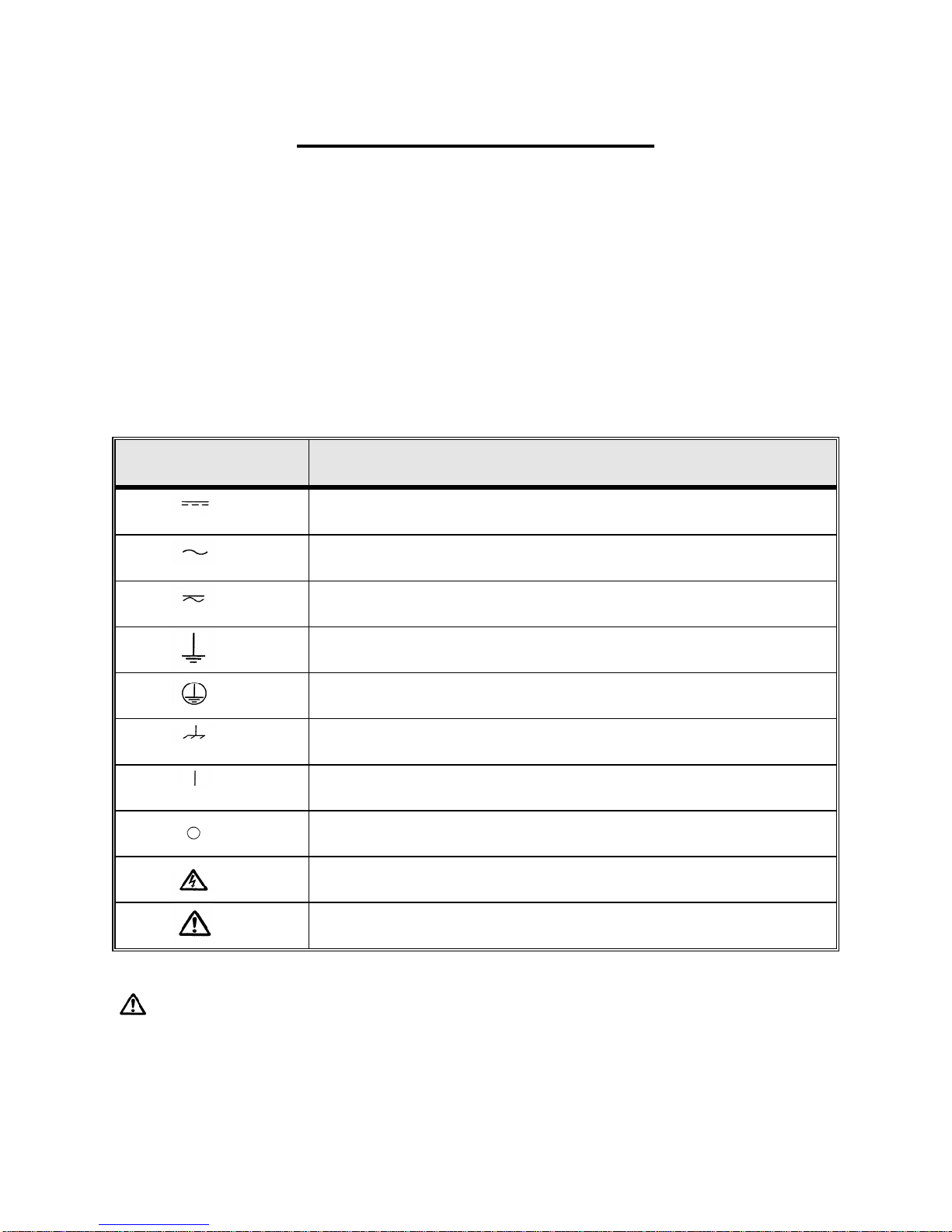
taken by the operator. Where applicable, IEC safety markings have been placed on the
instrument to notify the operator to refer to the user manual for instructions on correct use or
safety related topics. Refer to the following table of symbols and definitions.
Symbol
Description
Direct Current
Alternating Current
Both direct and alternating current
Earth (ground) Terminal. There is a common chassis ground terminal
located on the front panel (see Front panel under Description of Controls).
Protective Conductor Terminal
Frame or Chassis Terminal
On (Supply)
Off (Supply)
Caution, risk of electric shock
Caution (refer to accompanying documents)
WARNING: Under no circumstances should the operator or technician attempt to open or
service any Megger instrument while connected to a power source. Lethal voltages are present
and may cause serious injury or death!
Page 5

4 PN: 81127
Rev 4, 6/2017
SAFETY PRECAUTIONS (Continued)
The following are specific safety related items associated with the test system.
Read and understand all safety precautions and operation instructions before attempting
to use this unit.
The purpose of this equipment is limited to use as described in this instruction manual.
Should a situation arise that is not covered in the general or specific safety precaution
please contact Megger regional representative or Megger, Dallas, Texas.
Safety is the responsibility of the user. Misuse of this equipment can be extremely
dangerous.
Always start with the power OFF, before connecting the power cord. Make
sure outputs are off before attempting to make test connections.
Never connect the test set to energized equipment.
Always use properly insulated test leads. The optional test leads are rated for
the continuous output ratings of the test system, and should be properly used
and cared for. DO NOT use cracked or broken test leads.
Always turn the test system off before disconnecting the power cord.
DO NOT attempt to use the unit without a safety ground connected.
DO NOT attempt to use the unit if the power cord ground prong is broken or
missing.
DO NOT use the test set in an explosive or flammable atmosphere.
DO NOT use the test set in a wet environment.
The instrument must only be used by suitably trained and competent persons.
Observe all safety warnings marked on the equipment.
Safety related or other important topics, like the statement below, will be
notated with the adjoined symbol. Read the topic carefully as it may relate
either to the safe operation of the test system or the safety of the operator.
The Model SPI is not designed for use on energized circuits. For the safety of the
operator and protection of the instrument, do not connect it to circuits that are
energized. This includes circuits that could become energized during the
course of a test procedure utilizing this instrument.
Page 6

5 PN: 81127
Rev 4, 6/2017
Table of Contents
Section Page
STVI .............................................................................................................................................................. 0
Smart Touch View Interface ....................................................................................................................... 0
SPI225 ........................................................................................................................................................... 0
Smart Primary Injection Test System ....................................................................................................... 0
Revision History .......................................................................................................................................... 1
Safety Precautions ...................................................................................................................................... 3
1.0 STVI Introduction ............................................................................................................................. 8
1.1 Smart Touch View Interface ............................................................................................................... 8
1.2 Terminology ...................................................................................................................................... 9
1.2.1 Glossary of Terms for Circuit Breaker Testing ............................................................................... 9
1.2.2.1 Pickup (Tap / Sensitivity Rating) ................................................................................................. 9
1.2.2.2 Time Delay .................................................................................................................................. 9
1.2.2.2.1 Long-Time Delay ......................................................................................................................... 9
1.2.2.2.2 Short-Time Delay ........................................................................................................................ 9
1.2.2.3 Instantaneous.............................................................................................................................. 9
1.2.2.4 Test Multiple .............................................................................................................................. 10
1.2.2.5 Frame Size ................................................................................................................................ 10
1.2.2.6 Continuous Current Rating ....................................................................................................... 10
1.2.2.7 Expected Trip Time ................................................................................................................... 10
1.2.2.8 Interrupting Rating .................................................................................................................... 10
1.3 Power Over Ethernet Input Power ................................................................................................ 10
2.0 SETUP ............................................................................................................................................. 10
2.1 Unpack System ................................................................................................................................ 10
2.1.1 Initial Start Up ............................................................................................................................... 10
2.2 Communication Ports .................................................................................................................... 10
2.2.1 Ethernet Port ................................................................................................................................. 11
2.2.2 USB 2.0 Interface ......................................................................................................................... 11
2.3 Smart Touch View Interface .......................................................................................................... 12
2.3.1 Configuration ................................................................................................................................ 14
2.3.1.1 Max Time .................................................................................................................................. 15
2.3.1.2 Max Current .............................................................................................................................. 15
2.3.1.3 Tap Verification Current ............................................................................................................ 15
2.3.1.4 Timer Stop Cfg .......................................................................................................................... 15
2.3.1.4.1 Current Actuate Mode ............................................................................................................... 16
2.3.1.4.2 Normally Closed Contact Opening............................................................................................ 16
2.3.1.4.3 Normally Open Contact Closing ................................................................................................ 16
2.3.1.4.4 Voltage Applied ......................................................................................................................... 16
2.3.1.4.5 Voltage Removed...................................................................................................................... 16
2.3.1.4.6 Post Deb (Debounce) ............................................................................................................... 16
2.3.1.4.7 Post Volt Thres. (Voltage Threshold) ........................................................................................ 16
2.3.1.5 Help Button ............................................................................................................................... 17
2.3.1.6 Default Settings Options ........................................................................................................... 17
2.3.1.6.1 Save as Default ......................................................................................................................... 17
2.3.1.6.2 Restore Default ......................................................................................................................... 17
2.3.1.6.3 Restore Factory......................................................................................................................... 17
2.3.1.7 Versions (Information Screen) .................................................................................................. 17
2.3.1.8 Update Firmware....................................................................................................................... 17
2.3.1.9 Current Status ........................................................................................................................... 17
2.3.1.10 Time Unit ................................................................................................................................... 17
2.3.1.11 Bluetooth Pwd ........................................................................................................................... 18
2.3.1.12 Line Freq ................................................................................................................................... 18
Page 7

6 PN: 81127
Rev 4, 6/2017
2.3.1.13 Ld (Load) Connection ............................................................................................................... 18
2.3.1.14 Color Options ............................................................................................................................ 18
2.3.1.15 Pickup Ramp Rate .................................................................................................................... 18
2.3.1.16 Pulse On Duration ..................................................................................................................... 18
2.3.1.17 Pulse Off Duration ..................................................................................................................... 18
2.3.1.18 Ethernet (DHCP) IP Address .................................................................................................... 18
2.3.1.19 Set Date and Time .................................................................................................................... 19
2.3.1.20 Number Format ......................................................................................................................... 19
2.3.1.21 Adjust Screen Brightness .......................................................................................................... 19
2.3.1.22 Logging ..................................................................................................................................... 19
2.3.1.23 Screen Exit ................................................................................................................................ 19
2.4 Setting Output Currents ................................................................................................................ 20
2.4.1 Numeric Keypad Entry .................................................................................................................. 20
2.4.2 Manual Ramping ........................................................................................................................... 20
2.4.3 Control Knob ................................................................................................................................. 21
2.4.4 Virtual Alphanumeric Keypad ....................................................................................................... 21
2.5 STVI - File Management ................................................................................................................. 22
3.0 STVI – Basic Operating Descriptions ........................................................................................... 24
3.1 STVI / PC Manual Test Screen ...................................................................................................... 24
3.1.1 Home button ................................................................................................................................. 24
3.1.2 Configuration button ..................................................................................................................... 24
3.1.3 Add To Report button ................................................................................................................... 25
3.1.4 Clear Results button ..................................................................................................................... 25
3.1.5 Nameplate Data button ................................................................................................................. 25
3.1.6 System Reset button .................................................................................................................... 25
3.1.7 System Reset button .................................................................................................................... 25
3.1.8 System Reset button .................................................................................................................... 25
3.1.9 System Reset button .................................................................................................................... 25
3.1.10 Requested Current (A) Amplitude Button ..................................................................................... 25
3.1.11 Mode button .................................................................................................................................. 25
3.1.11.1 Momentary Mode ...................................................................................................................... 26
3.1.11.2 Continuous Mode ...................................................................................................................... 26
3.1.12 Mode button .................................................................................................................................. 26
3.1.13 Play button .................................................................................................................................... 26
3.1.14 Timer Display Window .............................................................................................................. 28
3.1.15 Output Current Amplitude Window ........................................................................................... 28
3.2 Selection of SPI225 Output Terminals ......................................................................................... 28
3.2.1 Selection of Output Leads ............................................................................................................ 28
3.3 SPI225 Output Current and Overload Capability ........................................................................ 30
3.3.1 Parallel Operation ......................................................................................................................... 31
3.3.1.1 Two SPI Units in Parallel .......................................................................................................... 31
3.3.1.2 Three or Four SPI Units in Parallel ........................................................................................... 32
3.3.2 Series Operation ........................................................................................................................... 33
3.4 Manual Test ..................................................................................................................................... 35
3.4.1 Timing Test ................................................................................................................................... 35
3.4.2 Testing Instantaneous Pickup ...................................................................................................... 37
3.5 Advanced Pickup and Timing Test ............................................................................................... 39
3.5.1 Advanced Timing Test Setup ....................................................................................................... 39
3.5.1.1 Breaker Manufacturer and Curve Selection .............................................................................. 40
3.5.2 Advanced Pickup and Timing Test Screen .................................................................................. 41
3.5.2.1 PC or STVI to SPI connection button ....................................................................................... 41
3.5.2.2 Configuration button .................................................................................................................. 41
3.5.2.3 View Report button ................................................................................................................... 41
3.5.2.4 Clear Results button ................................................................................................................. 42
3.5.2.5 Nameplate Data button ............................................................................................................. 42
3.5.2.6 Home button .............................................................................................................................. 42
Page 8

7 PN: 81127
Rev 4, 6/2017
3.5.2.7 System Reset button ................................................................................................................. 42
3.5.2.8 File Folder button ...................................................................................................................... 42
3.5.2.9 Long Time Delay Test Selection button .................................................................................... 42
3.5.2.10 Short Time Delay Test Selection button ................................................................................... 42
3.5.2.11 Instantaneous Test Selection button ........................................................................................ 42
3.5.2.12 Ground Trip Test Selection button ............................................................................................ 42
3.5.2.13 Time Curve Test Display ........................................................................................................... 42
3.5.2.14 Select Breaker Curve button ..................................................................................................... 43
3.5.2.15 Frame Size, Sensitivity Rating, Band and Pickup windows ...................................................... 43
3.5.2.16 Pickup and Timing Test Selection windows .............................................................................. 43
3.5.2.16.1 Automated Pickup Tests ....................................................................................................... 43
3.5.2.16.2 Automated Timing Tests ....................................................................................................... 43
3.5.2.17 Help button ................................................................................................................................ 43
3.5.3 Advanced Automated (Manufacturer Specific) Timing Test ......................................................... 44
3.5.4 Advanced Manual (Generic) Timing Test ..................................................................................... 46
4.0 Warranty Statement ....................................................................................................................... 48
5.0 Service Data .................................................................................................................................... 48
5.1 Preventive Maintenance ................................................................................................................ 48
5.1.1 Examine the Unit .......................................................................................................................... 48
5.1.2 Upgrading STVI Software ............................................................................................................. 48
5.2 Updating SPI225 Firmware ............................................................................................................ 49
5.3 Service and Repair Instructions ................................................................................................... 50
5.3.1 Basic Troubleshooting .................................................................................................................. 50
5.3.1.1 Power Input ............................................................................................................................... 50
5.3.1.2 Ethernet Cable .......................................................................................................................... 51
6.0 Preparation for Reshipment .......................................................................................................... 51
Page 9
8 PN: 81127
Rev 4, 6/2017
1.0 STVI Introduction
The STVI is a user friendly interface to control the Megger SPI test equipment. This manual contains the
information that you will need in order to set up and use your STVI with the SPI Device. How the unit
operates, some of the different types of testing you can do, and how to save and view your test results
with the Smart Touch View Interface software is described. It also covers running the STVI software
using the PowerDB software on your PC.
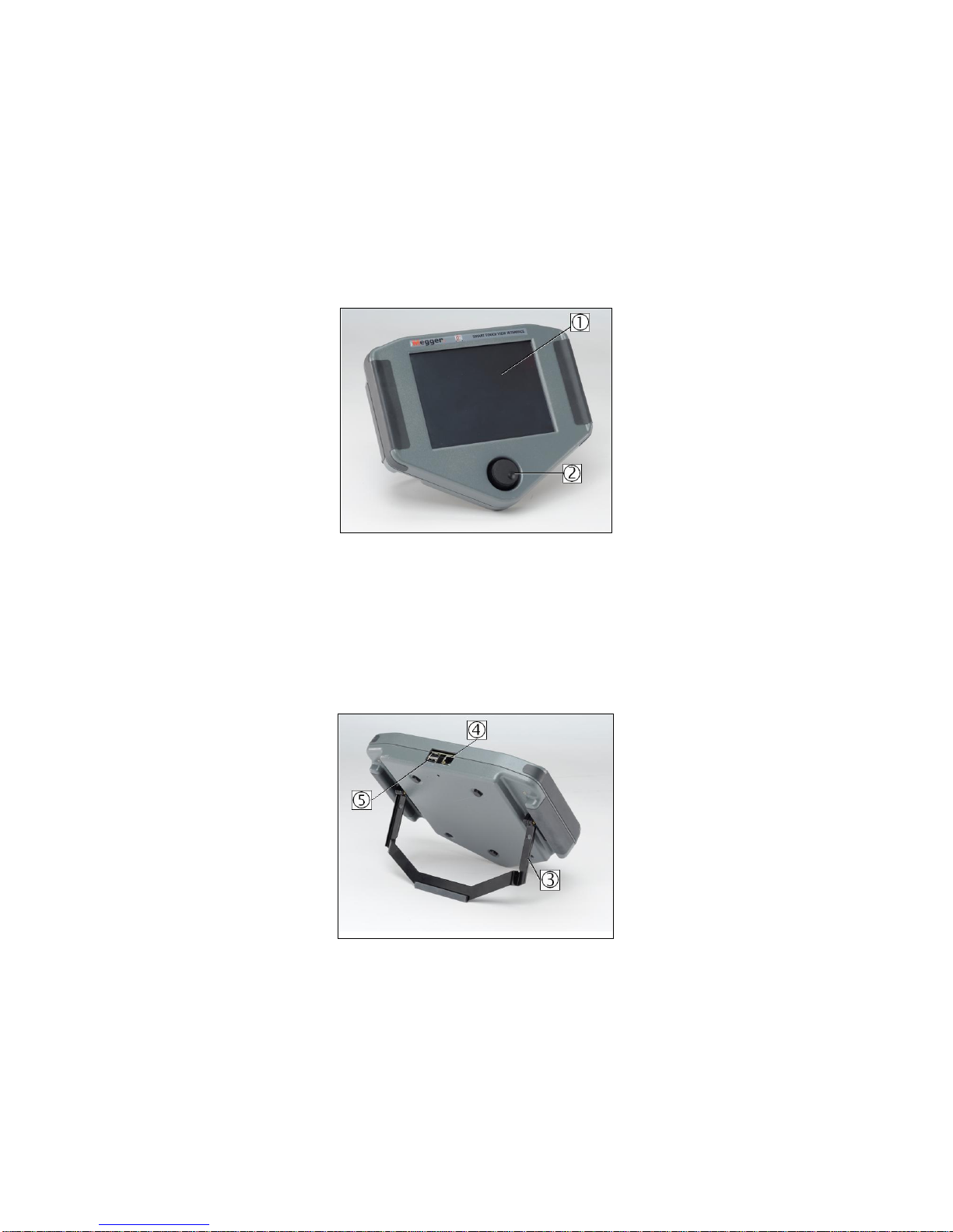
1.1 Smart Touch View Interface
Figure 1 - Smart Touch View Interface
1. TFT LCD Color Display – this 8.5 inch touch panel display provides high resolution, and features
Wide Viewing Angle Technology with high luminance for reading in direct sunlight.
2. Control Knob – this knob will adjust values once the box location of the value to be changed is
selected.
Figure 2 - STVI Rear-View
3. Built-in Foldout Stand – the STVI may be operated as a handheld controller, or foldout the
built-in stand and use a desktop controller.
4. STVI Ethernet Port – this Ethernet port is a 10/100BaseTX PoE (Power over Ethernet) port, and
is the SPI connection port.
Page 10

9 PN: 81127
Rev 4, 6/2017
5. USB Interface – the USB port is used to update the firmware in the SPI as well as update the
software in the STVI using a USB memory stick. It may also be used to download test results
from the STVI for download into another PC with Power DB software for storage or printing. For
control of the SPI, an Ethernet cable is provided. The STVI gets its power over the Ethernet
cable. Even though the STVI has a built-in virtual keyboard, the user can use a USB keyboard
with the STVI, as well as a mouse (including Logitech wireless mouse). The keyboard and/or
mouse are not provided with the accessories.
1.2 Terminology
The acronyms, terms, and definitions used throughout this manual are described below:
1.2.1 Glossary of Terms for Circuit Breaker Testing
The STVI display screens prompt the user to select, or set, various values. The values vary depending
on the protective device under test. Many of the terms used are similar in nature and mean virtually the
same thing regardless of the type of breaker. For example, the term Time Dial is commonly used to
define the time dial setting on the device under test. Unfortunately, some of the terms described here
may apply to different types of devices under test in different ways, and thus may not cover every
possible device made. However, it is hoped that this glossary will help the user to understand every
setting value on every device under test.
1.2.2.1 Pickup (Tap / Sensitivity Rating)
A numerical value associated with a tap or sensitivity rating setting on the device under test. It is used to
define a setting value, pick up value, or minimum operating point, of the device under test.
1.2.2.2 Time Delay
It is a numerical value of time, normally associated with the minimum operating time of the device under
test. Low Voltage Power Circuit Breakers are available with three types of tripping characteristics: LongTime, Short-Time, and Instantaneous.
1.2.2.2.1 Long-Time Delay
The long time delay characteristic is normally associated with direct acting low voltage power circuit
breakers providing overload protection with typical time delays of approximately 10 - 60 seconds at 300%
of pickup.
1.2.2.2.2 Short-Time Delay
The short time delay characteristic is normally associated with direct acting low voltage power circuit
breakers providing protection for short circuit or fault conditions. It is used whenever a small delay is
necessary for coordination or selectivity with other protective devices. Typical delays of this type
characteristic are approximately 6-30 cycles.
1.2.2.3 Instantaneous
A numerical value associated with a tap setting of the instantaneous element of the device under test. It
is used to define a pick up value, or minimum operating point, of the instantaneous element of the device
under test. The instantaneous trip characteristic is used for short circuit or fault protection and has no
intentional time delay.
Page 11

10 PN: 81127
Rev 4, 6/2017
1.2.2.4 Test Multiple
A numerical value normally associated with timing tests. Multiples are normally expressed in terms of
whole numbers like 2, 3, 4, etc., times the Pickup or Tap value of the device under test. Fractions of test
multiples may also be entered and the appropriate test values and theoretical trip times will be calculated
automatically.
1.2.2.5 Frame Size
The frame rating is the maximum continuous current rating in amperes of all parts except the overcurrent
device. All current-carrying parts, contacts, and pivot points are designed to carry current up to the frame
size rating without exceeding heating limits.
1.2.2.6 Continuous Current Rating
The continuous current rating is a current value equal to or less than the frame rating. This value of
current is printed or stamped on the overcurrent device. It is possible to have a 600-ampere frame rating,
with a continuous current rating of only 100 amperes (due to the size of the overcurrent trip device).
1.2.2.7 Expected Trip Time
A numerical value representing the expected operating time of the device under test.
1.2.2.8 Interrupting Rating
A numerical value associated with the highest current at rated voltage that the device can interrupt
without external damage.
1.3 Power Over Ethernet Input Power
The STVI gets Power Over Ethernet (PoE) of 48 Volts DC at 0.5 A from the SPI STVI port.
2.0 SETUP
2.1 Unpack System
Unpack the unit and check for evidence of any shipping damage. If there is any visual damage,
immediately notify the freight carrier to make a damage claim, and notify Megger of the damage.
2.1.1 Initial Start Up
1. With the Ethernet cable supplied with the unit, connect the STVI Ethernet Port on the SPI unit to
the Ethernet port on the top of the Smart Touch View Interface (STVI).
2. Before connecting power to the unit, make sure the SPI POWER ON/OFF Switch is in the OFF
position (0). Plug the unit line cord into an appropriate power source and turn the POWER
ON/OFF Switch to ON (1). As the SPI unit goes through its power up sequence, in about a
minute the STVI power up screen will appear, then the manual start up screen will appear.
2.2 Communication Ports
There are two types of communication ports on the STVI, one Ethernet, and two USB ports. On the SPI
unit there is a USB port and three Ethernet ports.
Page 12

11 PN: 81127
Rev 4, 6/2017
2.2.1 Ethernet Port
There is one Ethernet port on the STVI for connecting to the SPI unit. Connect the STVI to the SPI unit
using the port labeled STVI (as shown in Figure 3).
Figure 3 - STVI port on the SPI
2.2.2 USB 2.0 Interface
There are two USB 2.0 Interface ports on the STVI unit (see Figure 2). These ports are used for
upgrading firmware in the unit, or upgrading the STVI software using a USB Memory Stick. They may
also be used in conjunction with a USB mouse for ease of manual control, even a USB wireless mouse
may be used with the STVI.
The Ethernet Port labeled “IN” is a 10/100BaseTX port, and is the primary PC connection port. This port
supports MDI/MDI-X auto crossover configuration, which means both standard and “crossover” Ethernet
cables may be used. Note that only one of the Ethernet ports may be used at a time (the intended use is
for control by the STVI or the PC).
Page 13
12 PN: 81127
Rev 4, 6/2017
2.3 Smart Touch View Interface
The STVI is the manual control and user interface for the unit. All manual entries will be made through
the STVI unless the unit is connected to a personal computer. During the power up sequence the test
system automatically does a self-test to insure everything is operating properly. Once the system has
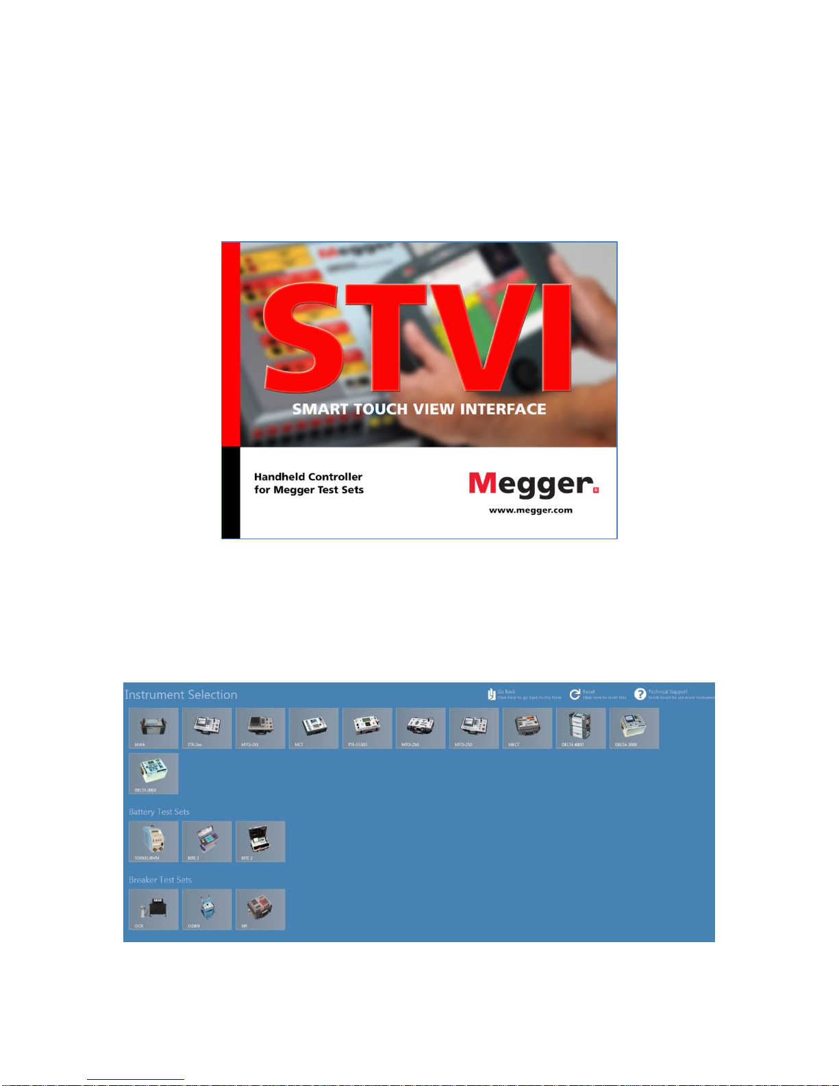
completed it’s self-checks the Introduction Screen will appear as shown in Figure 4. If the software
detects a SPI it will be automatically connected and the main SPI Startup Screen (Figure 8) will be
displayed.
Figure 4 - Introduction Screen
When using the PC version of the STVI software, the Instrument Selection Screen will be displayed.
Note that the software is used to communicate with numerous instruments. The SPI icon should be
located under the heading of Breaker Test Sets. Click on the SPI button in the Instrument Selection
Screen to connect to a SPI.
Figure 5 - Instrument Selection Screen
Page 14
13 PN: 81127
Rev 4, 6/2017
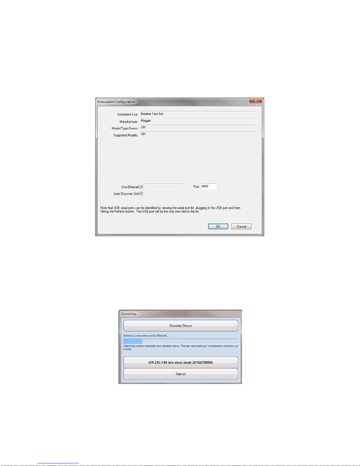
The PC version will then display the Instrument Configuration screen as shown in Figure 6. Click the OK
button and the software will attempt to auto detect an instrument and connect. If no instrument is
detected due to firewall, VPN settings or an incorrect IP address the user will need to take appropriate
corrective action. In this case the firewall can be turned off or you can enter the IP address directly using
the Instrument Configuration screen. The user can un-check the Auto Discover Unit box and enter the IP
address directly in the field provided. The Auto Config IP address of the SPI unit can be found on the
nameplate of the test set.
Figure 6 - Instrument Configuration Screen
If the unit is on a network with a DHCP server, the user must use the Auto Discovery mode. Note that the
SPI Port selection field should be set to port 8000.
If the software detects a unit, the user will be shown a connection dialog similar to Figure 7. The user can
then select the desired SPI unit for connection.
Figure 7 – Connection Dialog
Page 15
14 PN: 81127
Rev 4, 6/2017
The PC version of the software will then display the main SPI Startup Screen. Note that the connection
icon in the upper left corner will have a green background indicating that the SPI unit is connected
and the IP address was automatically set through the Ethernet port. The auto-detect process does not
require the user to enter an IP address. Once the software detects and connects to a unit, the connection
icon background will turn green and the SPI Startup Screen will appear (as shown in Figure 8).
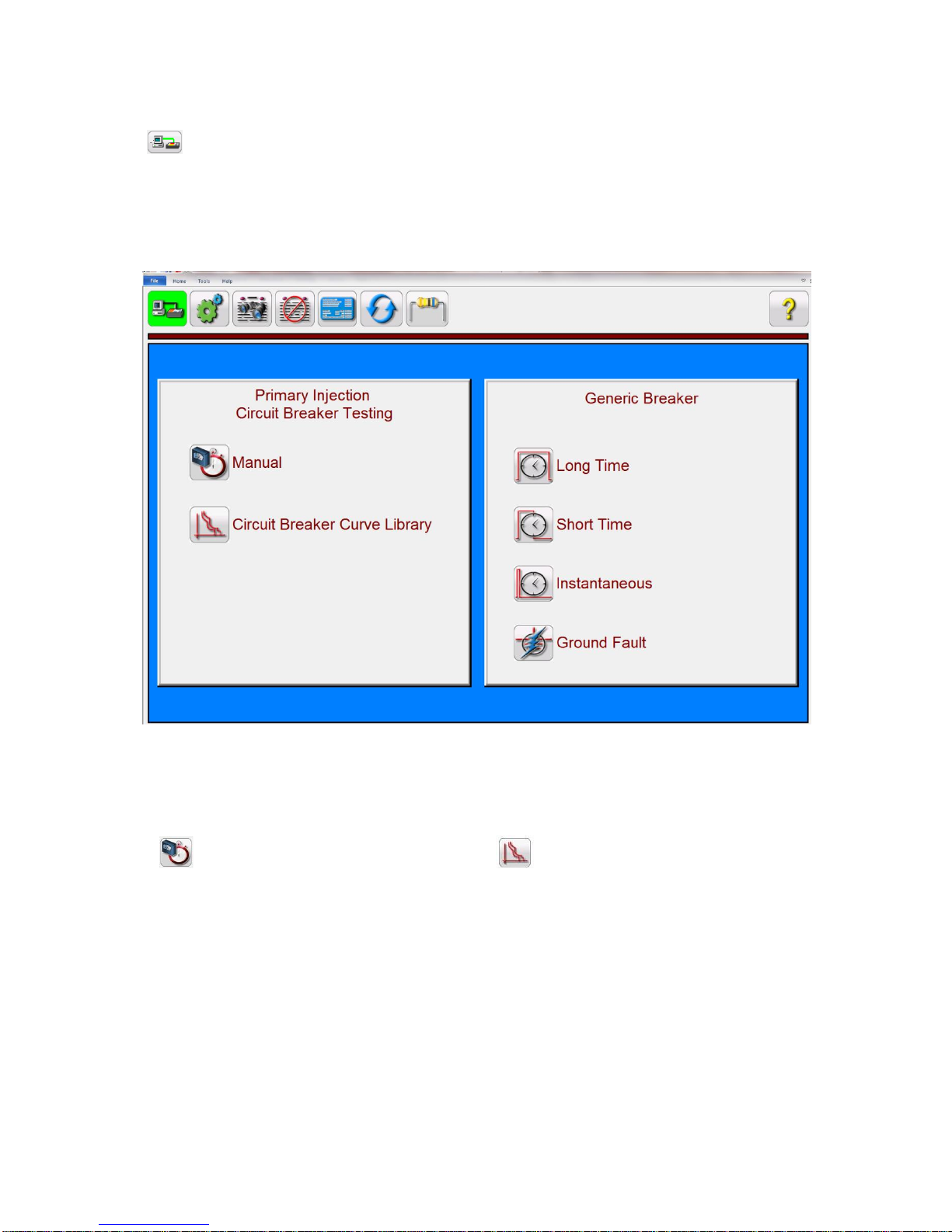
Figure 8 - SPI Startup Screen
The SPI Startup screen provides access to the Manual test screen by pressing the Manual test
button , or the Circuit Breaker Curve Library button . The Circuit Breaker Curve Library screen
provides automated timing tests of circuit breakers and overload devices using either Generic or
Manufacturer Specific time curves. The software has ANSI and IEC standard time curve algorithms builtin for molded case breakers. In addition, it includes time curves and time curve algorithms for different
specific molded case and air frame circuit breakers selectable by Manufacturer, Breaker Type, Curve
Family, Curve Model, Curve Trip Unit and Curve Name as applicable.
If this is the first time you have started up the SPI software it is recommended that you go to the
Configuration Screen first to setup the hardware, maximum durations, test currents, pulse times, and the
timer configuration.
2.3.1 Configuration
Page 16
15 PN: 81127
Rev 4, 6/2017
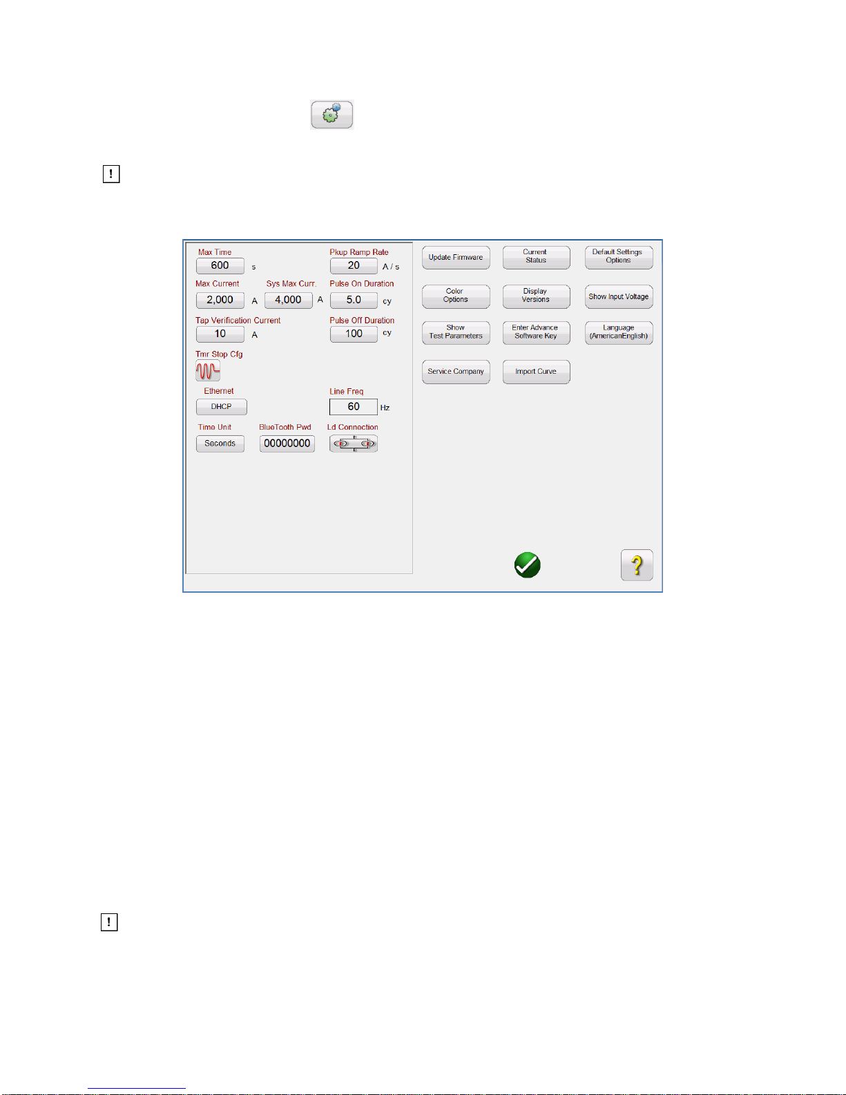
Pressing the Configuration button will allow the user to configure both the SPI hardware and SPI
software. Pressing this button will display the Configuration screen (see Figure 9).
Note: The following button descriptions vary depending on hardware configuration and the
version of the SPI software. The STVI version of the software includes extra buttons as indicated
with an * in the descriptions below.
Figure 9 – SPI Configuration Screen
2.3.1.1 Max Time
The user can set the Maximum Time in seconds that the SPI will stay ON during a test. The default value
is 600 seconds.
2.3.1.2 Max Current
The user can set the Maximum Current that the SPI will output on the selected Output Tap. The default
value is 2000 Amps.
2.3.1.3 Tap Verification Current
This is a time saving feature used to automatically determine the Output Tap selected by the user. The
user simply connects to the desired output tap, and then to the device under test. Prior to applying a test
current the unit will pulse the Tap Verification Current into the load. Based upon the current value read
back by the measuring circuit, and knowing the ratio of the output taps, the software will automatically
reconfigure for the selected output tap. The default is 10 Amps.
Make sure that the Tap Verification Current value is below any instantaneous setting or
ground trip device setting of the device under test.
2.3.1.4 Timer Stop Cfg
Page 17

16 PN: 81127
Rev 4, 6/2017
Controls the modes to stop the Timer and turn the output off. Pressing the button will present to the user
with three selections: Current Actuate, Dry Contacts Normally Open/Closed, and Voltage
Applied/Removed, see the following descriptions.
2.3.1.4.1 Current Actuate Mode
Current Actuate Mode: Timer will initiate only when the output circuit is completed, and a threshold
current of approximately 10% of the selected test current is exceeded. Timer will continue to run until
output circuit opens and the current drops below threshold level or output is de-energized by the user.
2.3.1.4.2 Normally Closed Contact Opening
With the BINARY INPUT terminals connected to normally closed external contacts, output circuit will
remain energized and timer will continue to run until contacts open.
2.3.1.4.3 Normally Open Contact Closing
With the BINARY INPUT terminals connected to normally open external contacts, output circuit will
remain energized and timer will continue to run until contacts close.
2.3.1.4.4 Voltage Applied
With the BINARY INPUT terminals connected to an external monitoring circuit, output circuit will
remain energized and timer will continue to run until an AC or DC Voltage is applied.
2.3.1.4.5 Voltage Removed
With the BINARY INPUT terminals connected to an external monitoring circuit, output circuit will
remain energized and timer will continue to run until an AC or DC Voltage is removed.
2.3.1.4.6 Post Deb (Debounce time)
This setting is associated with the BINARY INPUT Terminals, and Normally Open Contacts closing.
The Debounce time is set in milliseconds. The trip contacts must stay closed for the duration of the
Debounce time setting for the time test to be true. If the contacts open in less than the set Debounce
time the timer will continue to run. Once the input condition is true then the time test will conclude.
The trip time displayed will be the total test time less the debounce time.
2.3.1.4.7 Post Volt Thres. (Voltage Threshold)
This setting is associated with the BINARY INPUT Terminals and Voltage Applied test applications.
To serve a wide range of test applications the BINARY INPUT has a programmable voltage
threshold. For typical test applications the binary input has a defaulted threshold of 5 volts. A higher
threshold voltage helps to eliminate false triggers due to a noisy source. Lower thresholds allow
stopping of timer from TTL voltage signals. The allowable voltage applied is 1 to 300 Volts AC or DC,
programmable in 1 Volt increments.
Page 18

17 PN: 81127
Rev 4, 6/2017
2.3.1.5 Help Button
Press this button to access the built-in manual or for help associated with the Configuration Screen.
2.3.1.6 Default Settings Options
Press this button to get access to the settings options of Save as Default, Restore Default, and Restore
Factory default settings (see Figure 10).
Figure 10 - Default Settings Options
2.3.1.6.1 Save as Default
Press this button and all of the changes made to the Configuration Screen and most of the
default values for all screens are now saved as the power up defaults.
2.3.1.6.2 Restore Default
Pressing this button provides the ability to restore the original system power up defaults.
2.3.1.6.3 Restore Factory
Pressing this button provides the ability to restore the original system factory power up defaults.
2.3.1.7 Display Versions (Information Screen)
Pressing this button will display model, serial number, software and firmware versions, and build dates.
This information is useful when calling Megger for service or technical support related issues.
2.3.1.8 Update Firmware
This button is used to update the SPI firmware.
2.3.1.9 Current Status
Displays the SPI current status screen. This information is mainly for use by Megger support staff.
2.3.1.10 Time Unit
Page 19

18 PN: 81127
Rev 4, 6/2017
Set the time unit display to seconds or cycles.
2.3.1.11 Bluetooth Pwd
This button allows the user to set the SPI Bluetooth password.
2.3.1.12 Line Freq
This button displays the current Line Frequency.
2.3.1.13 Ld (Load) Connection
This button appears when the user selects one or more Slave units. This button provides for either
Parallel or Series connections of multiple SPI units. Press or click on the Ld
Connection button to toggle between Series or Parallel. In the parallel mode the SPI software will
automatically divide the requested test current by the number of units and output equally the same test
current from each unit in parallel so that the currents add across the load to equal the requested current
value. If two units are in series, it will set the requested test current from each unit so that the compliance
voltage from each unit will add together to push the current through the load.
2.3.1.14 Color Options
Press this button to adjust the colors of the vectors, backgrounds, lettering, etc.
2.3.1.15 Pickup Ramp Rate
Press this button to set the Current Ramp Rate in Amps/Sec to be used in the Pickup Test in the
Advanced Screen.
2.3.1.16 Pulse On Duration
Press this button to set the Pulse ON time in Cycles. Used when operating the test set in the Momentary
mode in the manual test screen, or when performing Instantaneous Pickup tests in the Automatic Mode.
2.3.1.17 Pulse Off Duration
Press this button to set the Pulse OFF time used in pulse ramping.
2.3.1.18 Ethernet (DHCP) IP Address
The STVI will auto-detect the SPI unit (the DHCP mode does not require the user to input an IP address).
If the unit is on a network with a DHCP server, the user must use the Auto Discovery mode. Using the
STVI, pressing the DHCP button will produce the Static IP Address Dialog box.
Figure 11 - Static IP Address Dialog Box
If using the PC version it too can auto-discover the SPI unit connected to the PC. On the PC version, the
PC might not auto detect due to firewall, VPN settings or anti-virus software. In this case the firewall can
be turned off, or you can enter the IP address directly using the PowerDB Instrument Configuration
Page 20

19 PN: 81127
Rev 4, 6/2017
screen by clicking the SPI icon on the Instrument Selection screen (Figure 12). Un-checking the Auto
Discover Unit box will enable the IP address entry box (shown highlighted in red in Figure 12).
The AutoConfig IP address of the SPI225 unit can be found on the nameplate of the unit.
Figure 12 - PowerDB Instrument Configuration Screen
2.3.1.19 Set Date and Time*
Press this button to set the Date and Time in the STVI. This information is critical for saving tests and test
results using the internal file manager. The PC version uses the PC time and date.
2.3.1.20 Number Format*
Press this button to set the decimal point number format either as a period or as a comma.
2.3.1.21 Adjust Screen Brightness*
The brightness is adjustable on the STVI. The display will always be visible since hardware limits the
brightness from becoming too bright or too dark to be seen. Press this button and use the Control Knob
to increase or decrease the brightness. For the PC version use the PC screen controls to adjust the
display.
2.3.1.22 Logging*
Select this button to set up the logging with the STVI. The log will store a record of the commands sent to
the SPI unit from the STVI (used when troubleshooting).
2.3.1.23 Screen Exit
Page 21

20 PN: 81127
Rev 4, 6/2017
To exit the screen and return to the previous screen press the green check button (you will see this
same button on other screens).
2.4 Setting Output Currents
Pressing the Requested Current button on the STVI hand held controller will display the following pop-up
numeric keypad to enter the required test current. If using the PC version, click in the Requested Current
window and use the PC keyboard numeric keys to enter the desired output current value.
2.4.1 Numeric Keypad Entry
The STVI numeric keypad entry provides an interface to the user when entering values using the STVI
touch screen. Touching a data entry window (Requested Current or Increment) on the STVI will activate
the Numeric Keypad. If using the PC version of the software, click in the window using the mouse. Use
the numeric keys to type in the value you want and press the button (press the Enter key on the PC).
Pressing the clear all will clear the value you just entered. Pressing the clear last digit button
will clear the least significant digit of the value in the display window.
Figure 13 - STVI Numeric Keypad
The button will enter the value and take you back to the test screen. Pressing Cancel will return
the user to the previous screen that is in use.
2.4.2 Manual Ramping
The output current can be ramped manually using either the Control Knob on the STVI or the up/down
arrow keys/mouse wheel on the PC version. The amplitude of each step is set using the Increment
Selection Screen (Figure 14) accessed by pressing the Increment button.
Page 22

21 PN: 81127
Rev 4, 6/2017
Figure 14 - Increment Selection Screen
Increment – Select the desired increment. The value selected will be shown on the Increment button.
The output current will increment in 1, 5, 10, 15, or 20 Amp increments. The Auto button is associated
with the control knob on the STVI, see Control Knob for more information.
In the Momentary Mode (see section 3.1.11.1) the output current will come on after pressing the blue Play
button, and will only stay on for the Pulse On Duration Time setting in the Configuration Screen (see
2.3.1.15). When rotating the Control Knob, or the up/down cursor arrows on the PC keyboard, the output
current will pulse on for the Duration Time with each increment, thus allowing an instantaneous pickup
test (Duration Time needs to be set longer than the expected instantaneous pickup time).
In the Continuous Mode (see section 3.1.11.2) the output can be ramped using the control knob or the
up/down cursor arrows on the PC keyboard, and the output current will stay on until the device trips or
until the user presses either the Simulate Contact button or the Red X button that appear
at the top of the test screen.
2.4.3 Control Knob
The control knob will change the value of the output current based upon the increment value setting, after
the blue Play button is pressed. Clockwise rotation increases and counterclockwise decreases. In the
Auto Increment Mode the control knob uses a speed control algorithm to provide fine adjustment, with a
slow rotation (one click equals the lowest increment level), and a larger step adjustment with a faster
rotation. The Control Knob can also be used to scroll up and down when viewing the test results in the
Add Results and View Results screens, or when viewing the Help screen.
2.4.4 Virtual Alphanumeric Keyboard
The virtual alphanumeric keyboard allows the entry of ASCII text into the appropriate STVI windows. This
keypad is used to enter information in the Nameplate Data screen or file names in the file management
screen.
Page 23

22 PN: 81127
Rev 4, 6/2017
Figure 15 - STVI Virtual Alphanumeric Keyboard
2.5 STVI - File Management
The file management display is used by the STVI hand held controller to access files stored in the STVI’s
internal memory. This display will allow test files to be loaded, make/change directories, rename
files/directories and delete files/directories that were created by the user. To access the File
Management system, touch the File Folder icon at the top of the test screen. This icon only appears
on the STVI (not on PC version). It provides the user the ability to save tests or open saved tests. If using
the PC version users will have the PowerDB file system to save test (job) files (see PowerDB Help).
Pressing the File Folder icon presents the user with the following tool bar (Figure 16). It defaults to the
Save Current Form icon highlighted.
Figure 16 - STVI File Folder Tool Bar
Note: Pressing the Power ON/OFF button will power down the STVI but is not required for a safe
shutdown.
Pressing on the highlighted folder will provide the user with the following file explorer screen.
Figure 17 - STVI File Folder Explorer
Page 24

23 PN: 81127
Rev 4, 6/2017
Press in the File Name field and the user will be provided with the virtual keyboard to enter a file name.
The file can then be saved to the internal memory or saved to a USB memory stick. This same window is
also used to open saved files. To save results directly to a USB memory stick check the Save to USB
box. To transfer test results from the STVI to a USB memory stick use the up down blue colored buttons
to selected the desired test result to be transferred and then press on the USB button. To retrieve a
test file from a USB memory stick press on the USB button to retrieve the selected file from the list of
files that appear in the right hand window. To delete a file use the up/down arrows to highlight the file and
then press the trash can icon. The left pointing blue arrow is the exit button to go back to the
test screen. To open an existing test file from the File Folder tool bar, press the Open File Folder icon
. The user will be presented with the File Folder Explorer. Use the up/down blue arrows buttons to
highlight the desired file to be opened, and then press the Open File Folder button in the lower left corner.
The user will be presented with a menu bar to open a New Test or to open the file selected showing the
date and time of the saved file. Pressing the date/time button will open the saved test. To view the saved
results press the More button in the upper right display next to the vector screen, then press the
View Report button.
Page 25

24 PN: 81127
Rev 4, 6/2017
3.0 STVI – Basic Operating Descriptions
This section describes basic operating procedures for using the STVI with the SPI for such applications
as basic pickup, basic timing test, paralleling current outputs from multiple SPI units.
3.1 STVI / PC Manual Test Screen
Pressing the Manual test button will present the user with the Manual Test screen.
Figure 18 - Manual Test Screen
Note: the Current and Time windows do not appear until the test is started by pushing the blue play
button.
3.1.1 Home button
The HOME button is used in several screens. Pressing the Home button takes the user back to the Start
Up Screen.
3.1.2 Configuration Button
Press the button to go to the STVI Configuration Screen. See Section 2.3.1 Configuration for more
information of the Configuration Screen.
Page 26

25 PN: 81127
Rev 4, 6/2017
3.1.3 Add To Report Button
Press this button to either View Report or Add to the Report. It also allows the user to enter limits,
comments or deficiencies. Reports can be saved to the STVI internal memory and transferred to
PowerDB via a USB memory stick. Previous tests results can be loaded and the ‘Retest’ option can be
used to repeat the test using the same parameters as the previous test.
3.1.4 Clear Results Button
Press or click on the Clear Results button to Clear Active (last test) or Clear All test results that have been
added to the report.
3.1.5 Nameplate Data Button
Press this button to go to the Nameplate Data entry screen. Here the user can input all the related data
associated with the device under test. This information will appear in the Test Result Header.
3.1.6 System Reset Button
The SPI unit is self protected against internal overcurrent in the amplifier, and thermal overloads. In the
event that the unit should alarm off due to one of these situations the system must be reset before testing
can continue. Press the System Reset button to reset the error sensing circuitry.
3.1.7 Insulation/Contact Resistance Button
Allows the user to enter insulation and contact resistance data for the device under test. This data is not
determined by the SPI test set.
3.1.8 File Folder
It provides the user the ability to save tests and test results, or open saved tests or test results (see
section 2.5). If using the PC version users will have the PowerDB file system to save test (job) files (see
PowerDB Help).
3.1.9 Help Button
Press this button to access the online manual or for help associated with the Configuration Screen.
3.1.10 Requested Current (A) Amplitude Button
Pressing or clicking this button will provide the user with the virtual numeric keypad (STVI), or use the
keyboard (PC version) to enter the desired test current.
3.1.11 11 Mode Button
Pressing or clicking on the Mode button will toggle between Continuous and Momentary Modes.
Page 27

26 PN: 81127
Rev 4, 6/2017
3.1.11.1 Momentary Mode
In the Momentary Mode the output current will come on after pressing the Blue Play button, and will only
stay on for the Pulse On Duration Time setting in the Configuration Screen, see 2.3.1.14. When rotating
the Control Knob, or the up/down cursor arrows on the PC keyboard, the output current will pulse on for
the Duration Time with each increment, thus allowing an instantaneous pickup test (Duration Time needs
to be set longer than the expected instantaneous pickup time).
3.1.11.2 Continuous Mode
In the Continuous Mode the output will stay on until the device trips, or until the user presses either the
Simulate Contact button or the Red X button that appear at the top of the test screen.
The output can be ramped using the control knob or the up/down cursor arrows on the PC keyboard.
3.1.12 12 Increment Window
Pressing or clicking this window will provide the user with the Increment selection screen to enter the
desired increment current level to be used when doing pickup tests (either manually or in the automatic
modes). See 2.4.2 for more information.
3.1.13 13 Play button
Pressing or clicking the blue play button will start the test. If in the Momentary Mode the following
parameters screen will be displayed for the user to enter the test values and setup the timer stop
configuration.
Figure 19 - Momentary Mode Pulse Test Parameters Screen
The Output Current previously set in the test screen will be displayed. The Max Time and Max Current
settings from the Configuration screen are displayed. Touch or click in the appropriate window to change
the defaulted values. Stop Post Configuration allows the user to set the desired mode to stop the timer
and turn the outputs off, see section 2.3.1.3. Press the Increment button to display the Increment values
selection window. Select the size of the desired increment Ramp Rate in Amps / Pulse. Press the green
Page 28

27 PN: 81127
Rev 4, 6/2017
check button to return to the test screen and start the test. Note that if there are two or more units
connected in parallel (see the Parallel | Series button in the test parameters screen) the Pretest current
will be equally divided between the multiple units. If in series the Pretest current will be equal to the
Pretest Current value setting.
Make sure that the Pretest Current value is below any instantaneous setting, or ground trip device
setting of the device under test.
In the manual test screen, in the Momentary Mode, each time the Control Knob (or the PC cursor arrows)
are moved the output will turn on for the Pulse On Time value entered, and will increment the value
entered in the Ramp Inc window (up or down). The test is automatically stopped when the Timer Stop
condition is true. To manually stop the test or turn the output off, press or click on the red button, or
press the Simulate Contact button.
If the Continuous Mode is selected the following parameters screen will be displayed (Figure 20).
Figure 20 - Continuous Mode Test Parameters Screen
In the Continuous Mode it will apply the test current set in the Requested Current Window, start the timer
running, and watch for the device under test to operate. If the device has not operated by the Max Time
setting, the test set will turn off indicating Maximum Time was reached. To manually increase / decrease
the output current press the Increment button and set the increment value. Once the test has started,
each time the PC up/down arrow keys are pressed, or the control knob on the STVI is rotated, the output
will increment up or down by the entered value. To manually stop the test or turn the output off, press or
click on the red button, or press the Simulate Contact button.
Page 29

28 PN: 81127
Rev 4, 6/2017
3.1.14 14 Timer Display Window
Displays operating time of the device under test. The Time window does not appear until the test is
started by pushing the blue play button.
3.1.15 15 Output Current Amplitude Window
Displays the test current being applied to the device under test. . The Current window does not appear
until the test is started by pushing the blue play button. Pressing or clicking on the eraser in the Current
window will clear the recorded test current and time like a reset button.
3.2 Selection of SPI225 Output Terminals
The Megger Model SPI225 primary injection test set has multiple output terminals to provide a wide range
of current-voltage capabilities. There are three output terminals to choose from: 25 Amp at 70 V, 125 Amp
at 14 V, and 500 Amp at 3.5 V. The terminal with the lowest current rating provides an output with the
highest voltage for testing devices of low current requirements but with higher impedance characteristics.
The highest current rated output terminal provides high current availability for testing devices of high current
requirements of relatively low impedance. Should the current required for the device to be tested exceed
the ability of the lowest tap or the impedance of the device to be tested require more voltage to "push" the
current than is available from the highest current tap, the medium range current tap can be utilized to
provide the current or voltage necessary to perform the desired test.
Should the test current requirement exceed the maximum output capability of the unit, multiple SPI units
can be operated in parallel to multiply the maximum output current, see section 3.3.1. If the load has
significant impedance two or more units (output tap dependent) may be operated in series to multiply the
maximum output voltage “pushing” the test current, see section 3.3.2.
Note that the SPI units are high current test sets and a good supply voltage is required for proper operations.
When possible, avoid the use of any type of power strips and small gauge extension cords. When extension
cords must be used, use only properly rated cords with sufficient current capability. Additionally, when
maximum current capability is required, remember that the SPI can be powered from a 240 AC supply.
This can help to obtain maximum current output from the test set.
3.2.1 Selection of Output Leads
The Megger SPI unit is equipped with output connecting bars and a 125 A output tap for attachment of the
provided high current test leads or other leads suitable for the test application.
The SPI unit comes with appropriate test leads and attachments rated for the output of the unit. There are
two sets of leads provided with the SPI unit. One set are heavy-duty high current leads (AWG 4/0 cables
with lead adapter) that connect to the 500 Amp output tap (Figure 21).
Page 30

29 PN: 81127
Rev 4, 6/2017
Figure 21 - High Current Test Lead
There is also a dedicated test lead (AWG #6 cable assembly with lead adapter) that connects to the 125
Amp output tap. It has a special twist lock connector that plugs into the 125 Amp output tap and works in
Figure 22 - 125 Amp Twist Lock Connector
conjunction with the 500 Amp (black) return cable. Both leads include unique screw connections to allow
different test connector adapters to be screwed into the end of the test lead. There are three round test
probes that vary in size from 0.3 to 0.125 inches in diameter that will fit most small molded case circuit
breakers. In addition, there are two different sized clamps that screw into the end of the test lead adapter
that allows the user to connect directly to the de-energized bus where the circuit breaker cannot be
removed (Figure 23).
Page 31

30 PN: 81127
Rev 4, 6/2017
Figure 23 - Test Lead Adapter with Screw-in Accessories
Due to the voltage drop from the inductive reactance of the test circuit, a significant loss of current will result
for each inch of test lead. Therefore, when choosing test leads (other than the leads provided) the length
and size of leads chosen will determine the maximum available test current. It is worthwhile to sacrifice
cross section of test leads for the sake of reducing length. Every inch of lead that can be eliminated provides
worthwhile increase in available test current. Heating is not a significant problem in testing, even though
the leads may become hot. Paralleling of sufficient cables provides higher test currents. Each cable can
be fitted with a compression lug on each end, and then bolted to the output terminals of the test set and the
device under test.
The two cables between the test set and the device under test can be twisted together or bundled with tape
or cord to maintain close proximity, which helps to minimize inductive reactance.
3.3 SPI225 Output Current and Overload Capability
The current rating of the output terminals may be exceeded for short durations provided the voltage rating
is sufficient to "push" the desired current through the device under test and the connecting test leads. The
overload capacity, represented by multiples of rated current, versus TIME ON and TIME OFF are given
below.
%Rated Maximum Minimum
Current Time ON1 Time OFF
100 (1x) 30 minutes 30 minutes
200 (2x) 3 minutes 8 minutes
300 (3x) 30 seconds 4 minutes
400 (4x) 7 seconds 2 minutes
1
Time On will vary depending on the ambient temperature. The SPI is protected against thermal
overload.
Page 32

31 PN: 81127
Rev 4, 6/2017
Where more current is required than one unit can provide, multiple units may be operated in parallel, see
section 3.3.1 for parallel operation. Where more compliance voltage is required due to load impedance
two units may be operated in series, see section 3.3.2.
3.3.1 Parallel Operation
Each SPI current output tap is capable of providing a full rated output; see the appropriate output terminal
ratings. For example - the SPI225 using the 500 Amp output tap can provide a maximum of 500 Amps
for 30 minutes on followed by 30 minutes off, and up to 2000 Amps for 7 seconds on followed by 2
minutes off. If more than 2000 amps is required, two or more units may be connected in parallel to
provide 1000 Amperes each for 30 minutes (with 2 each SPI225 units in parallel), or up to 8,000 amperes
for 7 seconds (4 each SPI225 units in parallel).
NOTES:
1. Parallel or series operation of SPI’s can only be performed using the 500 amp tap.
2. Each unit should be supplied power via separate circuits with a common phase angle (do NOT
use 180 degrees out of phase circuits or 120 degrees out of phase circuits from a 3-phase
source).
3. The output leads from paralleled SPI’s should run from each SPI directly to the input terminals of
the device under test (this provides for maximum current capability).
4. It is suggested that the output cables from each of the SPI’s outputs be twisted to help minimize
the inductive reactance and obtain maximum current (this is especially helpful with longer cables).
Note: When operating multiple SPI units in parallel or series they should not share the same power
circuit. Each unit should be powered from independent circuits of the same phase angle with appropriate
current ratings. Do NOT use out of phase circuits to power parallel/series connected SPI units.
3.3.1.1 Two SPI Units in Parallel
To assist in multiple unit operations the SPI units may be stacked on top of each other. Use the following
guidelines to parallel the 500 Amp current channels of two units:
1. Stack the Master SPI unit on top of the Slave SPI unit. Connect an Ethernet cable from the
Master Unit Ethernet port labeled OUT to the Slave unit Ethernet port labeled IN.
2. Connect the high current test cables to the 500 Amp Output Terminals of each SPI unit and then
directly to the device under test (paralleling the cables directly at the DUT input terminals). Using
cables from both SPI units to the device under test helps to provide the maximum current
capacity. It is not recommended to parallel the two SPI units directly at the output tap terminals
and use one set of leads to the device under test.
3. Connect the STVI (or PC) to the Master unit STVI port (or the IN port for the pc). When the
Select Number of Slave Units menu appears press or click on 1.
4. Power up the SPI units within 1 to 2 seconds of each other. The boot-up process will detect that
there are multiple SPI units in a Master/slave configuration.
5. When the Select a Tap window appears, select the 500 Amp tap. The test screen will now
appear.
6. Observe the Connection icon in the upper left hand corner of the screen. You will note the
number 1 appears in the Connections icon indicating that you now have control of the Master and
1 slave unit.
7. The STVI software, knowing there are two SPI units, will automatically divide the current equally
between the two current output terminals. When setting an output, simply enter the value of the
desired output current. For example, for an output of 2000 Amperes, enter 2000, and with 2 SPI
500 Amp output terminals in parallel each unit will be providing 1000 Amperes.
8. See Simple Manual Timing Test for step by step operation.
Page 33

32 PN: 81127
Rev 4, 6/2017
3.3.1.2 Three or Four SPI Units in Parallel
To parallel the current channels of three or four units, perform the following:
1. Stack the Master unit on top of the Slave units. Interconnect the two slave units together using
the top Slave unit Ethernet port labeled OUT, and connect to the bottom Slave unit Ethernet port
labeled IN (repeat if stacking 4 units). Connect the Master Unit Ethernet port labeled OUT to the
top Slave unit Ethernet port labeled IN.
2. To parallel three or four SPI units together on the 500 Amp output terminals you will need to use
multiple high current cables to connect the output terminals directly to the device under test. It is
recommended that separate test leads be run from each SPI unit directly to the device under test.
Figure 24 - Three SPI Units in Parallel
3. Connect the current outputs to the device under test using properly rated output test leads. If
using test leads other than those supplied by Megger insure that the cable has sufficient size to
carry the test current.
4. Power up all the SPI units within 1 to 2 seconds of each other. The boot-up process will detect
that there are multiple SPI units in a Master/slave configuration.
5. With the STVI (or PC) connected to the Master unit STVI port (or the IN port for a pc), when the
Select Number of Slave Unit menu appears press or click on the number of slave units in use.
6. When the Select a Tap window appears, press or click on 500 Amp tap. The test screen will now
appear.
7. Observe the Connection icon in the upper left hand corner of the screen. You will note that the
number of slave units appears in the Connections icon indicating that you now have control of the
Master and slave units.
8. The software will automatically divide the requested current equally between the connected SPI
units. When setting an output, simply enter the value of the desired output current. For example,
with a three unit stack for an output of 3000 Amperes, enter 3000, and with 3 SPI 500 Amp output
terminals in parallel each unit will be providing 1000 Amperes.
9. See Simple Manual Timing Test for step by step operation
Page 34

33 PN: 81127
Rev 4, 6/2017
3.3.2 Series Operation
Up to four SPI units (500 Amp tap) may be connected in series in order to increase the available
compliance voltage for high impedance test applications. The series connection should be used only
when the parallel connection does not have sufficient voltage to "push" the desired test current through
the test leads and the device under test. To series the current channels of two units, perform the
following:
1. Stack the Master SPI unit on top of the Slave SPI unit. Connect an Ethernet cable from the
Master Unit Ethernet port labeled OUT to the Slave unit Ethernet port labeled IN.
2. Use the short high-current cable to interconnect the COMMON of the top unit to the 500 A output
terminal of the lower unit together. Connect current output to the device under test as shown in
the following figure (Figure 25) using properly rated output test leads. If using test leads other
than those supplied by Megger insure that the wire has sufficient size to carry the test current.
3. Connect the STVI (or PC) to the Master unit STVI port (or the IN port for the pc). When the Select
Number of Slave Units menu appears press or click on 1.
4. Power up the SPI units within 1 to 2 seconds of each other. The boot-up process will detect that
there are multiple SPI units in a Master/slave configuration.
5. When the Select a Tap window appears, select the 500 Amp tap. The test screen will now
appear.
6. Observe the Connection icon in the upper left hand corner of the screen. You will note the
number 1 appears in the Connections icon indicating that you now have control of the Master and
1 slave unit.
7. For series operation, the user will need to access the Configuration Screen and use the
Ld Connection icon to select the Series operation icon (see section 2.3.1.12).
8. The STVI software, knowing there are two SPI units in series, will automatically supply the
requested current to both units. Simply enter the value of the desired output current.
9. See Simple Manual Timing Test for step by step operation.
Use the short high current lead to connect the COMMON of the top unit to the 500 A output terminal of
the lower unit together (see Figure 25). Connect the current output of the top (Master) unit to the device
under test and the return to the COMMON of the bottom (slave) unit using properly rated output test
leads. If using test leads other than those supplied by Megger insure that the cable is of a sufficient size
to carry the test current.
NOTES:
1. Up to four SPI units may be connected in series. Do not attempt to series connect more than four
SPI units.
2. Each unit should be supplied power via separate circuits with a common phase angle (do NOT
use 180 degrees out of phase circuits or 120 degrees out of phase circuits from a 3-phase
source).
3. Only the 500 Amp tap can be used for SPI units in a series connection.
Page 35

34 PN: 81127
Rev 4, 6/2017
Figure 25 - Series Connection of Two SPI Units
Page 36

35 PN: 81127
Rev 4, 6/2017
3.4 Manual Test
The manual test section is designed for general purpose high current test applications or primary current
tests such as motor overload relays, etc. It may also be used to test single pole molded case circuit
breakers by configuring the Timer Stop for Current Actuation, see section 2.3.1.4 (Timer Stop Cfg) for
more information.
Figure 26 - SPI Start Up Screen
3.4.1 Timing Test
1. Press the Manual Test button.
2. Select the appropriate output terminal (see section 3.2, Selection of Output Terminal) and connect
one end of a high-current lead to one side of the thermal element or current coil in the overload
relay or breaker. Connect the other test lead to the COMMON terminal of test set.
3. To monitor dry contacts, connect a pair of light leads (timer leads) from Normally Closed Contacts
or Normally Open Contacts of overload relay to the binding posts of the BINARY INPUT terminals
of the test set.
4. Enter the desired test current value in the Requested Current field (section 3.1 item 9) using the
numeric keypad or PC numeric keys.
5. Set the Mode to Continuous (section 3.1 item 10).
6. Press the Blue Play button, and the Continuous Test Parameters screen will be displayed.
7. In the Continuous Parameters screen, you can leave the Max Time and Max Current settings, or
change them to new values, see section 3.1 for more information. Select the desired Time Unit
(Seconds or Cycles). Set the Tap Verification Current to an appropriate value (see section
2.3.1.3.) Set the Stop Post Configuration to the appropriate timer stop mode. Press or click on
Page 37

36 PN: 81127
Rev 4, 6/2017
the green check button. This will return you to the test screen and the output current will turn
on and the timer will start running.
8. When the device under test trips, the output will automatically turn off and the Timer will stop
indicating the trip time.
9. To save the test result, press the Add to Report button . The results have now been added to
the report and the report is shown. Note that the values are not actually saved to file until you
press the File Folder icon and save them as previously defined. The user can now enter
appropriate information relative to the test in the Test Report header.
Figure 27 - Example SPI Test Report
When using the STVI, use the Control Knob to scroll up and down to view all results. Note that there is
a space in the upper right corner for a company logo to provide a finished and professional look (see
Tools menu, Options dialog on the pc). Also note the Options button just above the recorded results
section. Pressing this button will present the user with a number of possible choices for the recorded
results (Figure 28).
Page 38

37 PN: 81127
Rev 4, 6/2017
Figure 28 - Report Options Screen
The user can select to show or hide Comments and/or Deficiencies in the test report. The user may also
choose to delete the selected test section or close the test report.
Contact Resistance and/or Insulation Resistance test results can also be added to the Test results using
the Insulation/Contact Resistance button . Press either Close Report to return to the test screen or
press Cancel to return to the report. To exit the report, press the Check button in the top left corner
or select the Options button followed by the ‘Close Report’ button.
3.4.2 Testing Instantaneous Pickup
1) Select the appropriate output terminal (see section 3.2, Selection of Output Terminal) and connect
one end of a high-current lead to one side of thermal element or current coil on the overload relay or
breaker. Connect the other test lead to the COMMON terminal of the test set.
2) To monitor dry contacts, connect a pair of light leads (timer leads) from Normally Closed Contacts or
Normally Open Contacts of overload relay to binding posts of test set BINARY INPUT terminals.
3) Enter the desired starting current value (normally start at a value of 20% below the expected pickup)
by pressing the Requested Current window, and enter the amplitude using the numeric keypad.
4) Press the Mode button and set to the Momentary Mode.
5) Press the Blue Play button, and the Pulse Test Parameters screen will be displayed (Figure 28).
Page 39

38 PN: 81127
Rev 4, 6/2017
Figure 29 – Pulse Test Parameters
6) In the Pulse Test Parameters screen (Figure 29):
Set the desired Max Time and Max Current settings (see section 3.1).
Select the desired Time Unit (Seconds or Cycles).
Set the desired Ramp Increment (A) in Amps/Pulse by pressing the Increment button. Then set
the desired Pulse On duration in Cycles
Set the Tap Verification Current to an appropriate value (see section 2.3.1.3).
Set the Stop Post Configuration to the appropriate timer stop mode.
7) Press or click on the green check button. This will return you to the test screen. Using either the
Control Knob on the STVI, or the PC up and down arrows, manually ramp the output until the relay
contacts either picks up or the device trips. Note that the output will turn on for the Pulse On duration
time setting each time the control is moved up or down. Note if you try to ramp the current too fast it
will prevent the immediate ramp and display a message about cool down time.
8) When the device under test trips, the output will automatically turn off and Timer will stop indicating
the trip time. The Instantaneous Pickup value will be displayed in the Current window.
9) If this test is a continuation of the previous timing test, you simply press the Add to Report the Pickup
test value. The results have now been added to the report and the report is shown. Note that the
Page 40

39 PN: 81127
Rev 4, 6/2017
values are not actually saved to file until you press the File Folder icon and save them as previously
defined.
Figure 30 - Example Timing and Instantaneous Test report
3.5 Advanced Pickup and Timing Test
Pressing the Circuit Breaker Curve Library test button icon will present a selection menu where the user
may select either Generic or a specific Manufacturer. Pickup and Timing tests are provided for a wide
variety of molded case and low voltage air frame circuit breakers. This includes time curves and time
curve algorithms for different specific breakers selectable by manufacturer, model number, frame size,
and curve shape (inverse, moderately inverse, etc.). In addition it also includes ANSI and IEC standards
time curve algorithms located in the Manufacturer Specific pull-down menu.
3.5.1 Advanced Timing Test Setup
Press the Select Circuit Breaker Curve Library button. The user will be presented with a menu
where the user can select the type of device to be tested either manufacturer specific or generic.
Page 41

40 PN: 81127
Rev 4, 6/2017
3.5.1.1 Breaker Manufacturer and Curve Selection
Figure 31 - Breaker Type and Manufacturer Curve Selection Screen
Breaker Type – There are two Breaker Types to choose from, Air Frame, and Molded Case.
Curve Manufacturer – Touch or click on the window and the user will be presented with a list of various
manufacturers for which the STVI software has time curves. If a particular breaker manufacturer is not
present in the listing, it means that the manufacturer is not available, or it may be a new device which has
not yet been programmed into the STVI software. Check the Megger website for a possible STVI
upgrade download. New STVI upgrades are available from time to time, which may include new
manufacturers, or new breakers.
Curve Family – Curve Family only appears when selecting Molded Case Breakers. Touch or click in the
window and the user will be presented with a list of various Family of molded case breakers from the
Manufacturer for which there are time curves programmed into the STVI software. If a particular family of
molded case breakers is not present in the listing, it means that the manufacturers’ family of molded case
breakers is not available, or it may be a new device which has not yet been programmed into the STVI
software. Check the Megger website for a possible STVI upgrade download. New STVI upgrades are
available from time to time, which may include new time curves families.
Curve Model - Touch or click in the window and the user will be presented with a list of various Models of
either molded case, or air frame breakers from the Manufacturer for which there are time curves
programmed into the STVI software. If a particular model is not present in the listing, it means that the
manufacturers’ model of circuit breaker is not available, or it may be a new device which has yet not been
programmed into the STVI software. Check the Megger website for a possible STVI upgrade downloads.
New STVI upgrades are available from time to time, which may include new models and time curves.
Curve Trip Unit / Name – Depending on the model device under test there may only be one choice
available. For example, for Molded Case Breakers, the Trip unit will be Thermal Magnetic for time delay
and instantaneous trip operation. Curve Name may include whether or not it is a single pole or a multi
pole breaker and it’s rating in amps.
Page 42

41 PN: 81127
Rev 4, 6/2017
Figure 32 - Advanced Pickup and Timing Test Screen
3.5.2 Advanced Pickup and Timing Test Screen
Selection of a specific manufacturer’s circuit breaker will result in a test screen looking something similar
to the above test screen. Obviously curve wave shapes will vary depending on the breaker selected, and
whether or not it includes Long Time, Short Time and Instantaneous curves. A description of the breaker
selected and/or the curve will appear below the Time-Current curves displayed as in the example above.
Different icons and input setting windows will appear or disappear depending on the breaker selected.
The following descriptions are provided for each possible icon and setting window shown in the above
figure.
.
3.5.2.1 PC or STVI to SPI connection button
Click on the button and the PC or the STVI will auto detect the SPI unit connected and automatically set
the IP address through the Ethernet ports. If the button shows two red Xs it indicates that there is no
communication to the SPI. If the background color is green it indicates that the unit is ‘on-line’ and ready
for operation.
3.5.2.2 Configuration button
Press the button to go to the STVI Configuration Screen. See Section 2.3.1 Configuration for more
information of the Configuration Screen.
3.5.2.3 View Report button
This button will add the present test result to the report. It also displays the report and allows the user to,
enter limits, comments or deficiencies. Reports can be saved to the STVI internal memory and
Page 43

42 PN: 81127
Rev 4, 6/2017
transferred to PowerDB via a USB memory stick. Previous tests results can be loaded and the ‘Retest’
option can be used to repeat the test using the same parameters as the previous test.
3.5.2.4 Clear Results button
Press or click on the Clear Results button to Clear Active (last test) or Clear All test results that have been
added to the report.
3.5.2.5 Nameplate Data button
Press this button to go to the Nameplate Data entry screen. Here the user can input all the related data
associated with the device under test. This information will appear in the Test Result Header.
3.5.2.6 Home button
Pressing the Home button takes the user back to the Start Up Screen.
3.5.2.7 System Reset button
The SPI unit is self protected against internal overcurrent in the amplifier, and thermal overloads. In the
event that the unit should alarm off due to one of these situations the system must be reset before testing
can continue. Press the System Reset button to reset the error sensing circuitry.
3.5.2.8 File Folder
It provides the user the ability to save tests and test results, or open saved tests or test results (see
section 2.5). If using the PC version users will have the PowerDB file system to save test (job) files (see
PowerDB Help).
3.5.2.9 Long Time Delay Test Selection button
Press this button to perform a Long Time Delay test.
3.5.2.10 Short Time Delay Test Selection button
Press this button to perform a Short Time Delay test.
3.5.2.11 Instantaneous Test Selection button
Press this button to perform a Instantaneous test.
3.5.2.12 Ground Trip Test Selection button
Press this button to test a ground trip element.
3.5.2.13 Time Curve Test Display
Page 44

43 PN: 81127
Rev 4, 6/2017
When a breaker or time curve is selected the time curve characteristic will appear in this display window.
3.5.2.14 Select Breaker Curve button
Press this button to select a time curve. See 3.5.2 Advanced Pickup and Timing Setup for details.
3.5.2.15 Frame Size, Sensitivity Rating, Band and Pickup windows
Click or press the provided windows to enter the frame size, sensitivity rating, Band setting and Pickup %
of the breaker under test. These values will be used in the testing and evaluation of the breaker. For
example, when you change the Band setting you will note in the displayed time curve characteristic the
tolerance band will move accordingly with the change.
3.5.2.16 Pickup and Timing Test Selection windows
Here is where the tests get executed by the user using the blue Play buttons. This is similar to the blue
Play button in the manual test screen. There are two types of tests listed, Pickup and Timing. The
Timing test Multiple (Mult) is automatically selected for the user depending on which breaker element is
being tested. There are two play buttons for each phase, As Found, and As Left.
3.5.2.16.1 Automated Pickup Tests
This feature is used to do pickup tests on breakers equipped with solid-state Long Time, Short Time,
Instantaneous, and Ground Fault trip devices. With a breaker curve selected, the output current will start
automatically ramping when the Pickup blue play button is pressed or clicked on. For the LTD and STD
pickup tests the user will be instructed to press or click on the Simulate Contact button when the
appropriate breaker Pickup LED lights. The current will start at 80% of the Sensor Multiple Setting * the
Sensor Rating * Pickup Value. The current will continue to ramp up based upon the Pickup Ramp Rate
setting until the Simulator Button is pressed, or Max Current or Max time settings are reached. For
Instantaneous and Ground Fault pickup tests the output current will Pulse Ramp based upon the Pickup
Ramp Rate, Pulse On Duration, and Pulse Off Duration settings. The current will start Pulse Ramping at
80% of the Sensor Rating * Pickup Value. The output current will be the incremented value for the Pulse
On duration time, before going back to the prefault state. The output will then stay at the prefault value
for the Pulse Off time before progressing to the next increment level until the breaker operates, or Max
Current is reached.
3.5.2.16.2 Automated Timing Tests
For Long Time Delay elements the default test multiple is 3 times the Sensor Rating * Sensor Multiple *
Pickup. For Short Time Delay elements the default test multiple is 1.5 times the Sensor Rating * Sensor
Multiple * Pickup. To change the test multiple; press or click in the Multiple Window and enter the desired
value. Up to three test points can be performed and recorded. To see all three default multiples, press or
click on the symbol in the Timing Window next to the Multiplier window. The default Multiples are 3, 5,
and 7.
3.5.2.17 Help Button
Press this button to access the built-in manual for help,
Page 45

44 PN: 81127
Rev 4, 6/2017
3.5.3 Manufacturer Specific Timing Test (Advanced Automated Testing)
Tests should be conducted in accordance with the manufacturer’s test specifications. Following the
Timing Test setup described in 3.5.2, returning to the Timing Test Screen the user will see something
similar to the following figure. Based upon the breaker selected only the appropriate tests will be
presented, Long Time, Short Time, Instantaneous, Ground Fault. If the breaker selected does not have a
Short Time and/or Ground Fault (as in the following example) only the Long Time and Instantaneous trip
curves will be presented.
Figure 33 - Example Timing Test
(Cutler-Hammer/Series-C/EHD Molded Case Circuit Breaker)
Mult (Multiple) – This is the multiple of the Pickup or Tap value that will be applied to the device under
test under test. The user is free to change the values to any desired multiple(s). The default test multiple
is 3. Up to 3 test points maybe defined. To access the other two test multiples, press or click on the
symbol in the Timing window. The default Multiples 3, 5, and 7 will appear.
Timing Test
1. Press or click on the Advanced Test button, and select the desired Manufacturer Specific
breaker to be tested by selecting from the available curves. Enter any necessary settings as
described above in section 3.5.2.
Page 46

45 PN: 81127
Rev 4, 6/2017
2. Connect the appropriate SPI output terminals to the breaker under test.
3. Press or click on the Blue play button. The Test Parameters screen will appear. Set the
appropriate Max Current, Max Time, and Tap Verification Current. If testing a device with a set of
trip contacts, connect the Binary Input terminal to sense the device under test. Press the Tmr
Stop Cfg button. The default setting is Current Actuate . Select for the appropriate sensing
Normally Open, Normally Closed by pressing the contact , or Voltage Applied, or Voltage
Removed by pressing the button. For more details on the Timer Stop Configuration see
section 2.3.1.4. Press the green check button to return to the test screen. The test current will be
applied. When the device under test trips, the Timer will stop indicating the trip time and the
output current will be turned off. Two values are recorded, As Found and As Left. To rerun the
test for the As Left, close the breaker and simply click in the As Left window and the test will run
again.
Application Note: Sometimes the first operation of the breaker will be slower and out of tolerance if
the breaker has not been operated in a number of years. Rerunning the test after the breaker has been
exercised with the As Found trip may operate, As Left, within the specified time curve characteristic.
4. To View the test result, press the View Reports button. The user can now enter appropriate
information relative to the test in the Test Report header.
Page 47

46 PN: 81127
Rev 4, 6/2017
3.5.4 Generic Timing Test - (Advanced Manual Testing)
Tests should be conducted in accordance with the manufacturers test specifications. Because this is a
Generic test, all four possible tests are available on the tool bar to select from: Long Time, Short Time,
Instantaneous, and Ground Fault. With the selection of each possible test selection the Pickup and
Timing test bar will change appropriately. Following the Timing Test setup described in 3.5.2, returning to
the Generic Timing Test Screen the user will see something similar to the following figure (Figure 34).
Figure 34 - Advanced Generic Pickup and Timing Test
Mult (Multiple) – This is the multiple of the Pickup or Tap value that will be applied to the device under
test under test. The user is free to change the values to any desired multiple(s). The default test multiple
is 3. Up to 3 test points maybe defined. To access the other two test multiples, press or click on the
symbol in the Timing Window. The default Multiples 3, 5, and 7 will appear.
Timing Test
1. Press or click on the Automated Timing button, and select the Generic Breaker button.
Enter the settings as described above in section 3.5.2.
2. Connect the appropriate SPI output terminals to be used for testing the breaker.
3. Press or click on the Blue play button. The Test Parameters screen will appear. Set the
appropriate Max Current, Max Time, and Tap Verification Current. If testing a device with a set of
Page 48

47 PN: 81127
Rev 4, 6/2017
trip contacts, connect the Binary Input terminal to sense the device under test. Press the Tmr
Stop Cfg button. The default setting is Current Actuate . Select for the appropriate sensing
Normally Open, Normally Closed by pressing the contact , or Voltage Applied, or Voltage
Removed by pressing the button. For more details on the Timer Stop Configuration see
section 2.3.1.3. Press the green check button to return to the test screen. The test current will be
applied. When the device under test trips, the Timer will stop indicating the trip time and the
output current will be turned off. Two values are recorded, As Found and As Left. To rerun the
test for the As Left, close the breaker and simply click in the As Left window and the test will run
again.
Application Note: Sometimes the first operation of the breaker will be slower and out of tolerance if
the breaker has not been operated in a number of years. Rerunning the test after the breaker has been
exercised with the As Found trip may operate, As Left, within the specified time curve characteristic.
4. To View the test result, press the View Reports button. The user can now enter
appropriate information relative to the test in the Test Report header.
Page 49

48 PN: 81127
Rev 4, 6/2017
4.0 Warranty Statement
Megger warrants the product is free of defects in material and workmanship for a period of one (1) year
from date of shipment. This warranty is non-transferable. This warranty is limited and shall not apply to
equipment that has damage, or cause of defect, due to accident, negligence, and improper operation,
faulty installation by the purchaser, or improper service or repair by any person, company or corporation
not authorized by Megger. Megger will, at its' option, either repair or replace those parts and/or materials
it deems to be defective.
The warranty is in lieu of all other warranties, either expressed or implied on the part of Megger and in no
event shall Megger be liable for the consequential damages due to the breach thereof.
5.0 Service Data
5.1 Preventive Maintenance
The unit utilizes surface mount technology (SMT) and other components which require little or no service
except for routine cleaning, etc. The unit should be serviced in a clean atmosphere away from energized
electrical circuits.
5.1.1 Examine the unit every six months for:
Dust and Dirt
To clean the unit, never use spray liquids or industrial
cleaners. Some cleaning solvents can damage electrical
components, and should never be used. Use a lightly damp
cloth (not dripping wet) to wipe off the unit. Remove dust
with dry, low pressure, compressed air.
Moisture
Remove moisture as much as possible by putting the test set
in a warm, dry environment.
5.1.2 Upgrading STVI Software
Upgrade via Megger Website
To download the newest STVI software from the Megger website:
1. Obtain the serial number of your unit – this will be needed to obtain the latest software.
2. Go to WWW.Megger.com
3. Log In. You will need to register before you can log in to the Megger site.
4. Go to Software Downloads
5. Click on STVI
6. You will see instructions to enter the serial number of the STVI unit and then click on “Submit”.
The serial number is 12 digits long. Make sure you enter all 12 digits. There will be two versions
of the software. One is for your PC and one is for the STVI. For the STVI unit select the “STVI
XX.X Onboard Install” link. The software will be downloaded onto your PC as a zip file. Unzip
the file to your pc. Then carefully Select All the files and folders that were unzipped and Copy
them to the root directory of a USB memory stick. Note that the update will not work correctly if
all the files/folders are not in the proper location on the USB memory stick.
Page 50

49 PN: 81127
Rev 4, 6/2017
Upgrade via Compact Disk
Where internet access may not be available or blocked on your computer, Megger can provide a CD with
the latest version of software on it. Contact your local Megger representative to order a copy of the
firmware.
How To Download STVI Software into STVI
USB Memory Stick: With the STVI powered up, insert the USB memory stick into the USB port on top of
the STVI. If the Windows “Removable Disk (E)” Explorer screen appears, press the Cancel button, and
then go to the STVI Configuration Screen and press the Update Firmware button. Press the “STVI”
button. A window will appear stating that there is a software upgrade available and will ask if you want to
execute the upgrade. Press Yes and the unit will automatically upgrade the software. When complete,
power down the STVI by disconnecting the Ethernet cable. Wait about 5 to 10 seconds and reconnect
the cable. Observe the STVI display screen. When the basic test screen appears, press the
Configuration button, then press the Display Versions button and verify that the update was successful by
checking the version of the software.
5.2 Updating SPI225 Firmware
Download Firmware Upgrade via Megger Website
To download the newest firmware from the Megger website,
1. Go to WWW.Megger.com
2. Log In. You will need to register before you can log in to the Megger site.
3. Go to Software Downloads
4. Click on SPI225
5. Click on the version of firmware displayed, i.e. Firmware 1.XXXX
The firmware will be downloaded onto the user’s PC as a zip file. Extract (unzip) the file to a temporary
the folder.
Firmware Upgrade via STVI USB Port
Download the firmware to your PC from the Megger website as outlined above. Unzip the file, and copy
the *.ldr file. Create a directory on the root of the USB memory stick named “\Megger\Update\” and
paste the downloaded *.ldr file into the “Update” folder. Connect the STVI to the SPI225 unit via the
Ethernet cable, and power up the test system. Then insert the USB stick into the USB port on the top of
the STVI. To perform the upgrade, access the STVI Configuration Screen and press the Update
Firmware button. Then select “SPI” from the Update Firmware dialog. At this point the user will be
presented with the IP Address selection screen with the serial number of the unit shown. Select the unit
by touching the serial number and the upgrade process will automatically start. That’s all there is to it.
Observe the STVI display screen and the unit. At the completion of the update process there will be an
instruction to reboot (turn off and back on) the test system.
PC and STVI Software: If using the PC version of the STVI software, it is very similar to the STVI. Upon
clicking on the Update Firmware button, the familiar Windows Open File browser dialog box will appear.
Using the Look In pull-down menu, navigate to where the new firmware was downloaded onto the PC,
click on the file SPI_Firmware__X.XXX.ldr (SPI Loader). You will be requested to select a unit from the IP
Address screen. Select the unit by clicking on the serial number and the upgrade process will
automatically start. At the completion of the download, there will be an instruction to reboot (turn off and
back on) the test system. Note that after rebooting the SPI unit, if using the PC version of the STVI
software you will have to restart the STVI software on your PC in order to regain control of the SPI unit
Page 51

50 PN: 81127
Rev 4, 6/2017
5.3 Service and Repair Instructions
Basic troubleshooting information has been provided to guide the technician to the possible
source of a problem.
Since the STVI uses Surface Mount Technology, repairs of the individual printed circuit boards
are beyond the scope of the basic troubleshooting guide, and should be referred to the Service
Department at Megger or handled through the Megger Representative.
If the unit is still within the original warranty period, or limited warranty period following
factory servicing, the factory must be contacted before attempting any repairs or the
warranty will be void.
5.3.1 Basic Troubleshooting
The troubleshooting information relies on the technician to have a good understanding of the
operation of the unit. The technician should contact the factory should they have any questions
regarding the operation of the unit. Provide the Megger the serial number of the STVI when
making inquiries.
WARNING It is necessary to energize the SPI to properly troubleshoot the STVI.
The technician must take all applicable safety precautions for working with the possible
energized outputs of the SPI.
NOTES
Before suspecting a failure in the STVI review the Description of Controls and Theory of
Operation sections to ensure that the problem is not a result of operating error.
Common causes of malfunctions, other than improper operation, are bad Ethernet cable or cable
connectors, or incorrect power input (voltage above or below specified limits).
NOTE: Under no circumstance should the technician take the STVI apart without
following proper ESD protection and handling procedures. Failure to do so, will
damage sensitive parts.
5.3.1.1 Power Input
Input voltage affects the whole unit, including the 48 Volts DC to the STVI from the PoE port, and
may or may not cause permanent damage if voltage is incorrect. These problems can often be
corrected by simply using a better source of input power. See unit front panel for input voltage
rating.
Some symptoms are as follows:
1. Low voltage: Erratic operation, no display, or a dim display.
2. High voltage: Circuit breaker operation on SPI unit, power supply failure.
a. For SPI1 and MPRT 8430 units, the STVI uses the PoE power supply. It has an LED that
lights up under normal operation. If not lit, then the PoE power supply has failed and
needs to be replaced, PN: 90001-736.
Page 52

51 PN: 81127
Rev 4, 6/2017
b. For SPI, the internal power supply needs to be repaired or replaced, contact the factory
for further instructions.
5.3.1.2 Ethernet Cable
Basic troubleshooting of the Ethernet communication cable as follows,
1. No power - Check power source and line cord. If the SPI powers up, but the STVI
display does light up, check the cable and cable connectors. Typical problem is usually a
broken conductor or cracked cable connector. Replace cable to see if this resolves issue.
2. Erratic Manual Control / Missing Channels on STVI Display
a. Communication cable is not properly connected, thus cannot receive proper
commands.
b. Internal problem with communications inside the SPI, see SPI in Addendum A.
Communication cables inside the SPI unit may require reseating.
Contact the factory for a Repair Authorization Number and return instructions if service is required.
A Repair Authorization (RA) number will be assigned for proper handling of the unit when it arrives at the
factory. Any non-warranty repair cost incurred for the repair or replacement of parts and/or materials shall
be the responsibility of the purchaser.
Provide the factory with model number, Unit serial number, nature of the problem or service required,
return address, your name, and how to contact you should the factory need to discuss the service
request. You may need to provide a purchase order number, cost limit, billing, and return shipping
instructions. If an estimate is requested, provide the name and contact information.
6.0 Preparation for Reshipment
Save the original shipping container for future use. The shipping container is designed to withstand
the rigors of shipping via a common commercial carrier.
Pack the equipment appropriately to prevent damage during shipment. If a reusable container is utilized,
the unit will be returned in the same shipping container if it is in suitable condition.
Add the Return Authorization Number to the address label of the shipping container for proper
identification and quicker handling.
NOTE: Ship the equipment without nonessential items such as test leads, etc. These items are not
needed by the factory to perform service.
 Loading...