

Page 1

i
SCT-MMA / SCT-SMA Fiber Optic
Adapters
USER MANUAL
ENGLISH
Page 2
ii
SAFETY WARNINGS
Read First: Safety and Operational Information
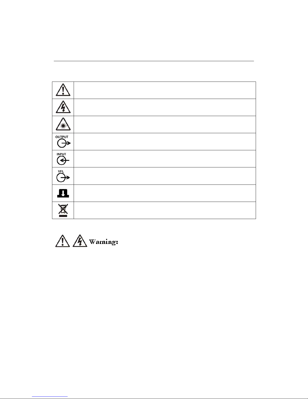
The international electrical symbols used on the instrument or in this manual are described below.
Warning or Caution: Risk of damage or destruction to equipment or software. See explanation in
the manual.
Warning: Risk of electric shock.
Warning: Class 1 and Class 2 Laser Products
Device Optical Measurement Output Connector
Device Optical Measurement Input Connector
Device Visual Fault Locator Output Connector
Optical Source / VFL Enable Buttons
Recyclable Electronic and Electrical Equipment (Do not dispose of in waste)
To avoid fire, electrical shock or personal injury read the safety information contained in the SCT2000 and SCT1500 Structured Cable
Testers User Manual.
Page 3
iii
Class 1 and Class 2 Laser Products
Under no circumstances should a user look directly into optical connectors. Some sources produce invisible radiation that can
permanently damage your eyes.
Under no circumstances should a user view the device’s optical connectors using magnification unless the device is detached from
the SCT series tester.
Always cover the device’s fiber optic output connector with the dust cap when not in use. The output source is active when the
device is powered.
Under no circumstances should a user look directly into the devices visual fault locator’s output. Long term exposure to the visual
fault locator’s output is potentially hazardous.
Under no circumstances should a user activate the visual fault locator without first connecting the visual fault locator to the link
under test.
If this product is used in a manner not specified by the manufacturer hazardous radiation exposure might result.
To prevent damage to the device and ensure result accuracy:
It is important that fiber optic patch cords, fiber under test and adapters are clean prior to testing. Always clean and inspect fiber
connectors prior to testing. Contamination can degrade optical performance, cause misalignment or cause back reflections leading to
poor results. Contamination can also damage the device and cable under test.
Always cover the device’s fiber optic connectors with the dust caps when not in use to reduce the possibility of contamination.
Do not use the device or accessories that appear damaged. Inspect the device and accessories before use.
Page 4

iv
CONTENTS
GETTING AQUAINTED ...........................................................................................................................................................................1
OVERVIEW............................................................................................................................................................................................1
UNPACKING.........................................................................................................................................................................................1
SCT_MMA Fiber Optic Adapter .......................................................................................................................................................1
SCT_SMA fiber Optic Adapter ..........................................................................................................................................................1
CONTACTING MEGGER....................................................................................................................................................................2
UNIT FEATURES..................................................................................................................................................................................3
Physical Features ................................................................................................................................................................................3
Device laser safety and operation labels .............................................................................................................................................4
Cleaning Connectors and Adapters ....................................................................................................................................................5
Cleaning SCT-MMA/SMA Fiber Optic and Bulkhead Connectors....................................................................................................6
Attaching SCT-MMA/SMA Fiber Optic Adapters ............................................................................................................................6
Multimode Testing Without Mandrels................................................................................................................................................6
Setting a Reference.............................................................................................................................................................................6
TEST MANAGEMENT ...............................................................................................................................................................................7
PROJECT FOLDERS .............................................................................................................................................................................7
Dual Media Projects ...........................................................................................................................................................................7
Managing Project Folders...................................................................................................................................................................8
CABLES ................................................................................................................................................................................................10
Managing Cables ..............................................................................................................................................................................10
TEST LIMITS .......................................................................................................................................................................................11
Viewing Test Limit ...........................................................................................................................................................................11
PREPARING TO TEST .............................................................................................................................................................................12
UNDERSTANDING TEST METHODS ............................................................................................................................................12
ESTABLISHING A FIBER OPTIC REFERENCE.............................................................................................................................12
Secondary Mode Reference Using Test Method B ...........................................................................................................................13
Loopback Mode Reference Using Test Method B............................................................................................................................14
CERTIFYING FIBER OPTIC CABLING.................................................................................................................................................15
AUTOTEST MENU .............................................................................................................................................................................15
Selecting a Project ............................................................................................................................................................................15
Changing a Circuit ID ......................................................................................................................................................................15
Certifying Duplex Cable Using Test Method B ................................................................................................................................16
Certifying Simplex Cable Using Test Method B ...............................................................................................................................17
INDIVIDUAL FIBER OPTIC CABLING TESTS ....................................................................................................................................18
INDIVIDUAL TEST MENU ...............................................................................................................................................................18
Individual Test Selections.................................................................................................................................................................18
Test Limit and Cable Type...............................................................................................................................................................18
Circuit ID .........................................................................................................................................................................................18
Individual Testing ............................................................................................................................................................................18
Viewing Results ................................................................................................................................................................................18
Light Source Mode...........................................................................................................................................................................19
Power Meter Mode ..........................................................................................................................................................................20
FIBER OPTIC CERTIFICATION RESULTS ...........................................................................................................................................21
RESULT SUMMARY............................................................................................................................................................................21
RESULT DETAIL ................................................................................................................................................................................21
Measurement Results .......................................................................................................................................................................21
VISUAL FAULT FINDER .........................................................................................................................................................................23
VFL OPERATION ...............................................................................................................................................................................23
MAINTENANCE AND SPECIFICATIONS ............................................................................................................................................24
SERVICE ADJUSTMENTS .................................................................................................................................................................24
CLEANING GUIDELINES ................................................................................................................................................................24
STORAGE ............................................................................................................................................................................................24
ENVIRONMENTAL CONDITIONS .................................................................................................................................................24
ACCESSORIES ...........................................................................................................................................................................................25
REPAIR AND WARRENTY......................................................................................................................................................................26
CERTIFICATION, COMPLIANCE AND REGULATORY INFORMATION ......................................................................................27
APPENDIX A: NAMING STANDARDS FOR TEST METHODS .........................................................................................................28
APPENDIX B: INDUSTRY STANDARD & APPLICATION TEST METHODS..................................................................................29
APPENDIX C: ALTERNATE TEST METHOD B...................................................................................................................................30
Page 5

v
FIGURES
Figure 1 Physical Features ...................................................................................................................................................................................................... 3
Figure 2 Secondary Mode Method B Reference Setting.................................................................................................................................................. 13
Figure 3 Loopback Mode Method B Reference Setting .................................................................................................................................................. 14
Figure 4 Secondary Mode Method B Certification Testing ............................................................................................................................................ 16
Figure 5 Loopback Mode Method B Certification Testing............................................................................................................................................. 17
Figure 6 Example of Secondary Light Source Mode.....................................................................................................................................19
Figure 7 Power Meter Modes .......................................................................................................................................................................20
Figure 8 Visual Fault Locator .......................................................................................................................................................................23
Figure 9 Alternate Method B Reference Setting ...........................................................................................................................................30
Figure 10 Alternate Method B Certification Testing.....................................................................................................................................31
Page 6

1
GETTING AQUAINTED
OVERVIEW
The SCT-MMA and SCT_SMA fiber optic adapters are used to convert the SCT series of testers into a fully compliant Tier 1 multimode
and singlemode fiber optic certification tester. The SCT fiber optic solution offers powerful capability and features including length
measurement, two-fiber, dual-wavelength loss measurements, single and bi-directional fiber measurements, power meter mode, light source
mode, Fiber Map and visual fault finder (VFL) capability.
Provides fully compliant Tier 1 fiber optic testing and reporting using Megger LCMD software.
When testing dual fibers the SCT measures length and measures loss on each fiber at two wavelengths. The SCT-MMA measures
loss at 850 nm and 1300 nm. The SCT-SMA measures loss at 1310 nm and 1550 nm.
Performs bi-directional testing on two fibers at two wavelengths without the need to exchange the Primary and Secondary units at
the end of the fiber optic link.
Switching between copper and fiber certification is faster and more reliable than any other solution by simply snapping in the desired
adapter.
Dual media projects store all necessary copper and fiber optic certification parameters in one project eliminating the need for the user
to modify certification parameters when switching from copper to fiber, or moving from one site to another.
Powerful capability and features including length measurement, two-fiber, dual-wavelength loss measurements, single and bi-
directional fiber measurements, power meter mode, light source mode, Fiber-Map, talk and visual fault finder (VFL) capability.
Integrated VFL is ideal for locating fiber optic trouble spots in jumper cables, distribution frames, splice strays, patch panels, cable
splice points and for tracing fiber runs.
UNPACKING
The SCT-MMA and SCT_SMA are packaged with the accessories listed below. Inspect your purchase for these items and any possible
damage due to shipping. If anything is missing or damaged contact the place of purchase immediately.
SCT_MMA Fiber Optic Adapter
(2) SCT-MMA Fiber Optic Adapters
(2) 62.5/125 µm multimode reference test cords, SC style connectors, 2 meter length
SCT-MMA/SMA Fiber Optic Adapter Users Manual CD
SCT_SMA fiber Optic Adapter
(2) SCT-MMA Fiber Optic Adapters
(2) 9/125 µm multimode reference test cords, SC style connectors, 2 meter length
SCT-MMA/SMA Fiber Optic Adapter Users Manual CD
Page 7

2
CONTACTING MEGGER
Visit the Megger web site at www.megger.com
.
Send email to:
USTechSupportGrp@megger.com
. For US time zone
DoverTechnicalSupport@megger.com
For UK time zone
To order accessories or get the location of the nearest Megger distributor or service center, call:
USA: 1 800 723 2861 from USA
+1 214 333 3201 from elsewhere
Canada: 1 800 297 9688
UK: +44 (0) 1304 502102
Full set of Megger addresses - see back of this manual
Page 8
3
UNIT FEATURES
The following sections introduce the fiber optic adapter’s basic features.
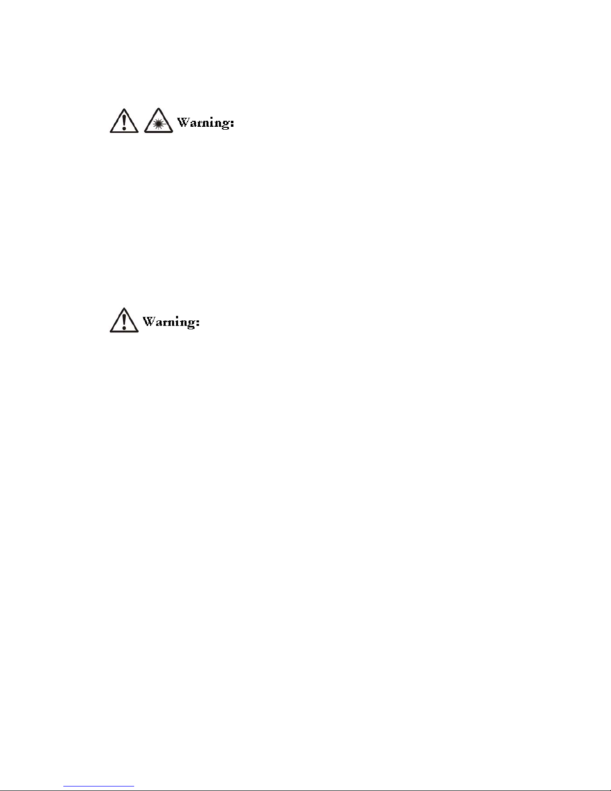
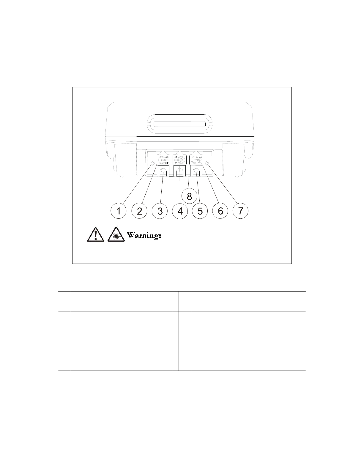
Physical Features
Figure 1 Physical Features
1. Light source mode enable button.
5.
Visual fault locator mode indication LED. This LED indicates
the VFL mode, continuous, blinking or off.
2.
SC style dual wave length fiber optic output (source)
connector with dust cap in place.
6.
Visual fault locator output connector with dust cap in place.
This universal connector accepts fiber optic connectors with a
2.5 mm ferrule.
3.
Fiber optic output (source) mode indication LED. This
LED is red for 850/1310 nm wave lengths and green
for 1300/1550 nm wave lengths.
7. Visual fault locater enable button.
4.
SC style fiber optic input (detector) connector with dust
cap in place.
8. Device Laser Safety and operation label (shown below)
Under no circumstances should a user look directly into the devices optical output connectors. Some
sources produce invisible radiation that can permanently damage an eye.
Page 9
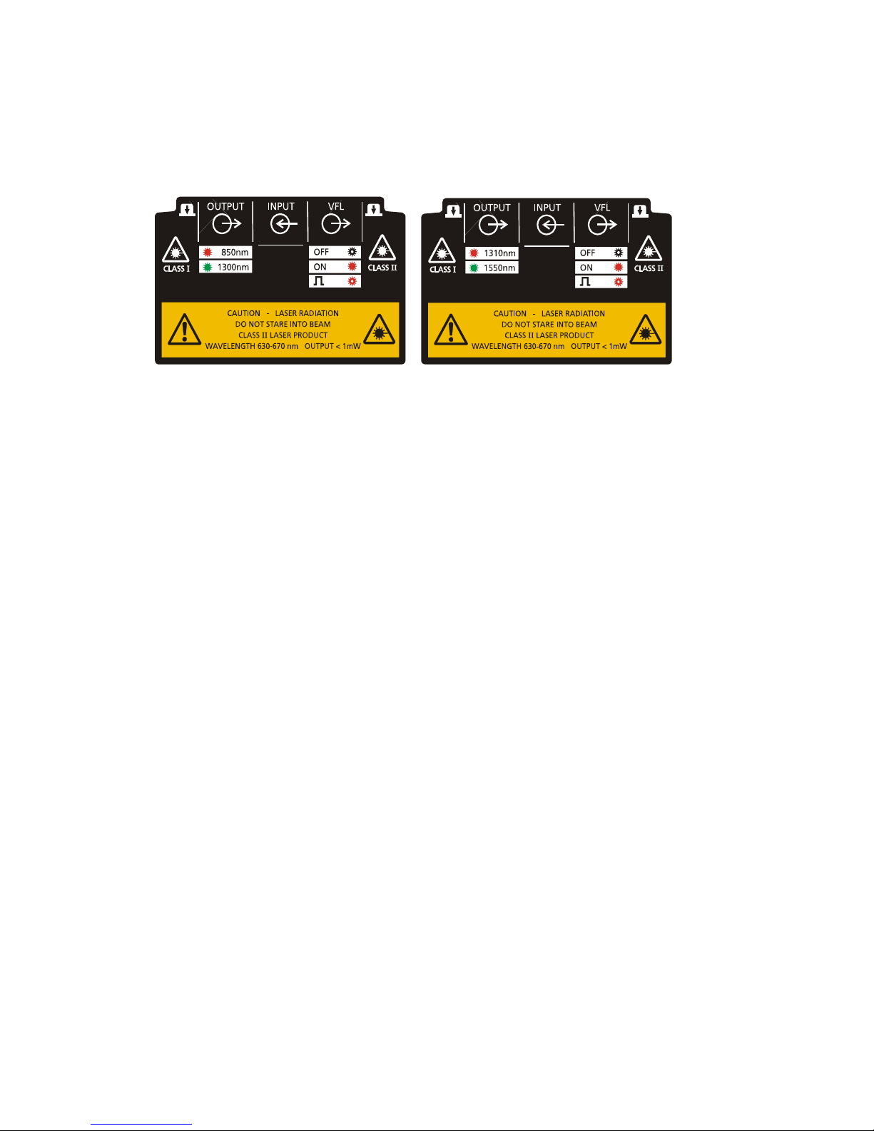
4
Device laser safety and operation labels
SCT-MMA multimode and SCT-SMA singlemode device label
Page 10

5
Getting started
Cleaning Connectors and Adapters
It is important that fiber optic patch cords, fiber under test and adapters are clean prior to testing. Always clean and inspect fiber
connectors prior to testing. Fiber contamination can scratch the glass surfaces, degrade optical power, cause misalignment or cause back
reflections leading to possible instability in a laser sources.
Cleaning Patch Cord and Fiber Connector End Faces
Megger recommends using a cartridge or pocket style dry cleaner to clean fiber optic cable connector end faces. Follow the cartridge or
pocket style dry cleaner manufacturer’s directions.
Alternate Dry Cleaning Method Using Lint-Free Wipes
Ensure all LED and Laser sources are off
Fold the wipe into a square about 4 to 8 layers thick.
Wipe the end face in a figure 8 motion, applying light pressure only on the center portion of the wipe. Heavy pressure can cause
scratches and more contamination.
Repeat the figure 8 motion on another clean portion of the wipe.
Properly dispose of the wipe. Never reuse a wipe.
Alternate Wet Cleaning Method Using Lint-Free Wipes
If a dry cleaning procedure does not remove the dirt from the fiber end face, then try the wet cleaning method. When using isopropyl
alcohol it is important to completely remove all of the alcohol from the end face. Residual liquid alcohol can trap loose dirt. Isopropyl
alcohol that evaporates slowly can leave residual material making it more difficult to clean off without another wet cleaning.
Ensure all LED and Laser sources are off
Fold the wipe into a square about 4 to 8 layers thick.
Moisten one section of the wipe with one drop of 99% pure isopropyl alcohol, leaving a portion of the wipe dry.
Wipe the end face in the alcohol moistened portion of the wipe with a figure 8 motion, applying light pressure only. Heavy pressure
can cause scratches and more contamination.
Immediately wipe the end face in the dry portion of the wipe with a figure 8 motion, applying light pressure only. Heavy pressure
can cause scratches and more contamination.
Properly dispose of the wipe. Never reuse a wipe.
Cleaning Connector Adapters
When using isopropyl alcohol it is important to completely remove all of the alcohol from the end face. Residual liquid alcohol can trap
loose dirt. Isopropyl alcohol that evaporates slowly can leave residual material making it more difficult to clean off without another wet
cleaning.
Place one drop of 99% pure isopropyl alcohol on an appropriate size swab, do not over saturate the swab.
Lightly insert the dampened swab into the connector.
Turn the swab several complete revolutions in the same direction.
Remove the dampened swab and insert a second dry second dry swab to remove any alcohol that remains.
Turn the dry swab several complete revolutions in the same direction.
Properly dispose of the wet and dry swab. Never reuse a swab.
Page 11
6
Cleaning SCT-MMA/SMA Fiber Optic and Bulkhead Connectors
The best method for keeping the SCT-MMA/SMA and bulkhead connectors clean is to cover the connectors when not in use and only
insert clean fiber optic patch cord connectors. Cleaning the SCT-MMA/SMA and bulkhead connectors should always be followed by
inspection to determine results.
Dry Cleaning Method
Megger recommends using the dry clean method for cleaning SCT-MMA/SMA and Bulkhead connectors.
Ensure all LED and Laser sources are off
Insert the clean lint-free 2.5 mm swab into the connector.
Turn the swab several complete revolutions in the same direction.
Properly dispose of the swab. Never reuse a swab.
Repeat the cleaning process as necessary.
Wet Cleaning Method
If a dry cleaning procedure does not remove the dirt from the SCT-MMA/SMA fiber optic connectors, then try the wet cleaning method.
When using isopropyl alcohol it is important to completely remove all of the alcohol from the end face. Residual liquid alcohol can trap
loose dirt. Isopropyl alcohol that evaporates slowly can leave residual material making it more difficult to clean off without another wet
cleaning.
Ensure all LED and Laser sources are off
Place one drop of 99% pure isopropyl alcohol on a 2.5 mm swab, do not over saturate the swab.
Lightly insert the dampened swab into the connector.
Turn the swab several complete revolutions in the same direction.
Remove the dampened swab and insert a second dry second dry swab to remove any alcohol that remains.
Turn the dry swab several complete revolutions in the same direction.
Properly dispose of the wet and dry swab. Never reuse a swab.
Attaching SCT-MMA/SMA Fiber Optic Adapters
The SCT-MMA/SMA fiber optic adapters may be attached or removed prior to or after completing a test. Removing an adapter will cause
the SCT to return to the main menu in preparation for the attachment of a different adapter. The SCT may remain powered on when
attaching or removing a SCT-MMA/SMA fiber optic adapter.
Multimode Testing Without Mandrels
The SCT-MMA fiber optic adapter does not require an external mandrel when testing multimode fiber. The SCT-MMA fiber optic adapter
uses a unique LED source and internal mandrel to comply with TIA/EIA-568-B.1 and ISO/IEC TR 14763-3 standards.
Setting a Reference
Setting a reference establishes the zero loss power and zero length distance for all future measurements. Setting a reference also removes
additional losses due to reference patch cords and adapters that should not be included in the measurement. Therefore properly setting a
reference is necessary for obtaining accurate results.
Establish a fiber optic reference only after the SCT Primary and Secondary units and the SCT-MMA/SMA fiber optic adapters
have been on for five minutes. Allow additional time for the adapter to reach ambient temperature if the adapters have been
stored above or below ambient temperature.
The reference measurement is invalidated if the reference patch cord is disconnected from the SCT_MMA/SMA fiber optic
adapter. Disconnecting and re-connecting a reference patch cord will alter the optical characteristics resulting in a different
reference loss power.
Establish a new reference:
Anytime the SCT-MMA/SMA adapters are attached.
Anytime the reference patch cords are disconnected from the SCT-MMA/SMA adapters.
Anytime negative loss or length results are obtained.
The SCT will request a new reference:
After a 24 hour period has elapsed since the last reference
Anytime a different fiber optic is attached to the primary or secondary SCT.
Anytime the test mode is switched from loopback to secondary or secondary to loopback.
Anytime the test method is changed.
Page 12

7
TEST MANAGEMENT
Managing the test environment of the SCT is all organized under the HOME page using the “Manage” functions. These functions allow
the user to manage Projects, Cables, Test Limits and Stored Results.
PROJECT FOLDERS
The Project Folder contains all certification testing parameters, results and information about a specific test site. A project folder is created
by selecting the required certification testing parameters and then saving the selections in a project folder. Saving the certification testing
parameters in the project folder ensures that the selected test parameters are used at a project site.
When certifying you can select an existing Project Folder, edit an existing Project Folder, or create a new Project Folder for your
certification needs. If Project Folder parameters need to be changed then the changes are made using the Project Editor option in the
Manage Project Folders menu. If a new Project Folder is required it is created using the Create Project option also in the Manage Project
Folders menu.
Dual Media Projects
SCT software versions 2.00 and higher support dual media projects. Dual media projects allow the user to store copper and fiber test
parameters in a single project. When a dual media project is selected the SCT automatically loads copper parameters if a channel or
permanent link adapter is attached or fiber parameters if a fiber optic adapter is attached. Dual mode projects make switching between
copper and fiber certification faster and more reliable than any other solution. Dual media projects are created using the create project
process to establish the first set of test parameters and then the edit project process to create test parameters for a second media type.
Copper projects require the following test parameters:
Field Description
Project Determines the project name.
Media The media type selection twisted pair, singlemode fiber or multimode fiber determines what test
parameters are required and what adapter is expected.
Test Limit The test limit selection determines what tests to perform and how to evaluate the results.
Cable The cable type selection determines what cable name and parameters to use for testing.
Circuit ID The circuit id generates a list of circuit id’s that identify the cable test results
Location The location selection determines where the project and results are stored either internally or
externally.
Comment The comment field allows the user to enter a comment about the project.
Page 13

8
Fiber optic projects require the following test parameters:
Field Description
Project Determines the project name.
Media The media type selection twisted pair, singlemode fiber or multimode fiber determines what test
parameters are required and what adapter is expected.
Test Limit The test limit selection determines what tests to perform and how to evaluate the results.
Cable The cable type selection determines what cable name and parameters to use for testing.
Circuit ID The circuit id generates a list of circuit id’s that identify the cable test results
Location The location selection determines where the project and results are stored either internally or
externally.
Secondary Setup
The secondary setup selection determines the mode of testing. Secondary mode tests dual fiber using
the primary and secondary units. Loopback mode tests a single fiber using only the primary unit.
Bi-Directional Fiber
Selecting bi-directional testing will measure and report loss on each fiber at two wavelengths in both
directions. When selected the user will be asked to swap fibers on both adapters. Do not disconnect
the reference cords from the adaptors, instead disconnect and swap the fibers under test at the first
adapters.
Number of Adapters
Selection allowing the user to select the number of adapters in the link. Limits that depend upon the
number of adapters will use this number to calculate the loss budget.
Number of Splices
Selection allowing the user to select the number of splices in the link. Limits that depend upon the
number of splices will use this number to calculate the loss budget.
Connector Type
The connector type is fixed to SC.
Test Method
The test method selection determines the testing method.
Refractive Index
The refractive index selection of “Default” sets the refractive index to values provided by the cable
manufacturer for the selected fiber optic cable. A setting of “User Defined” allows the user to set the
refractive index.
850 nm / 1310 nm
The refractive index value of either the multimode 850 nm wave length or the singlemode 1310 nm
wave length.
1310 nm / 1550 nm
The refractive index value of either the multimode 1300 nm wave length or the singlemode 1550 nm
wave length.
Comment The comment field allows the user to enter a comment about the project.
Managing Project Folders
Functions for viewing, editing, creating and deleting projects are accessed at the “Home” menu by selecting “Projects” in the manage
window. Grouping all project functions and parameters into a single menu reduces user effort and increases test parameter reliability.
View a Project Folder
:
The view process is used to view test parameters of an existing project.
1. Select “Projects” from the “HOME” menu using the navigation keys and press [ENTER].
2. Select “View Project” and press [ENTER].
3. Navigate to the desired project and press [ENTER].
4. Select “Media” type to view the appropriate copper of fiber test parameters
Edit a Project Folder
:
The edit process is used to change test parameters of an existing project, or add test parameters for a second media type such as fiber of
twisted pair. The edit process always begins on page one. Press the right arrow to move to the next page and the left arrow to move to the
previous page.
1. Select “Projects” from the “HOME” menu using the navigation keys and press [ENTER].
2. Select “Edit Project” and press [ENTER].
3. Navigate to the desired project and press [ENTER].
4. Select “Media” type to display the desired copper or fiber test parameters
5. Navigate to the desired test parameter field and press [ENTER]. Change the field as required.
6. When complete navigate to and highlight the option to “Save” and press [ENTER].
Create a Copper Project Folder
:
Creating a copper project spans two menu windows. The process always begins on page one. Press the right arrow to move to the next
page and the left arrow to move to the previous page.
Page 14

9
Page 1
1. Select “Projects” from the “HOME” menu using the navigation keys and press [ENTER].
2. Select “Create Project” and press [ENTER].
3. Create a Project Name - Navigate to the project name field and press [ENTER]. Using the editor create a new project name.
When complete navigate to the Save hyperlink and press [ENTER].
4. Select a Media type- Navigate to the Media field and press [ENTER]. Using the navigation keys highlight the “twisted Pair”
selection and press [ENTER].
5. Select a Test Limit - Navigate to the test limit field and press [ENTER]. Using the navigation keys highlight the desired test
limit and press [ENTER].
6. Select a Cable Type - Navigate to the cable field and press [ENTER]. Using the navigation keys highlight the desired cable type
and press [ENTER].
7. Create a Circuit ID - Navigate to the Circuit ID and press [ENTER]. Refer to the section titled Circuit ID for more
information.
Select a Circuit ID Type - Navigate to the Circuit ID Type and press [ENTER]. Use the navigation keys to select the
desired Circuit ID type and press [ENTER].
Select a Circuit ID Form - Navigate to the Circuit ID Form and press [ENTER]. Use the navigation keys to select the
desired Circuit ID Form and press [ENTER].
To establish or change the start Circuit ID, highlight the Start CID and press [ENTER]. Use the editor to create the
desired circuit ID.
To establish or change the stop Circuit ID, highlight the Stop CID and press [ENTER]. Use the editor to create the
desired circuit ID.
To preview Circuit ID list use the navigation keys and highlight the “Preview Circuit ID” hyperlink and press
[ENTER].Press the BACK key to return.
To save the Circuit ID use the navigation keys to highlight the “Save” hyperlink and press [ENTER].
8. Select a Location - Navigate to the location field and press [ENTER]. Using the navigation keys highlight the desired storage
location and press [ENTER].
Page 2
Press the right arrow to move to page 2.
9. Add a Comment – Navigate to the Comment field and press [ENTER]. Using the editor create a comment.
Create a Fiber Optic Project Folder
:
Creating a fiber optic project spans three menu windows. The process always begins on page one. Press the right arrow to move to the
next page and the left arrow to move to the previous page.
Page 1
1. Select “Projects” from the “HOME” menu using the navigation keys and press [ENTER].
2. Select “Create Project” and press [ENTER].
3. Create a Project Name - Navigate to the project name field and press [ENTER]. Using the editor create a new project name.
When complete navigate to the Save hyperlink and press [ENTER].
4. Select a Media type- Navigate to the Media field and press [ENTER]. Using the navigation keys highlight either “Multimode”
or “Singlemode” option and press [ENTER].
5. Select a Test Limit - Navigate to the test limit field and press [ENTER]. Using the navigation keys highlight the desired test
limit and press [ENTER].
6. Select a Cable Type - Navigate to the cable field and press [ENTER]. Using the navigation keys highlight the desired cable type
and press [ENTER].
7. Create a Circuit ID - Navigate to the Circuit ID and press [ENTER]. Refer to the section titled Circuit ID for more
information.
Select a Circuit ID Type - Navigate to the Circuit ID Type and press [ENTER]. Use the navigation keys to select the
desired Circuit ID type and press [ENTER].
Select a Circuit ID Form - Navigate to the Circuit ID Form and press [ENTER]. Use the navigation keys to select the
desired Circuit ID Form and press [ENTER].
To establish or change the start Circuit ID, highlight the Start CID and press [ENTER]. Use the editor to create the
desired circuit ID.
To establish or change the stop Circuit ID, highlight the Stop CID and press [ENTER]. Use the editor to create the
desired circuit ID.
To preview Circuit ID list use the navigation keys and highlight the “Preview Circuit ID” hyperlink and press
[ENTER].Press the BACK key to return.
To save the Circuit ID use the navigation keys to highlight the “Save” hyperlink and press [ENTER].
10. Select a Location - Navigate to the location field and press [ENTER]. Using the navigation keys highlight the desired storage
location and press [ENTER].
Page 2
Press the right arrow to move to page 2.
11. Select Secondary Setup (Mode) – Navigate to the secondary setup field and press [ENTER]. Using the navigation keys
highlight the desired mode and press [ENTER].
12. Select Bi-directional Fiber – Navigate to the bi-directional fiber field and press [ENTER]. Using the navigation keys highlight
the desired mode and press [ENTER].
Page 15

10
Selecting bi-directional testing will measure and report loss on each fiber at two wavelengths in both directions. When
selected the user will be asked to swap fibers on both adapters. Do not disconnect the reference cords from the adaptors,
instead disconnect and swap the fibers under test at the first adapters.
13. Select Number of Adapters – Navigate to the number of adapters field and press [ENTER]. Using the navigation keys select
the desired number and press [ENTER].
Limits that depend upon the number of adapters will use this number to calculate the loss budget. Selecting a test
method will change the number of adapters. Refer to “Select Test Method” below.
14. Select Number of Splices – Navigate to the number of splices field and press [ENTER]. Using the navigation keys select the
desired number and press [ENTER].
Limits that depend upon the number of splices will use this number to calculate the loss budget. Selecting a test Method
will change the number of adapters. Refer to “Select Test Method” below.
15. Connector type is fixed to SC
16. Select Test Method – Navigate to the test method field and press [ENTER]. Using the navigation keys highlight the desired
method and press [ENTER].
Selecting a test method informs the SCT what type of reference method is being used.
Selecting a test method will overwrite the current value for number of adapter’s and set the following default values:
o Method A = 1 adapter
o Method B = 2 adapters
o Method C = 0 adapters.
If the default number of adapters is incorrect then edit the number of adapters after selecting the method.
Page 3
Press the right arrow to move to page 3.
17. Select Refraction Index mode – Navigate to the refraction index field and press [ENTER]. Using the navigation keys highlight
the desired mode and press [ENTER].
“Default” sets the refractive index to values provided by the cable manufacturer for the selected fiber optic cable.
“User Defined” allows the user to set the refractive index
18. 850 / 1310 nm – Navigate to the refraction index 850 / 1300 nm value field and press [ENTER]. Using the editor set the
refractive index, when complete navigate to “Done” and press [Enter]navigation keys highlight the desired mode and press
[ENTER].
19. 1300 / 1550 nm – Navigate to the refraction index 1300 / 1550 nm value field and press [ENTER]. Using the editor set the
refractive index, when complete navigate to “Done” and press [Enter]
20. Add a Comment – Navigate to the Comment field and press [ENTER]. Using the editor create a comment.
Delete a Project Folder
:
The delete process is used to delete projects from internal or external SCT memory. To protect the user from accidental deleting results
the SCT will not delete a project that contains results. Delete all saved results in a project before deleting the project.
1. Select “Projects” from the “HOME” menu using the navigation keys and press [ENTER].
2. Select “Delete Project” and press [ENTER].
3. Select the project to view and press [ENTER].
4. Confirm the action and press [ENTER].
CABLES
SCT manages a library of pre-defined manufacturer and user created cables. The user may view all cables and edit, delete and create
custom cables for use in certification. Cables contained in the library are selected from the manage project function.
Managing Cables
(MGB) need to define added tree structure
View Cable
:
1. Using the navigation keys select “Cables” from the “HOME” menu, under the “Manage” window and press [ENTER].
2. Select “View Cable” and press [ENTER].
3. Using the navigation keys select manufacturer supplied or user supplied cable and press [RIGHT ARROW].
4. Using the navigation keys select the cable media type press [RIGHT ARROW].
5. Using the navigation keys select the cable supplier name and press [RIGHT ARROW].
6. Using the navigation keys select the desired cable and press [ENTER].
7.
Edit Cable
:
1. Using the navigation keys select “Cables” from the “HOME” menu, under the “Manage” window and press [ENTER].
2. Select “Edit Cable” and press [ENTER].
3. Using the navigation keys select user supplied cable and press [RIGHT ARROW].
4. Using the navigation keys select the cable media type press [RIGHT ARROW].
5. Using the navigation keys select the cable supplier name and press [RIGHT ARROW].
6. Using the navigation keys select the desired cable and press [ENTER].
7. Change the cable parameters then navigate to “Save Cable” and press [ENTER].
Page 16

11
Create Cable
:
1. Using the navigation keys select “Cables” from the “HOME” menu, under the “Manage” window and press [ENTER].
2. Select “Create Cable” and press [ENTER].
3. Select a cable media type and press [ENTER].
4. Enter the cable parameters then navigate to “Save Cable” and press [ENTER].
Delete Cable
:
1. Using the navigation keys select “Cables” from the “HOME” menu, under the “Manage” window and press [ENTER].
2. Select “Delete Cables” and press [ENTER].
3. Using the navigation keys select user supplied cable and press [RIGHT ARROW].
4. Using the navigation keys select the cable media type press [RIGHT ARROW].
5. Using the navigation keys select the cable supplier name and press [RIGHT ARROW].
6. Using the navigation keys select the desired cable and press [ENTER].
TEST LIMITS
SCT manages a standards library of pre-defined test limits for certification. The user may view the library of selectable test limits but may
not view the details of a test limit or modify the test limits. Test limits contained in the library are selected from the Manage Project
function.
Viewing Test Limit
1. Using the navigation keys select “Test Limit” from the “HOME” menu, under the “Manage” window and press
[ENTER].
2. Using the navigation keys select user “Manufacturers” and press [RIGHT ARROW].
3. Using the navigation keys select the tests limit media type press [RIGHT ARROW].
4. Using the navigation keys select the test limits supplier name and press [RIGHT ARROW].
5. Using the navigation keys open the desired standard body type then navigate to the desired test limit type and press
[RIGHT ARROW] to see which test limits are available.
Page 17

12
PREPARING TO TEST
UNDERSTANDING TEST METHODS
Test method defines how the reference power measurement is performed. Test methods are defined by the standards bodies. The
standards do not use consistent naming to define the same test methods. In this manual the methods are referred to as Test Method A, B
and C. Please refer to Appendix A for some common standard test method naming and defined method use.
Test Method A – (two reference cord measurement)
Setting a reference using test method A requires two reference patch cords and one adapter. The measurement results include
the loss of the cable plant and the loss of one connection.
Test Method B – (one reference cord measurement)
Setting a reference using test method B requires one reference patch cords and no adapters. The measurement results include
the loss of the cable plant and the loss of two connections.
Test Method C – (three reference cord measurement)
Setting a reference using test method C requires three reference patch cords, and two adapters. The measurement results
include the loss of the cable plant only.
If you are testing fiber optic links with connectors other than SC style, refer to Appendix B for the Modified Test Method B that produces
Test Method B results.
ESTABLISHING A FIBER OPTIC REFERENCE
Setting a fiber optic reference establishes the zero loss power and zero length distance for all future measurements. Setting a reference also
removes additional losses due to reference patch cords and adapters that should not be included in the measurement. Therefore properly
setting a reference is necessary for obtaining accurate results.
Establish a fiber optic reference only after the SCT Primary and Secondary units and the SCT-MMA/SMA fiber optic adapters
have been on for five minutes. Allow additional time for the adapter to reach ambient temperature if the adapters have been
stored above or below ambient temperature.
The reference measurement is invalidated if the reference patch cord is disconnected from the SCT_MMA/SMA fiber optic
adapter. Disconnecting and re-connecting a reference patch cord will alter the optical characteristics resulting in a different
reference loss power.
Establish a new reference:
Anytime the SCT-MMA/SMA adapters are attached.
Anytime the reference patch cords are disconnected from the SCT-MMA/SMA adapters.
Anytime negative loss or length results are obtained.
The SCT will request a new reference:
After a 24 hour period has elapsed since the last reference
Anytime a different fiber optic is attached to the primary or secondary SCT.
Anytime the test mode is switched from loopback to secondary or secondary to loopback.
Anytime the test method is changed.
Page 18

13
Secondary Mode Reference Using Test Method B
If setting a Method B reference using the Megger provided duplex reference cords use both cords to eliminate removing one cord from the
adapter and invalidation the reference. If the fiber optic link uses non-SC style connectors refer to Appendix B for establishing a reference
using the modified test method B setup.
1. Attach either the SCT-MMA or SCT_SMA fiber optic adapters
2. Using the navigation keys select “Autotest” from the “HOME” menu and press [ENTER].
3. Select the desired project and press [ENTER].
4. Using the navigation keys select “Set Reference” from the “HOME” menu and press [ENTER].
5. Verify the fiber optic reference cords are attached per the displayed reference configuration.
6. Press the [TEST] button. If the fiber optic link is incorrect the SCT will display the Fiber Map to prompt a correction.
7. When the reference measurement is complete the SCT will display the measured power and the option to set the reference
patch cord lengths.
8. Verify the measured power, and set the patch cord lengths if desired, then press [ENTER]
9. Verify the fiber optic reference cords will be attached per the displayed measurement configuration and press [ENTER]
SCT PRIMARY
SCT SECONDARY
Do not disconnect the reference cords from the output
connectors. Disconnecting the reference cords from
the output connectors will invalidate the reference setting.
Caution
Duplex SC - SC style fiber
optic referen ce cords
Figure 2 Secondary Mode Method B Reference Setting
Page 19

14
Loopback Mode Reference Using Test Method B
Setting a Method B reference using the Megger provided duplex reference cord. If the fiber optic link uses non-SC style connectors refer
to Appendix B for establishing a reference using the modified test method B setup.
1. Attach either the SCT-MMA or SCT_SMA fiber optic adapter
2. Using the navigation keys select “Autotest” from the “HOME” menu and press [ENTER].
3. Select the desired project and press [ENTER].
4. Using the navigation keys select “Set Reference” from the “HOME” menu and press [ENTER].
5. Verify the fiber optic reference cord is attached per the displayed reference configuration.
6. Press the [TEST] button. If the fiber optic link is incorrect the SCT will display the Fiber Map to prompt a correction.
7. When the reference measurement is complete the SCT will display the measured power and the option to set the reference
patch cord lengths.
8. Verify the measured power, and set the patch cord lengths if desired, then press [ENTER]
9. Verify the fiber optic reference cords will be attached per the displayed measurement configuration and press [ENTER]
SCT PRIMARY
`
Duplex SC - SC style fiber
optic reference cord
Do not disconnect the reference cord from the output
connector. Disconnecting the r eference cord from the
output connector will invalidate the reference setting.
Caution
Figure 3 Loopback Mode Method B Reference Setting
Page 20

15
CERTIFYING FIBER OPTIC CABLING
Certification requires that the appropriate project is selected and a reference is established prior to testing.
The reference measurement is invalidated if the reference patch cord is disconnected from the SCT_MMA/SMA fiber optic
adapter. Disconnecting and re-connecting a reference patch cord will alter the optical characteristics resulting in a different
reference loss power.
AUTOTEST MENU
All certification testing tasks such as selecting a Project, changing a Circuit ID, starting an Autotest, test result notification, saving results
and viewing results are managed from the Autotest menu, simplifying testing.
1. Using the navigation keys select “Autotest” from the “Home” menu and press [ENTER].
Selecting a Project
The SCT will default to the last used project and compare the project test parameters to the attached adapter. If the adapter media type is
not defined in the current project, the SCT will request the selection of an appropriate project. The SCT will only allow the selection of
projects that match the adapter media type in order to eliminate test parameter errors.
1. Using the navigation keys select “Project” from the “Autotest” menu and press [ENTER].
2. Using the navigation keys select the desired Project and press [ENTER].
If a new project is required, or the existing Project needs to be changed, use the Manage Project feature described in the “Project Folders”
section.
Changing a Circuit ID
The SCT will default to the next available Circuit ID defined in the Project. If another Circuit ID in the series is required then:
1. Using the navigation keys select “Circuit ID” from the “Autotest” menu and press [ENTER].
2. Depending upon the Circuit ID type defined in the Project either use the navigation keys to select the desired Circuit ID from the list
and press [ENTER], or edit the Circuit ID, select the soft key “Done” and press [ENTER].
If the Circuit ID series needs to be changed, use the Manage Project feature described in the “Project Folders” section.
Page 21

16
Certifying Duplex Cable Using Test Method B
All necessary certification test information is displayed and all required certification tasks are available from the Autotest menu to maximize
productivity. If the fiber optic link uses non-SC style connectors refer to Appendix B for certifying using the modified test method B
setup.
To begin certifying links:
1. Verify that the Project settings are correct.
2. Attach the correct adaptors for the link type under test.
3. Attach the SCT Primary and Secondary devices to the ends of the link.
4. Press the [TEST] key. The [ESC] key can be pressed to stop the test at any time.
5. During the test the Circuit ID can be changed in order to save time. If the Circuit ID is correct no action is needed.
6. When finished the overall test result is displayed. At this time you may:
Change the Circuit ID
Save the result
View the result
Run another Autotest
Exit the Autotest Menu.
SCT PRIMARY
SCT SECONDARY
Fibre optic link
or spool under
test
Do not disconnect the reference cords from the output
connectors. Discon necting the reference c ords from
the output connectors will invalidate the reference setting.
Caution
Duplex SC - SC style fiber
optic reference cord
Duplex SC - SC style fiber
optic reference cord
Figure 4 Secondary Mode Method B Certification Testing
Saving Results
Saving certification results stores all of the necessary data for certification testing compliance and report generation, in accordance with
industry standards.
1. Navigate to the “Save Result” option and press the [ENTER] key.
Viewing Results
Viewing results displays the certification results in summary, detailed or graphic formats. Refer to the chapter named Fiber Optic
Certification Results for more details. To view results:
1. Navigate to the “View Result” option and press the [ENTER] key.
Page 22

17
Certifying Simplex Cable Using Test Method B
All necessary certification test information is displayed and all required certification tasks are available from the Autotest menu to maximize
productivity. If the fiber optic link uses non-SC style connectors refer to Appendix B for certifying using the modified test method B
setup.
To begin certifying links:
1. Verify that the Project settings are correct.
2. Attach the correct adaptors for the link type under test.
3. Attach the SCT Primary and Secondary devices to the ends of the link.
4. Press the [TEST] key. The [ESC] key can be pressed to stop the test at any time.
5. During the test the Circuit ID can be changed in order to save time. If the Circuit ID is correct no action is needed.
6. When finished the overall test result is displayed. At this time you may:
Change the Circuit ID
Save the result
View the result
Run another Autotest
Exit the Autotest Menu.
Duplex SC - SC style fiber
optic reference cord
Fibre optic link
or spool under
test
Do not disconnect the reference cord from the output
connector. Disconnecting the reference cord from the
output connector will invalidate the reference setting.
Caution
Figure 5 Loopback Mode Method B Certification Testing
Saving Results
Saving certification results stores all of the necessary data for certification testing compliance and report generation, in accordance with
industry standards.
1. Navigate to the “Save Result” option and press the [ENTER] key.
Viewing Results
Viewing results displays the certification results in summary, detailed or graphic formats. Refer to the chapter named Fiber Optic
Certification Results for more details. To view results:
2. Navigate to the “View Result” option and press the [ENTER] key.
Page 23

18
INDIVIDUAL FIBER OPTIC CABLING TESTS
Individual tests require that the appropriate project is selected and a reference is established with exception of the light source and power
meter prior to testing.
INDIVIDUAL TEST MENU
All individual testing tasks such as selecting a test and starting a test are managed from the Individual Test menu simplifying testing.
1. Using the navigation keys select “Individual Test” from the “Home” menu and press [ENTER].
Individual Test Selections
Fiber Map
The fiber map option displays a graphical representation of the fiber optic ca ble connected to the primary and secondary fiber
optic adapter output and input connectors.
Loss
The loss option performs a certification loss measurement.
Length
The length option performs a certification length measurement.
Power
The power option performs a power measurement and reports back measured power in dBm and Watts.
Light Source
The light source option enables the dual wave length light source mode.
Power Meter
The power meter option enables the power meter mode capable of measuring optical power at 850, 1300, 1310 and 1550 nm
wave lengths.
Test Limit and Cable Type
The test limit and cable type are defined by the currently selected Project. The test limit and cable type are changed by selecting a different
project from the Autotest menu and returning to the Individual Test menu.
Circuit ID
Individual tests cannot be saved so the Circuit ID has no effect on the test.
Individual Testing
All necessary individual test information is displayed and all required individual testing tasks are available from the Individual Test menu to
maximize productivity. To begin testing:
1. Verify that the test settings are correct.
2. Attach the correct adaptors for the link type under test.
3. Attach the SCT Primary device and Secondary device if needed to the ends of the link.
4. Select the measurement type
5. Press the [TEST] key. The [ESC] key can be pressed to stop the test at any time.
6. When finished the individual test result is displayed. At this time you may:
View the result
Run another Individual Test
Exit the Individual Test Menu.
Viewing Results
Viewing results displays the certification results in summary, detailed or graphic formats. Refer to the chapter named Fiber Optic
Certification Results for more details. To view results:
1. Navigate to the “View Result” option and press the [ENTER] key.
Page 24

19
Light Source Mode
The light source mode can be enabled on the primary device by selecting light source mode in the individual measurement menu or by
pressing the light source enable button on the SCT-MMA or SCT_SMA fiber optic adapter.
The light source mode can be enabled on the secondary by pressing the light source enable button on the SCT-MMA or SCT_SMA fiber
optic adapter.
The first press of the light source button on the adapter will turn on the multimode 850nm or singlemode 1310 nm wavelength as indicated
by a RED light source mode LED. Pressing the light source mode button a second time will turn on the multimode 1300 nm or
singlemode 1550 nm wavelength as indicated by a GREEN light source mode LED. Pressing the light source mode button a third time
will turn off the light source mode and return the adapter to normal operation.
SCT PRIMARY
SCT SECONDARY
Simplex SC - SC style
fiber optic cord
Figure 6 Example of Secondary Light Source Mode
Page 25

20
Power Meter Mode
The power meter mode is enabled on the primary device by selecting power meter in the individual measurement menu. The power meter
mode continuously monitors and reports optical power.
SCT PRIMARY
O
U
T
P
U
T
O
U
T
P
U
T
Fibre optic link
or spool under
test
Simplex SC - SC style
fiber optic cord
Figure 7 Power Meter Modes
Page 26

21
FIBER OPTIC CERTIFICATION RESULTS
The SCT Autotest carries out all tests required by industry standards. If a test is not applicable to the selected test standard the test will be
marked ‘informative’ and will not be evaluated for certification.
RESULT SUMMARY
The result summary showing all measurements in summary format is displayed first when viewing results. The result summary display is
formatted for easy viewing of overall result performance displaying all certification result information including each measurement’s worst
case margin and the fiber it occurred on. Result details are available by highlighting the desired result and pressing [ENTER].
RESULT DETAIL
Result detail displays an individual measurement’s detail.
1. Using the navigation keys select the measurement of interest from the result summary menu and press [ENTER].
The result detail display is formatted for easy viewing of individual measurement result performance, displaying all measurement result
information.
Measurement Results
Loss
Loss results always refer to the fiber connected to the primary unit’s fiber optic adapter input and output connector at the end of a test.
Simplex fiber loss results (non-Bi-Directional)
These loopback mode results are obtained at two wave lengths and measured in one direction on the one fiber.
1. Loss results are obtained from the input fiber at the end of the test and labeled “Primary Input Fiber”.
The direction of the measurement was from the output connector to the input connector and labeled as “Input <
Output”.
Simplex fiber loss results (Bi-Directional)
These loopback mode results are obtained at two wave lengths and measured in two directions on the one fiber.
1. Both Loss results are obtained from the input fiber at the end of the test and labeled “Primary Input Fiber”.
The direction of the first measurement was from the input connector to the output connector and labeled as “Input >
Output”.
This direction occurs because the fiber was swapped between the first and second test and the results always refer
to the input and output connector at the end of a test.
The direction of the second measurement was from the output connector to the input connector and labeled as “Input <
Output”.
Duplex fiber loss results (non-Bi-Directional)
These secondary mode results are obtained at two wave lengths and measured in one direction on each fiber.
1. Loss results obtained from the input fiber at the end of the test are labeled “Primary Input Fiber”.
The direction of the primary input fiber measurement was from the secondary output connector to the primary input
connector and labeled as “Pri < Sec”.
2. Loss results obtained from the output fiber at the end of the test are labeled “Primary Output Fiber”.
The direction of the primary output fiber measurement was from the primary output connector to the secondary input
connector and labeled as “Pri > Sec”.
Duplex fiber loss results (Bi-Directional)
These secondary mode results are obtained at two wave lengths and measured in two directions on each fiber.
1. Loss results obtained from the input fiber at the end of the test are labeled “Primary Input Fiber”.
The direction of the first primary input fiber measurement was from the primary output connector to the secondary input
connector and labeled as “Pri > Sec”.
This direction occurs because the fiber was swapped between the first and second test and the results always refer
to the input and output connector at the end of a test.
The direction of the second primary input fiber measurement was from the secondary output connector to the primary
input connector and labeled as “Pri < Sec”.
2. Loss results obtained from the output fiber at the end of the test are labeled “Primary Output Fiber”.
The direction of the first primary output fiber measurement was from the secondary output connector to the primary
input connector and labeled as “Pri < Sec”.
The direction of the second primary output fiber measurement was from the primary output connector to the secondary
input connector and labeled as “Pri > Sec”.
This direction occurs because the fiber was swapped between the first and second test and the results always refer
to the input and output connector at the end of a test.
Page 27

22
Length
Length displays the calculated length of the fiber optic link under test.
Simplex (loopback mode) length calculates the total fiber optic link delay from the referenced primary output to the referenced
primary input fiber optic connections.
Duplex (secondary mode) length calculates ½ of the total fiber optic link delay from the referenced primary output to the referenced
secondary input fiber optic connections and the referenced secondary output to the referenced primary input fiber optic connections.
Propagation Delay
Propagation delay is an informative measurement and not used to evaluate link performance. Propagation delay displays the time, in
nanoseconds (nS), required for the light to propagate from one end of the fiber optic link under test to the other.
Simplex (loopback mode) propagation delay measures the total fiber optic link delay from the referenced primary output to the
referenced primary input fiber optic connections.
Duplex (secondary mode) propagation delay measures ½ of the total fiber optic link delay from the referenced primary output to the
referenced secondary input fiber optic connections and the referenced secondary output to the referenced primary input fiber optic
connections.
Page 28

23
VISUAL FAULT FINDER
The SCT-MMA/SMA fiber optic adapters include a visual fault finder (VFL) providing an easy to use troubleshooting tool. The VFL
creates a continuous or modulated light source powerful enough to escape from sharp bends and breaks in jacketed or bare fiber and
poorly mated connectors used to locate trouble spots in jumper cables, distribution frames, splice strays, patch panels, cable splice points
and for tracing fiber runs. The presence of the VFL’s red light indicates a trouble spot in the fiber optic link.
The VFL uses a universal connector that will accept SC, ST or FC connecters with a 2.5 mm ferrule. The VFL can be used with either
multimode or singlemode fiber.
VFL OPERATION
The VFL is enabled on SCT-MMA or SCT_SMA fiber optic adapter by pressing the VFL enable button. The VFL output operates
independently from the SCT and can be enabled or disabled at any time. The first press of the VFL enable button enables continuous VFL
mode as indicated by a constant red VFL mode indication LED. Pressing the VFL enable button a second time will enable modulated
mode as indicated by a blinking red VFL mode indication LED. Pressing the VFL enable button a third time will turn off the VFL
function.
SCT PRIMARY or
SECONDARY
Microbend or Broken Fibre
Broken Fibre in Connector
Sharp Bend
Bad Splice
VFL
Press the VFL enable button once for continuous mode. Press again
for modulated mode. Press again to turn off.
Figure 8 Visual Fault Locator
Page 29

24
MAINTENANCE AND SPECIFICATIONS
SERVICE ADJUSTMENTS
The SCT-MMA and SCT-SMA contains no user-serviceable parts. Service or adjustment should only be made by Megger personnel to
ensure that the safety features of the test set are not affected. If you are experiencing difficulties with your test devices, contact Megger at
www.megger.com.
CLEANING GUIDELINES
To clean the surface of the SCT-MMA and SCT-SMA, lightly wipe with a soft cloth dampened with water, water and a mild soap.
Isopropyl alcohol (IPA) or ethyl alcohol solvent can also be used, but these can damage the serial number label. DO NOT use ketene,
aromatics, or abrasive cleaners.
To clean the SCT-MMA and SCT-SMA fiber optics refer to the section titled Getting Started.
STORAGE
If you are storing the SCT-MMA and SCT-SMA for an extended period of time ensure that the dust caps are in place and the devices are
placed in their original packaging.
ENVIRONMENTAL CONDITIONS
Do not exceed the operating temperature limits of 0ºC to +40ºC. Do not exceed the storage temperature limits of -20ºC to +60ºC.
Page 30

25
ACCESSORIES
Product Order Code
Accessories included with SCT-MMA
Quantity of 2 - 62.5/125 um 2 meter duplex SC reference cords 90000-252
Accessories included with SCT-SMA
Quantity of 2 - 9/125 um 2 meter duplex SC reference cords 90000-253
Page 31

26
REPAIR AND WARRENTY
The instrument contains static sensitive devices, and care must be taken in handling the printed circuit board.
NEW INSTRUMENTS ARE WARRANTED FOR ONE YEAR FROM THE DATE OF PURCHASE BY THE USER.
NOTE: Any unauthorized prior repair or adjustment will automatically invalidate the Warranty.
Calibration, repair and spare parts
For service requirements for Megger Instruments contact:
Megger Limited or Megger
After Sales Service & Calibration Valley Forge Corporate Centre
Goods Inwards B Attn: Repairs Dept.,
Channel View Road 2621 Van Buren Avenue
Dover, Kent CT17 9EN Norristown PA 19403
England. U.S.A.
Tel: +44 (0) 1304 502 243 Tel:
(800) 723 2861 ext (8578) Toll Free
Fax: +44 (0) 1304 207 342 Tel: +1 610 676 8500
Fax: +1 610 676 8625
E: VFCustomerService@megger.com
Megger operate fully traceable calibration and repair facilities, ensuring your instrument continues to provide the high standard of
performance and workmanship you expect.
Returning your product to Megger - UK and USA service centres
1. When an instrument requires recalibration, or in the event of a repair being necessary, a Returns Authorisation (RA) number must
first be obtained from one of the addresses shown. You will be asked to provide the following information to enable the Service
Department to prepare in advance for receipt of your instrument, and to provide the best possible service to you.
Model, e.g. SCT-MMA
Serial number, (e.g. 6111357/050305/1234)
Reason for return, (e.g. calibration required, or repair)
Details of the fault (if the instrument is to be repaired)
2. Make a note of the RA number. A returns label can be emailed or faxed to you if you wish.
3. Pack the instrument carefully to prevent damage in transit.
4. Ensure the returns label is attached, or that the RA number is clearly marked on the outside of the package and on any
correspondence, before sending the instrument, carriage paid, to Megger.
5. You may track the progress of your return on-line by accessing the Service/Supconnector facilities at www.megger.com
Returning test set for repair
If returning a test set to the manufacturer for repair, it should be sent freight pre-paid to the appropriate address. For international returns,
a copy of the Invoice and of the packing note should be sent simultaneously by airmail to expedite clearance though Customs. A repair
estimate showing freight return and other charges can be submitted to the sender, if required, before work on the test set commences.
Page 32

27
CERTIFICATION, COMPLIANCE AND REGULATORY INFORMATION
Conforms to relevant European Union directives.
Laser Safety Output Port: Class 1
VFL Port; Class 2
Complies with EN60825-1 and EN61010-1 (CE) and CFR21
Page 33

28
APPENDIX A: NAMING STANDARDS FOR TEST METHODS
The industry fiber optic test standards use different naming conventions when referring to test methods. The three test methods are
identical yet the names the different. Table 1 provides the name used by Megger and the equivalent names used by the most common
industry standards for the test methods.
Multimode Fiber Singlemode Fiber
Number of
Adapters in Link
Megger TIA/EIA-526-14A IEC 61280-4-1 TIA/EIA-526-7 IEC 61280-4-2
0 Test Method C Test Method C Test Method 3 Test Method A.3 Test Method A3
1 Test Method A Test Method A Test Method 1 Test Method A.2 Test Method A2
2 Test Method B Test Method B Test Method 2 Test Method A.1 Test Method A1
Table 1 Naming Standards for Test Methods
Page 34

29
APPENDIX B: INDUSTRY STANDARD & APPLICATION TEST METHODS
Table 2 defines Test Method B industry standards.
Test Method B
EN50173
ISO 11801
TIA-568-B
Table 2 Test Method B Industry Standards
Table 3 defines Test Method B industry applications.
Test Method B
ATMI
FDDI
Fibre Channel
Token Ring
10BASE-FL
10GBASE-E
10GBASE-L
10GBASE-LX
10GBASE-S
10/100BASE-SX
100BASE-FX
1000BASE-LX
1000BASE-SX
Table 3 Test Method B Industry Applications
Table 4 defines Test Method A industry applications.
Test Method A
10BASE-FL
Table 4 Test Method A Industry Applications
Page 35

30
APPENDIX C: ALTERNATE TEST METHOD B
Setting a fiber optic reference establishes the zero loss power and zero length distance for all future measurements. Setting a reference also
removes additional losses due to reference patch cords and adapters that should not be included in the measurement. Therefore properly
setting a reference is necessary for obtaining accurate results.
Alternate Test Method B
When a fiber optic link under test uses the same non-SC style connectors at each end of the link the reference measurement and
certification measurement test method needs to be altered to ensure accurate results while accommodating the non-SC style connectors.
This alternate method requires the following additional equipment:
(4) SC Adapters
(3) Duplex SC Fiber Optic Reference Cords
(2) Duplex SC to (non-SC) Fiber Optic Reference Cords (Short Length)
The purpose of alternate test method B.1 is to accommodate non-SC style connectors while producing Test Method B results.
Caution
Establish a fiber optic reference only after the SCT Primary and Secondary units and the SCT-MMA/SMA fiber optic adapters
have been on for five minutes. Allow additional time for the adapter to reach ambient temperature if the adapters have been
stored above or below ambient temperature.
Caution
The reference measurement is invalidated if the reference patch cord is disconnected from the SCT_MMA/SMA fiber optic
adapter. Disconnecting and re-connecting a reference patch cord will alter the optical characteristics resulting in a different
reference loss power.
Duplex SC - SC style fiber
optic reference cord
Duplex SC - SC style fiber
optic reference cord
Short SC - SC style patch
cords
Do not disconnect the reference cords from the output
connectors. Disconnecting the reference cords
from the output connectors will invalidate the reference
setting.
Caution
Figure 9 Alternate Method B Reference Setting
Page 36

31
When the reference measurement is complete disconnect the center SC to SC fiber optic reference cord and add the two short duplex
patch cords converting SC to the connector style used by the link under test which will produce Test Method B results. Alternate Test
Method B will accommodate links with the same or different connectors at each end of the link under test.
Do not disconnect the reference cords from the output
connectors. Disconnecting the reference cords
from the output connectors will invalidate the reference
setting.
Caution
Duplex SC - SC style fiber
optic reference cord
Duplex SC - SC style fiber
optic reference cord
Fiber optic link or
spool under test
Non-SC
style
connector(s)
SC to Non-SC
style patch
cord(s)
Figure 10 Alternate Method B Certification Testing
Page 37

32
Megger Limited
Archcliffe Road, Dover
Kent CT17 9EN England
T +44 (0)1 304 502101
F +44 (0)1 304 207342
E uksales@megger.com
Megger
Valley Forge Corporate Center
2621 Van Buren Avenue
Norristown, PA 19403 USA
T +1 800 723 2861 ext (8578) (USA Only)
T +1 610 676 8500
F +1 610 676 8610
E ussales@megger.com
E VFCustomerService@megger.com
Megger
Z.A. Du Buisson de la Couldre
23 rue Eugène Henaff
78190 TRAPPES France
T +33 (0)1 30.16.08.90
F +33 (0)1 34.61.23.77
E infos@megger.com
Megger Pty Limited
Unit 26 9 Hudson Avenue
Castle Hill
Sydney NSW 2125 Australia
T +61 (0)2 9659 2005
F +61 (0)2 9659 2201
E ausales@megger.com
Megger Limited
110 Milner Avenue Unit 1
Scarborough Ontario M1S 3R2
Canada
T +1 416 298 9688 (Canada only)
T +1 416 298 6770
F +1 416 298 0848
E casales@megger.com
Megger products are distributed in 146 countries worldwide
.
This instrument is manufactured in the United Kingdom.
The company reserves the right to change the specification or design without prior notice.
Megger is a registered trademark
Part No. FOA_UG_en_V04_0808
www.megger.com
 Loading...