

Page 1
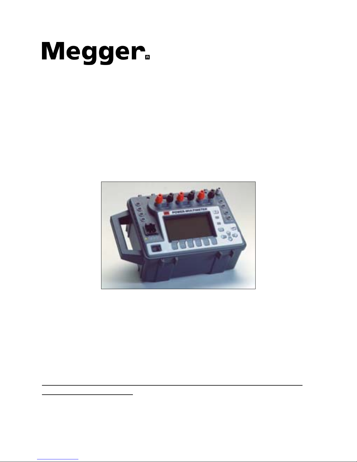
User
Manual
Model PMM-1
POWER MULTIMETER
It is essential that this instruction book be read thoroughly before putting
the equipment in service!
®
Part No. 17357
Rev. 14 Date 01/21/2011
Page 2

REVISIONS HISTORY
Revision ECN# Date
0 Initial Release 04/28/97
1 27562 06/27/97
2 28040 12/01/98
3 28510 06/17/99
4 11/29/99
5 28834 9/20/00
6 29040 08/06/01
7 29638 4/30/03
8 29650 5/14/03
9 29716 10/16/03
10 30270 02/28/06
11 31326 2/24/2010
12 31327 2/25/2010
13 31338 3/22/2010
14 31520 1/21/2011
IMPORTANT
The information and data contained within this instruction manual are proprietary with
Megger®. The equipm
ent described herein may be protected by one or more U.S.
letters patent. Megger specifically reserves to itself all rights to such proprietary
information as well as all rights under any such patent, none of which is waived by the
submission of this instruction manual to anyone.
The recipient, if a Government agency, acknowledges that this instruction book and the
equipm
ent described were procured with "Limited Rights" to technical data as described
in ASPR 9-203 (b).
⎯⎯⎯⎯⎯⎯
Copyright Megger 1997, 1998, 1999, 2000,2001, 2002, 2003, 2006, 2010
Page 3

TABLE OF CONTENTS
1OPERATOR SAFETY ..........................................................................................................1
1.1DESCRIPTION ...............................................................................................................1
1.2EXPLANATION OF SAFETY SYMBOLS .......................................................................1
1.3GROUNDING .................................................................................................................2
1.4POWER CORD AND FUSES .........................................................................................2
2GENERAL INFORMATION..................................................................................................3
2.1DESCRIPTION ...............................................................................................................3
2.2APPLICATIONS..............................................................................................................3
2.3FEATURES.....................................................................................................................3
2.4ELECTRICAL SPECIFICATIONS...................................................................................5
2.5SAFETY, MECHANICAL AND ENVIRONMENTAL SPECIFICATIONS .........................6
2.6ORDERING INFORMATION ..........................................................................................6
2.7CHANGES......................................................................................................................7
2.8WARRANTY ...................................................................................................................7
3INSTALLATION ...................................................................................................................8
3.1UNPACKING AND INSPECTION ...................................................................................8
3.2PREPARATION FOR USE .............................................................................................8
3.3REPACKING AND SHIPMENT.......................................................................................8
4OPERATING INSTRUCTIONS.............................................................................................9
4.1PANEL CONTROLS AND OPERATING FUNCTIONS...................................................9
4.2SAFETY CONSIDERATIONS.......................................................................................11
4.3USING THE INTERNAL BATTERY ..............................................................................11
4.4GENERAL OPERATING INSTRUCTIONS...................................................................13
4.5SINGLE PHASE OPERATION .....................................................................................13
4.5.1SELECTING THE INPUT CHANNEL......................................................................14
4.5.2THE MEASURING FUNCTIONS ............................................................................16
4.5.3THE MAX HOLD FEATURE ...................................................................................17
i
Page 4

4.6THREE-PHASE OPERATION ......................................................................................18
4.6.1SELECTING THE CONFIGURATION ....................................................................18
4.6.2THE MEASURING FUNCTIONS ............................................................................19
4.7CLAMP-ON CURRENT AND POTENTIAL TRANSFORMER OPERATION ................20
4.7.1MEASURING PRIMARY CURRENT ......................................................................20
4.7.2VERIFYING THE RATIOS OF CTS........................................................................21
4.8HIGH-SPEED SINGLE-PHASE CAPTURE MODE ......................................................23
4.8.1THE MEASURING FUNCTIONS ............................................................................24
4.9TIMER/RELAY OPERATION........................................................................................27
4.9.1MODES OF OPERATION.......................................................................................27
4.9.2THE MEASURING FUNCTIONS ............................................................................28
4.10VIEW SAVED DATA Directory...................................................................................29
4.11TIMED DATA TRANSMISSION.................................................................................30
4.12SETTING THE CLOCK AND DATE...........................................................................34
4.13PERIPHERAL OPERATION ......................................................................................34
4.13.1PRINTER PORT ..................................................................................................34
TABLE 4-1DOT MATRIX PRINTER PORT PIN-OUT .....................................................35
4.13.2RS232 SERIAL DATA PORT...............................................................................35
TABLE 4-2 RS232 CONNECTOR PIN-OUT ......................................................................36
POWER MULTIMETER COMMAND SET ..........................................................................37
CALIBRATION PROCEDURES..........................................................................................41
PMM-1 QUICK TIPS...........................................................................................................45
EXAMPLES ........................................................................................................................46
Power DB PROGRAM INSTRUCTIONS ............................................................................55
5SERVICE AND MAINTENANCE........................................................................................63
6ADDENDUM – USING PMM-1 FOR DELTA POWER MESAUREMENTS........................63
ii
Page 5

1 OPERATOR SAFETY
ATTENTION: READ THIS MANUAL BEFORE PROCEEDING WITH
INSTALLATION AND OPERATING THE INSTRUMENT.
1.1 DESCRIPTION
This instrument must be operated, used and serviced ONLY by trained, qualified
personnel. Misuse of electrical instruments can result in personal injury and
damage to the apparatus under test. Obey all applicable safety rules and
regulations at all times.
Refer to the following sections of this manual for operating specifications and
procedures.
1.2 EXPLANATION OF SAFETY SYMBOLS
Megger uses, where applicable, the following IEC 417 symbols on its
instruments:
This symbol indicates that the operator of the
instrument must refer to the instruction manual for
further explanation and clarification.
Safety Ground Terminal. This terminal must be
connected to an earth ground before making other
connections to the instrument and prior to operating
it!!!
This red symbol indicates that high voltage (i.e., any
voltage equal or greater than 1000 Volts) is present
on the terminal. Use extreme care.
This is the symbol for a sinusoidal AC voltage or
current.
AC or DC voltage.
1
Page 6
1.3 GROUNDING
Where a ground binding post or a grounding lead is provided on the instrument, it
must be connected to an earth ground PRIOR to making any other connections.
WARNING: To avoid electric shock do not interrupt the connection to the
protective safety ground.
1.4 POWER CORD AND FUSES
The power cord must be connected to a grounded supply system with proper
electrical ratings, as indicated on the instrument.
In the case of detachable power cords, only the cord supplied or specified by
Megger should be used.
WARNING: TO AVOID ELECTRIC SHOCK
ALWAYS DISCONNECT THE POWER CORD FROM
THE SUPPLY CIRCUIT BEFORE SERVICING THE
INSTRUMENT OR WHEN REPLACING A FUSE.
WARNING: ALL FUSES MUST BE REPLACED
WITH THE SAME TYPE AND CURRENT AND
VOLTAGE RATINGS. SHORT-CIRCUITING THE
FUSEHOLDER IS PROHIBITED.
2
Page 7

2 GENERAL INFORMATION
2.1 DESCRIPTION
The Megger POWER MULTIMETER (Model PMM-1) is a next generation
portable battery/line operated multifunction instrument for measuring AC or DC
voltage, AC primary and secondary current, power, reactive power, phase angle
and frequency of a single or three phase electrical system. POWER
MULTIMETER is easily configured to measure the amplitude and phase angle
between any two voltage and current inputs. All measured quantities are
displayed simultaneously on an easy-to-read graphic display.
The unique firmware in the POWER MULTIMETER, combined with a built-in
microprocessor-based timer, is specifically designed to ease testing and
commissioning of protective relay systems, including induction unit pick-up and
timing tests. The internal timer responds to a variety of start and stop gates,
including the application of AC or DC voltage, and opening or closing of dry
contacts.
POWER MULTIMETER is a menu driven instrument equipped with data-
retention and TIMED data-logging capabilities. Automatically stores measured
data at user defined intervals. Transmit them to a PC on a pre-programmed time
interval or save data directly to NOV RAM memory.
Other important features include accurate phase angle measurement at very low
current levels, max hold and the high speed measurement modes.
2.2 APPLICATIONS
POWER MULTIMETER is an ideal instrument for use in general electrical
systems maintenance, in electrical machine repairs, in protective relay testing, or
in monitoring power at the electrical service entrance.
In the protective relay application area, POWER MULTIMETER is designed to
perform fast, accurate checking and testing of protective relay and meter
installations, during their commissioning and in routine maintenance.
Also, combined with a source of voltage and/or current, POWER MULTIMETER
becomes an excellent tool for testing and calibrating various types of protective
relays.
2.3 FEATURES
• Battery and line operated, with an automatic built-in charger.
• Rugged, ergonomic and light plastic enclosure.
3
Page 8

•
3 independent voltage and current channels, with a built-in timer.
• Specifically designed to ease testing and commissioning of protective
relay systems.
•
Simultaneously measures and displays voltage, current, phase angle,
power, reactive power, power factor, and frequency of single or three
phase systems.
•
Wide current and voltage operating ranges.
• High speed measurement mode, with up to 1200 sets of readings in single
phase mode and up to 400 sets of readings in three phase mode.
•
Accurate phase angle measurement at very low current levels.
• Timer mode, phase angle between the voltage and current is measured
and displayed.
•
Auto-ranging to reduce test time, with manual over-ride.
• RS232 data and parallel printer output ports.
• Large, easy-to-read, high-resolution LCD display.
• Menu driven, easy to operate.
• Data storage for saving measured values.
• Programmable Time Data Logging to Memory.
• Customize C.T. ratio inputs up to a ratio of 9999:1 or 9999:5.
• Customize P.T. ratio inputs up to a ratio of 9999:1 or 9999:5.
• Megger Power DB Lite software to recover and print data.
• Harmonic measurement of any selected voltage or current – up to the 49
th
harmonic.
4
Page 9
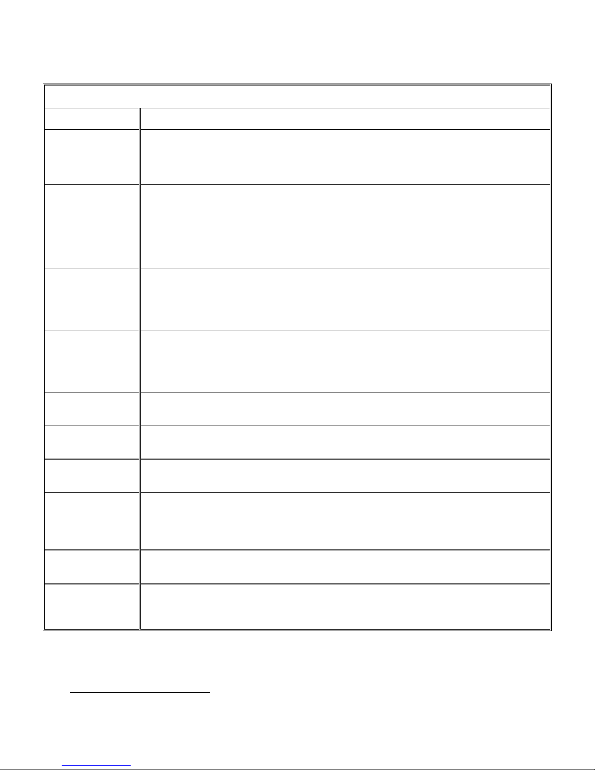
2.4 ELECTRICAL SPECIFICATIONS
∗
SPECIFICATIONS
Input:
Battery:
Voltage:
Current:
Phase Angle:
Power:
Reactive
Power:
Operating
Frequency:
Time:.
Start/Stop
Inputs:
Response
Time:
Line: 90-253 V, 50/60 Hz, 30 VA
Internal, sealed lead-acid, rechargeable battery with an internal automatic charger.
Safety features include Internal battery over-charging and charge exhaustion
protection.
Operation Time: 10-Hour continuous on full charge.
0 - 650 Volts (AC/DC) in 8 ranges, with 0.1% resolution.
Accuracy at 50/60 Hz: ±0.05% of reading, from 3-650 AC Volts. (21° - 25°C)
±0.1% of reading, from 3-650 AC Volts. (0° - 50°C)
±0.1% of reading, from 3-650 DC Volts.
Input impedance: 1 MΩ.
Max input: 1000 Volts, from inputs to the chassis or between inputs.
0 - 100 Amperes (AC) in 10 ranges, with 0.1% resolution.
Accuracy at 50/60 Hz: ±0.05% of reading, from 0.10-10 Amperes (21° - 25°C).
±0.1% of reading > 10 amperes.
Burden at 5A: 0.1VA.
± 0 - 180.0° and 0 - 360° lead or lag, with 0.01° resolution.
Accuracy at 50/60 Hz: ±0.05° for input levels above 30 Volts and 1 Amps
1
, ±0.5°
for input levels above 3 Volts and 0.02 Amps
± 2° input levels below 3 Volts and 0.02 Amps.
± 0 - 100 KW, with 0.1% resolution.
Accuracy at 50/60 Hz: ±0.1% of VA.
± 0 - 100 KVAR with 0.1% resolution.
Accuracy at 50/60 Hz: ±0.1% of VA.
45 - 65 Hz, with 0.01 Hz resolution.
Accuracy: ± 0.03 Hz.
0.000 to 999.999 Seconds. Accuracy: ±0.005% of reading or LSD whichever is
greater.
0.000 to 9999.9 Cycles. Accuracy: ±0.5 Cycle when initiated by dry contact or
potential above 5 Volts DC or 115 Volts AC.
5 - 300 Volts AC, DC, or dry contacts closure or opening.
Input resistance: 1000 Ω Minimum.
Regular single-phase mode: 1 reading per second
High Speed Mode: 20 readings per second/60 seconds max.
Three-phase mode: 1 set of readings every second.
∗
Specifications subject to change.
1
When using current as reference, using voltage as reference the accuracy changes to ±0.1°
5
Page 10

2.5 SAFETY, MECHANICAL AND ENVIRONMENTAL SPECIFICATIONS
Safety:
IEC 61010-1, Overvoltage CAT II
Case Material:
Dimensions: 344W x 242H x 242D millimetres
(13.5W x 9H x 9D inches)
Weight: 6.0 Kg (13.4 Lbs), approximately
Operating Temperature: -15°C to 55°C (5°F to 131°F)
Storage Temperature: -30°C to 75°C (-22°F to 167°F)
Relative Humidity: 10 to 95%, NON-CONDENSING
2.6 ORDERING INFORMATION
Cat. No.
POWER MULTIMETER PMM-1
The instrument is shipped complete with:
Line cord, three wire, 120V 6828
Instruction Manual 17357
(2) Fuses 1.0 A 250 V, 5 x 20 mm MC7797
Accessory Pouch External Mount Portable Case 17355
PMM1- Power DBLite software DB0001
The following optional accessories are available:
Standard Potential Leads [set of 4, 2m] 835312
Fused Potential Leads [set of 4, 2m] 830213
20-Amps Current Leads, States Plugs [set of 3, 1m] 835313
20-Amp Current Leads, clips [set of 3, 1m] 835314
100-Amp Current Leads [set of 3, 1m] 835315
1000:1 Clamp-On Current Transformer 830312
1000:5 Clamp-On Current Transformer 835318
3000:1 Clamp-On Current Transformer 835319
3000:5 Clamp-On Current Transformer 835320
200:1 Minature Clamp-On Current Transformer 50611
Soft Carrying Case 50775
6
Page 11

2.7 CHANGES
Please note that this instrument is subject to continuous development and
improvement. This instrument may therefore incorporate minor changes in detail
from the information contained herein.
2.8 WARRANTY
Megger warrants the equipment, sold by us or our authorized agents, to be free
from defects in material and workmanship, reasonable wear and tear excluded,
for a period of 12 months from date of shipment.
Warranty service will be performed on the equipment at the Megger factory
(unless the return of only a subassembly is authorized by Megger) or, at
Megger's discretion, in the field. The cu
stomer shall prepay shipping charges for
units returned to Megger, and Megger shall pay for the return of the required or
replaced unit to the customer, repair or replace (at Megger's option) the unit or
subassembly provided that the Instrument has not been altered, modified or
repaired by unauthorized personnel, and that our examination discloses to our
satisfaction that any improper operation or failure was not the result of improper
use, negligence or accident, exceeding environmental limits, or connecting the
Instrument to incompatible equipment. The customer is asked to obtain return
authorization from Megger PRIOR TO returning a unit for service.
This warranty covers the cost of repairing or replacing faulty components at
Megger's option, but not the cost of travel and living expenses of service
personnel for work completed in the field. Any field service trips will be subject to
inspection of the Megger service representative. If it is determined upon arrival
that the repair is not covered by the Warranty, the customer must be prepared to
cover the standard rates of the Megger service representative(s) in addition to
the cost of travel and living expenses of the service personnel. The invoice for
the full amount of the non-warranty repair will be submitted by the Megger office
upon the return of the service representative. The customer must remit the
required payment immediately fo
r all service work performed.
Products manufactured by Megger to customer's specifications are warranted to
be free from defects in material and workmanship and to conform to those
specifications made a part of Megger's quotation, or of a customer's Contract or
Purchase Order. Inspection and acceptance shall be conclusive as to fulfilling
this warranty, except as to fraud or such gross mistakes as to amount to fraud.
Since Megger has no control over conditions of use, no warranty is made or
implied as to suitability for customer's intended use beyond such performance
specifications as are made a part of Megger's quotation, or of a customer's
contract or purchase order which has been approved and acknowledged by
Megger. No other warranty is either expressed or implied. Megger shall not be
liable for consequential damages.
7
Page 12

3 INSTALLATION
3.1 UNPACKING AND INSPECTION
Prior to shipment this instrument was electrically tested and mechanically
inspected to meet specifications
and be free of mechanical defects.
After unpacking the instrument, visually inspect the instrument and accessories
for damage. If evidence of damage is present, YOU
must contact the carrier who
transported the unit and file a claim in writing. The shipping container and
packing material should be retained for inspection by the carrier's agent.
Electrical operation per section 4 should be checked as soon as possible after
shipment.
3.2 PREPARATION FOR USE
THIS INSTRUMENT IS DESIGNED TO BE USED TO MEASURE
POTENTIALLY LETHAL VOLTAGE AND CURRENT. It is highly recommended
that the user familiarize himself with the controls, functions and features detailed
in section 4 prior to use. ALL SAFETY PROCEDURES AND PRECAUTIONS
MUST BE FOLLOWED WHEN OPERATING ON LINE WITH LETHAL
VOLTAGES OF HIGH CAPACITY!!!
3.3 REPACKING AND SHIPMENT
To insure proper shipment of this instrument, it is recommended that the original
reusable container and packing material be retained. If being returned for
calibration or service, please attach a card to the instrument specifying the
owner, model and serial number and service required.
8
Page 13

4 OPERATING INSTRUCTIONS
4.1 PANEL CONTROLS AND OPERATING FUNCTIONS
Refer to FIGURE 4-1. for the following panel controls.
1. LINE INPUT SOCKET: This is the main input for the POWER
MULTIMETER, and should be connected to a suitable line receptacle,
using the provided line cord. The input socket also contains the protection
fuse. Replace with type GDC, 1 Amp, 250 Volts only.
2. MAIN POWER SWITCH: Bring the switch to the right position to activate
the instrument.
3. AC LINE INDICATOR: This LED will illuminate when the input plug is
connected to a live line power.
4. BATTERY CHARGED INDICATOR: This LED will illuminate when the
internal battery is charging to its full capacity or has degraded to 20% of its
full capacity.
5. PROTECTIVE GROUND TERMINAL: The safety protective chassis
ground connection for the instrument. This terminal is internally
connected to the U ground.
NOTE: The protective ground terminal must be connected to an earth
ground before making other connections to the instrument and prior to
operating it!!!
6. DISPLAY: The display is a high-resolution graphic LCD.
7. FUNCTION KEYS: These pushbuttons are operated in conjunction with
the display. The display provides indication of key function. Function of
each key varies with each screen.
8. MENU KEY: When depressed, the POWER MULTIMETER will return to
the Main Menu.
9. LEFT/RIGHT CURSOR KEYS:
The cursor keys allow the operator to
move, in the left and right directions, to different fields on the screen.
10. UP/DOWN CURSOR KEYS: The cursor keys allow the operator to move,
in the up and down directions, to different fields on the screen.
9
Page 14
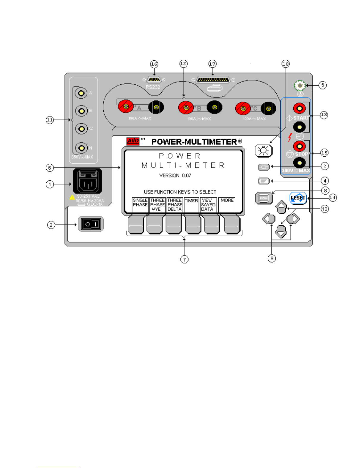
FIGURE 4-1 FRONT PANEL OF THE POWER MULTIMETER
11. VOLTAGE INPUTS: The single or polyphase voltages are connected to
these binding posts, as labelled.
12. CURRENT INPUTS:
Three independent current circuits may be
connected to these binding posts. The correct polarity, for the phase
angle measurement purposes, is indicated by the red terminal and a grey
dot.
13. START INPUTS: Interval timer start binding post connections.
14. RESET KEY:
This key is used to reset the meter in certain measuring
screens.
15. STOP INPUTS: Interval timer stop binding post connections.
16. RS232 OUTPUT PORT:
This port is provided for transmitting and
receiving the data results to and from an external PC or a data terminal.
17. PARALLEL PRINTER PORT: The printer port can be connected to a Dot
Matrix compatible parallel printer, for printing the test results.
10
Page 15

18. DISPLAY BACK-LIGHT SWITCH: This switch controls the display back-
light. In low ambient light conditions, the back-light allows the operator to
see the display. If not needed, the back-light should be turned off to
preserve the battery.
4.2 SAFETY CONSIDERATIONS
The measuring terminals of this instrument can be connected to lethal voltages
and hazardous current circuits. Professional organizations using this instrument
will normally have safety procedures covering such installations and users will be
trained to follow them. Not withstanding these conditions, certain precautions
should be followed when using this instrument.
1. The chassis ground connection should always be firmly attached to the
system ground bus, even when an AC line cord is used.
2. Connections should be established to the potential and current terminals
before the measuring circuit is energized.
3. The use of potential leads containing high rupture fuses is recommended
in high KVA circuits.
4. All current terminals should be tightly fastened, to avoid dangerous
terminal voltages and preclude ohmic heating at high currents.
4.3 USING THE INTERNAL BATTERY
NOTE: If the PMM-1 has been in transient for more than a week, it is very
important that the unit be given a full charge before being used in the
battery operation mode.
The internal charger will automatically charge the battery when the line power is
applied to the instrument. When the battery is charging, the `battery charged'
LED illuminates. The instrument can be used while the battery is being charged.
The BATTERY Charge LED also acts as low-battery indicator. This LED will
flash at a constant rate, once the battery charge drops below 25%.
11
Page 16

In order to prolong the life of the battery and ensure optimum performance, the
following procedure should be observed:
1. Charge the battery overnight after using the instrument for a short time or
after a whole day.
2. Charge the instrument at least once a month, if it is stored unused, store it
connected to a power line.
3. If the battery condition has been allowed to deteriorate due to lack of
attention, charge it for a period of up to 12 hours to allow the charger to
recover the condition of the battery.
12
Page 17

4.4 GENERAL OPERATING INSTRUCTIONS
The following is a general procedure for operating the POWER MULTIMETER.
1. NOTE: Due to the sensitivity of the Power Multimeter to very low levels of
voltage and current, it is highly recommended that the protective ground
terminal be connected to an earth ground and jumpered to the voltage
input neutral post before making any measurements!!! This is
recommended even if the AC power cord is used.
2. If the AC power is used, connect the provided AC power cord to a suitable
supply. The POWER MULTIMETER is equipped with a wide input range
power supply and therefore can be operated from 90 to 253 Volts (AC), 50
or 60 Hertz.
3. Turn on the instrument by toggling the power switch to its ON - position.
The instrument should display the Main Menu.
NOTE: To adjust the screen contrast, press the MORE function key
and use the LESS or MORE contrast function keys to set the screen
contrast.
4. The Power Multimeter is shipped with default settings. Timer Horn:
Disabled, measuring mode: 60 Hz, and Phase Angles: 0 - 360° Lag. To
make changes to the settings, press the More function key, then select
SetUp Page2. In the SetUp Page2 screen complete the desired changes,
then press the OK or Menu key to initialize the changes.
Note: The unit saves the selections/changes made in the SetUp Page2
screen. Turning the unit OFF and ON will not restore the default settings.
5. Make the proper connections to the voltage and/or current channel inputs.
Connections should be established to the potential and current terminals
before the measuring circuit is energized!!!
6. Proceed with the actual test as described in the following sections.
4.5 SINGLE-PHASE OPERATION
The single-phase operation mode is intended for measuring a single voltage and
current, two voltages or two currents. This mode features a quick input selection
menu, which enables the operator to measure various quantities in a single- or
poly-phase installation.
Note: Lag ; displayed phase angles lags the reference in the Lag mode. Lead
;
displayed phase angles leads the reference in the Lead mode.
13
Page 18
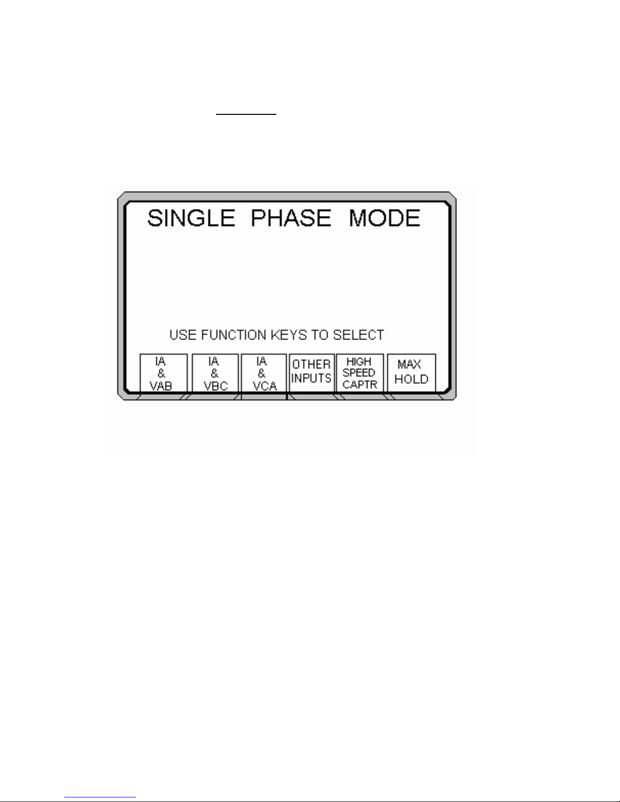
4.5.1 SELECTING THE INPUT CHANNELS
1. From the Main Menu, press the SINGLE PHASE function key. The
following should appear on the display.
2. From the single-phase screen, select the input channels required. The
following quick selections are provided for convenience:
-
-
-
Ia & Vab For one-current and two voltage
measurements. The current is applied to A
current terminals, and the voltage is applied
between the A and B voltage terminals.
Ia & Vbc For one current and two voltage
measurements. The current is applied to A
current terminals, and the voltage is applied
between the B and C voltage terminals.
Ia & Vca For one current and two voltage
measurements. The current is applied to A
current terminals, and the voltage is applied
between the C and A voltage terminals.
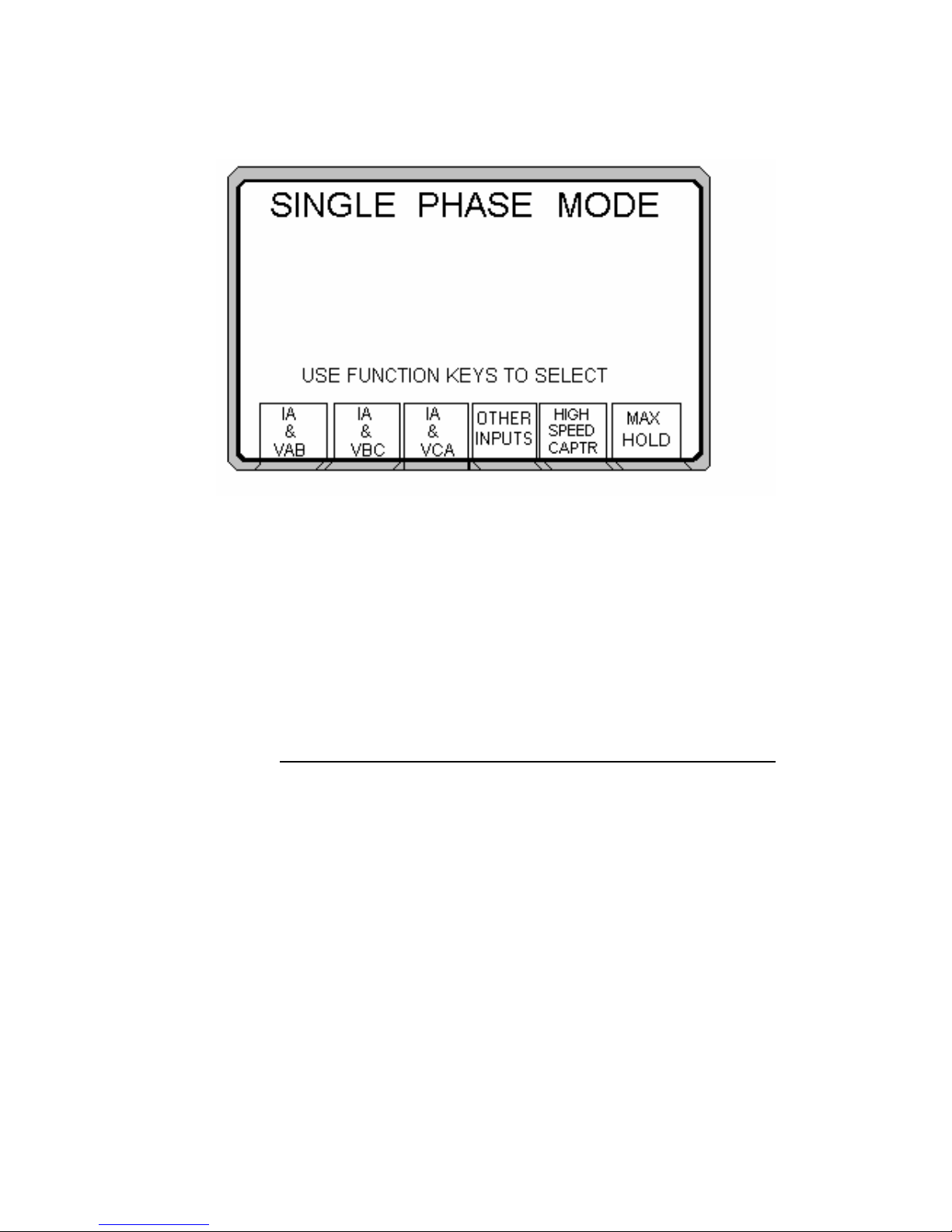
Press the corresponding function key to activate the measurement on any
of the above selections. Pressing OTHER INPUTS results in the following,
14
Page 19
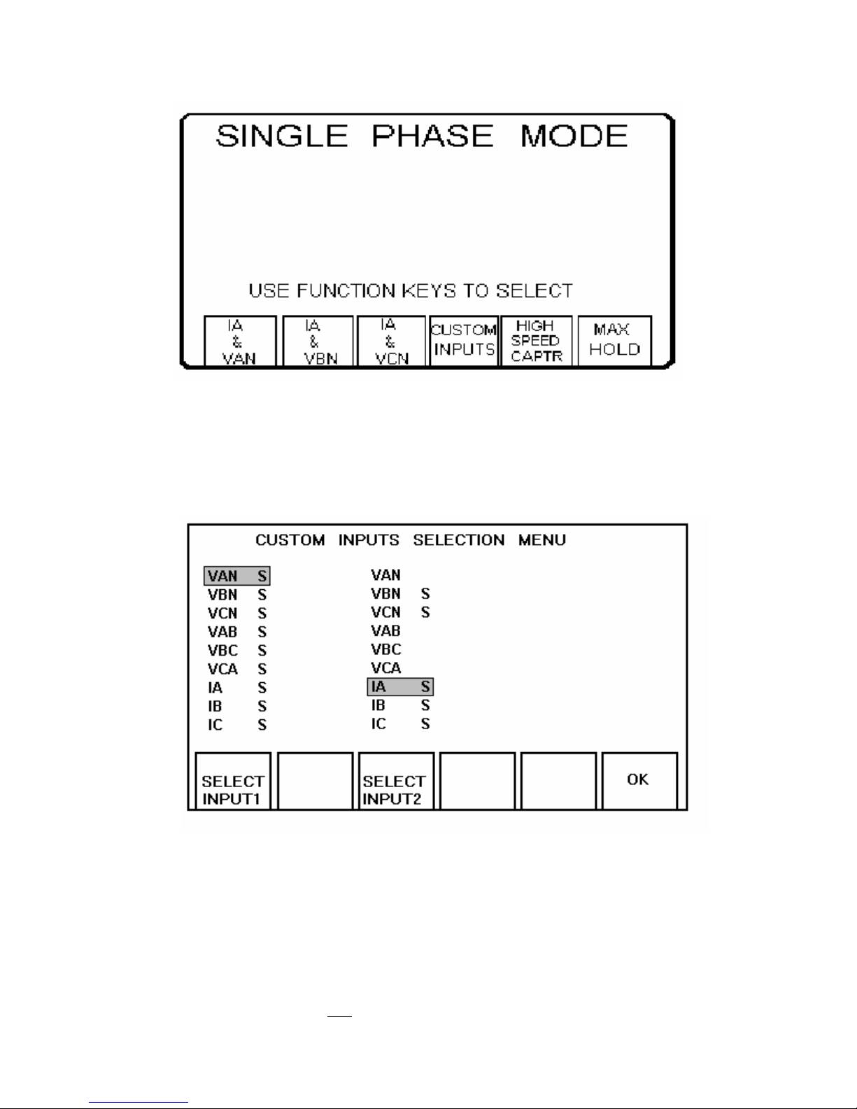
If inputs other than the ones listed above are required, press the CUSTOM INPUTS
function key. The instrument will display the following:
3. Use the SELECT INPUT 1 and SELECT INPUT 2 function keys to
configure the measurements. Note that certain combinations of
input 1 and 2 are not possible. The instrument automatically
disables these combinations.
4. Press the OK function key to activate the measurement.
15
Page 20
4.5.2 THE MEASURING FUNCTIONS
1. Anytime during the course of measurement, the serial and/or
parallel (i.e., printer) transmission can be activated.
In order to activate the transmission, make the appropriate
connection to the PRINTER or RS232 device. Refer to section
4.13. for more details.
Press the PRINT function key to initiate the transmission. If the
instrument establishes proper communication with the external
device (i.e., printer), DATA will be printed.
Improper communication will prompt an error message!
2. If the timed data transmission has been activated, measured data
will be sent to the external device at the set time interval. Please
refer to section 4.11. for information on timed data transmission.
3. The START or STOP inputs respond to a change of state. This
change may be a dry contact opening or closure, or the initial
application/removal of an AC or DC voltage. The input terminals
are isolated from the chassis ground and are independent of signal
polarity.
4. To save the measurements, simply press the SAVE function key.
Pressing this key will TAG NUMBER the sub-screen. This number
is tagged to the saved data, for future reference. All saved data are
time and date stamped.
16
Page 21
5. The instrument automatically defaults to true RMS measurement.
To change the measurement mode to AVERAGE, press the Volt
function key to toggle from RMS to AVG.
NOTE:
When measuring DC volts, the instrument must be in
the RMS
measurement mode only and positive
polarity connected to VA, VB, or VC!
6. The instrument defaults to automatic ranging. If manual ranging is
desired, the unit must be in High Speed Capture or Timer Mode.
Proceed as follows:
- Press HIGH SPEED CAPR function key. Select the
CHANGE I & V RANGE function key.
- Press CHANGE I RNG to set the current range desired.
- Press CHANGE V RNG to set voltage range desired, after
making the changes, press OK to enter the new
configuration.
Please refer to section 4.7 if an external clamp-on current transformer is
used.
7. Press the ESC function key, to return to the Single-Phase input
selection screen.
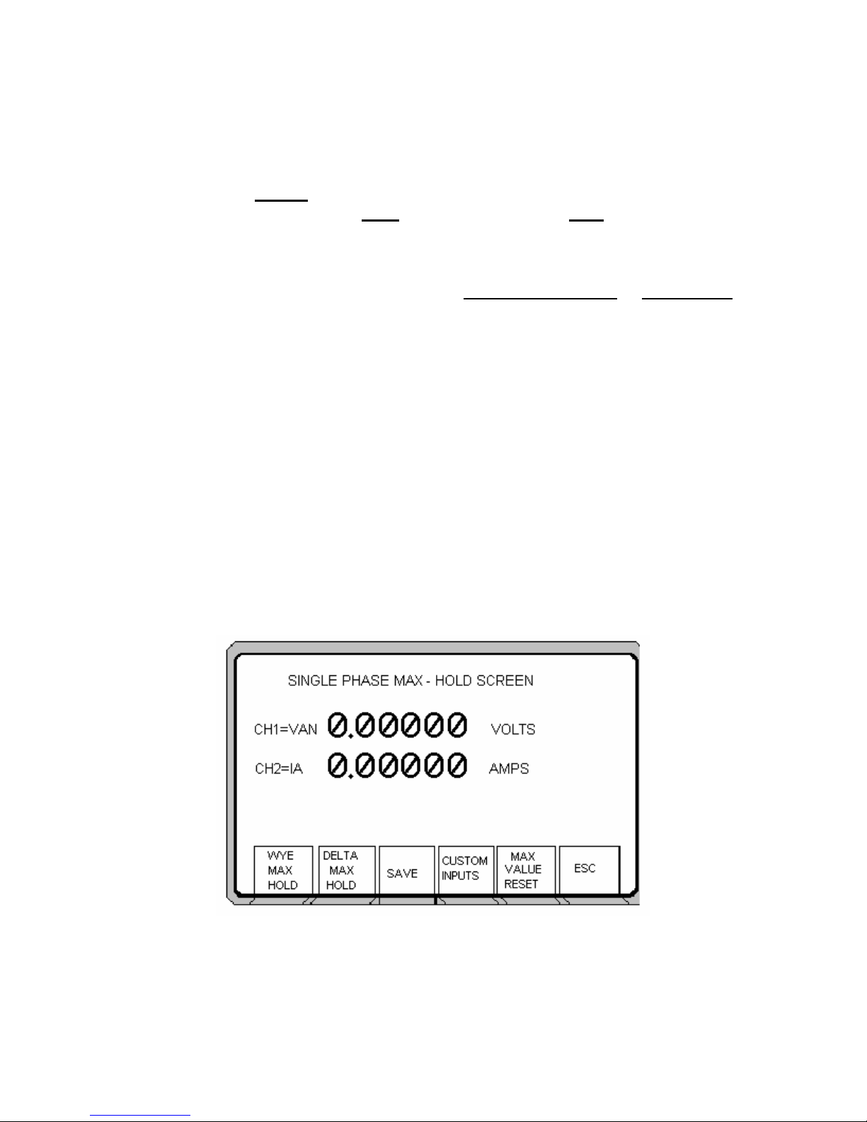
4.5.3 THE MAX HOLD FEATURE
Pressing the MAX HOLD button in the Single-Phase Mode will result in the
display of the selected single phase measuring screen. The PMM-1 will
continuously monitor the selected inputs, and will display the highest value
metered during the monitored period of time. It should be noted that the
highest value must be present for at least 1 second, and only the highest
value will be displayed. To save the value press SAVE, see section 4.10 to
17
Page 22
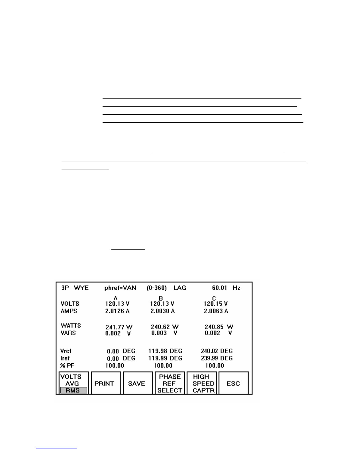
VIEW SAVED DATA. Pressing WYE MAX HOLD or DELTA MAX HOLD
will display the desired three-phase MAX HOLD screen. The same singlephase feature applies to the three phase MAX HOLD function.
4.6 THREE-PHASE OPERATION
NOTE: Due to the sensitivity of the Power Multimeter to very low levels of
voltage and current, it is highly recommended that the protective
ground terminal be connected to an earth ground and jumpered to
the voltage input neutral post before making any measurements!!!!
This is recommended even if the AC power cord is used.
The three-phase operation mode is intended for measuring all 3-phase quantities
in a wye or delta installation. Note: Lag ; displayed phase angles lags the
reference in the Lag mode. Lead ;displayed phase angles leads the reference in
the Lead mode.
NOTE: Instrument defaults to VAN as the phase reference. If current
only is to be measured, the phase reference must be changed to
IA, IB or IC.
Three phase watts are displayed in the three watt method.
4.6.1 SELECTING THE CONFIGURATION
From the Main Menu, select the THREE PHASE WYE or THREE PHASE
DELTA configuration by pressing the corresponding function key. The
instrument will immediately go into the measuring screen.
18
Page 23

4.6.2 THE MEASURING FUNCTIONS
1. Anytime during the course of measurement, the serial and/or
parallel (i.e., printer) transmission can be activated.
In order to activate the transmission, make the appropriate
connection to the PRINTER or RS232 device. Refer to section
4.13. for more details.
Press the PRINT function key to initiate the transmission. If the
instrument establishes proper communication with the external
device (i.e., printer), DATA
will be printed.
Improper communication will prompt an error message!
2. If the timed data transmission has been activated, measured data
will be sent to the external device at the set time interval. Please
refer to section 4.11 for information on timed data transmission.
3. The START or STOP inputs respond to a change of state. This
change may be a dry contact opening or closure, or the initial
application of an AC or DC voltage. The input terminals are
isolated from the chassis ground and are independent of signal
polarity.
4. To save the measurements press the SAVE function key.
Pressing this key will TAG NUMBER the sub-screen. This number
is tagged to the saved data, for future reference. All saved data are
time and date stamped.
5. The instrument automatically defaults to true RMS measurement.
To change the measurement mode to AVERAGE, press the Volt
function key to toggle from
RMS to AVG.
NOTE
: When measuring DC volts, the instrument must be in
the RMS
polarity connected to V
measurement mode only and positive
, VB, or VC!
A
6. The instrument defaults to automatic ranging. If manual ranging is
desired, the unit must be in High Speed Capture or Timer mode.
Proceed as follows:
- Press HIGH SPEED CAPR function key. Press the
CHANGE I & V RANGE
function key.
- Press CHANGE I RNG to select the current range.
- Press CHANGE V RNG to select the voltage range.
19
Page 24

- After making the changes, press the OK key.
Please refer to section 4.7 if an external clamp-on current
transformer is used.
7. Pressing ESC function key, will return the user to the three-phase
measurement screen.
8. Phase A voltage input is taken as the reference for phase angle
measurement. The operator may change the reference to either
VAN, VBN, VCN, IA, IB or IC, by pressing the Select Phase Ref
function key.
4.7 CLAMP-ON CURRENT AND POTENTIAL TRANSFORMER OPERATION
For application requiring direct measurement of primary current, five different
optional clamp-on current transformers ratios are pre-set with this instrument.
These ratios are 1000:1, 1000:5, 3000:1, 3000:5 and 200:1. If the clamp-on
being used does not match any of the pre-set options, simply move the cursor to
the Customize CT or PT.
There are two manners in which the clamp-ons can be utilized:
1. Measuring Primary current, watts and vars in a single- or three-phase
installation.
2. Verifying the ratios of CTs, used in relaying and metering installations.
The following sections detail the operation for each of these applications.
4.7.1 MEASURING PRIMARY CURRENT
1. For this application, connect the clamp-on CT(s) directly to the
current channel terminals on the front panel. Up to three clamp-ons
can used for three-phase applications. Note that the CTs are only
rated for 600 Volts class circuits.
2. To select the clamp-on ratio desired, proceed as follows:
20
Page 25
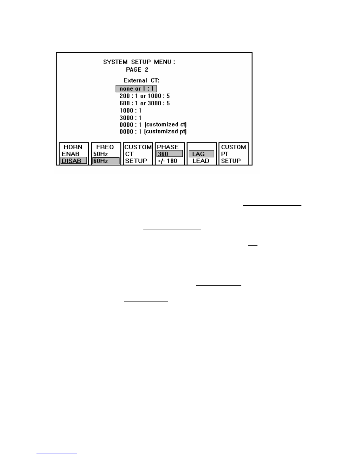
- From the Main Menu, press the More function key.
- From the More screen, press the SetUp Page2 function key.
-
-
From the SetUp Menu screen, press the ⇑ or ⇓ Arrow keys
to cursor to the preset CT ratios or the Customized Option
Preset ratioes are: None or 1:1, 1000:5 (200-1), 3000-5
.
(600-1), 1000:1, 3000:1, Customized, CT and PT.
- In the Customized SetUp
screen, the user can enter any
ratio up to 9999:1 or 9999:5.
- Once the selection is entered, press the OK function key to
return to the previous screen.
- Make the proper CT clamp connections to the unit and select
the type of measurement (Single or Three Phase) desired.
-
The Power MultiMeter will measure the current or currents
by the selected ratio or CUSTOMIZED CT or PT ratio.
-
After completion of the CT clamp on measurements, it is
recommended
that the unit be returned to its default setting:
(None or 1:1).
- Return to the CT ratio screen by following the same steps as
previously described or simply turn OFF the Power
Multimeter.
3. All measuring functions are explained in sections 4.5. and 4.6.
4.7.2 VERIFYING THE RATIOS OF CTS
1. For this application, connect the clamp-on CT directly to the phase
A current channel terminals on the front panel. Connect the
secondary of the CT under test to the phase B current channel
terminals.
21
Page 26
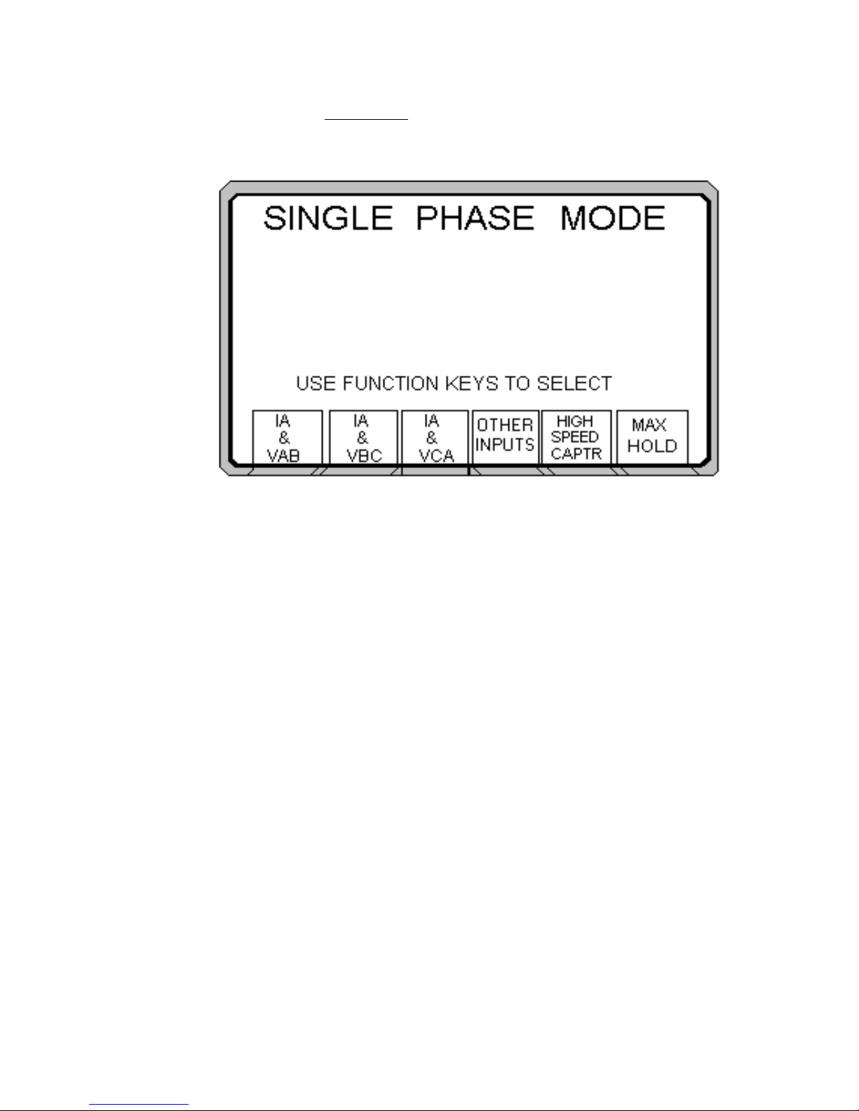
2. From the Main Menu, press the SINGLE-PHASE function key. The
following should appear on the display.
3. From the single-phase screen, select IA & VAB, by pressing the
corresponding function key. The measurement will be activated.
22
Page 27
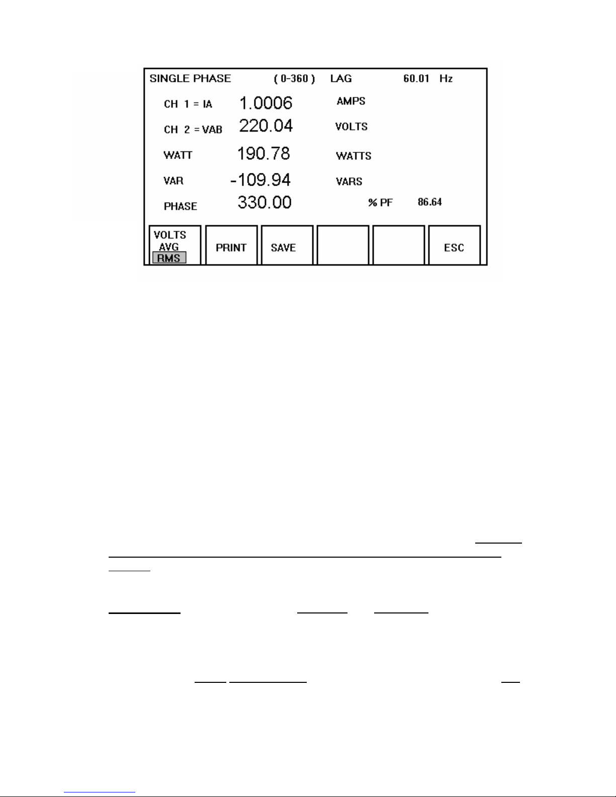
4. The instrument will default to automatic ranging. To change the
measuring ranges proceed as follows:
- Press ESC function key. The SINGLE PHASE MODE will
be recalled.
- Select HIGH SPEED CAPTR or go to TIMER MODE and
follow the same procedures as previously described in the
manual.
5. All measuring functions are as explained in sections 4.5.2.
4.8 HIGH-SPEED SINGLE-PHASE CAPTURE MODE
In the normal single-phase operating mode the instrument updates the readings
twice every second. For applications requiring faster update rate, such as
measuring currents and voltages of short duration, a high-speed capture mode is
available. In this mode the update speed is 20 times every second. The high
speed mode of operation works in conjunction with the START and STOP
circuitry, allowing the user to capture up to a maximum 60 seconds of test
results, in a controlled manner.
IMPORTANT
Default ranges are 750 Volts and 100 Amps. This mode allows
the user to select and set the voltage and current ranges before
initalizing the measurement test. All ranges have a +20% of the
selected range, if the amplitude exceeds the +20%, then it must
be noted that the resultant values will be considerably off. It is
highly recommended that the ranges selected be at least two
ranges above the expected amplitude or simply just leave it in
the defaulted ranges.
23
Page 28
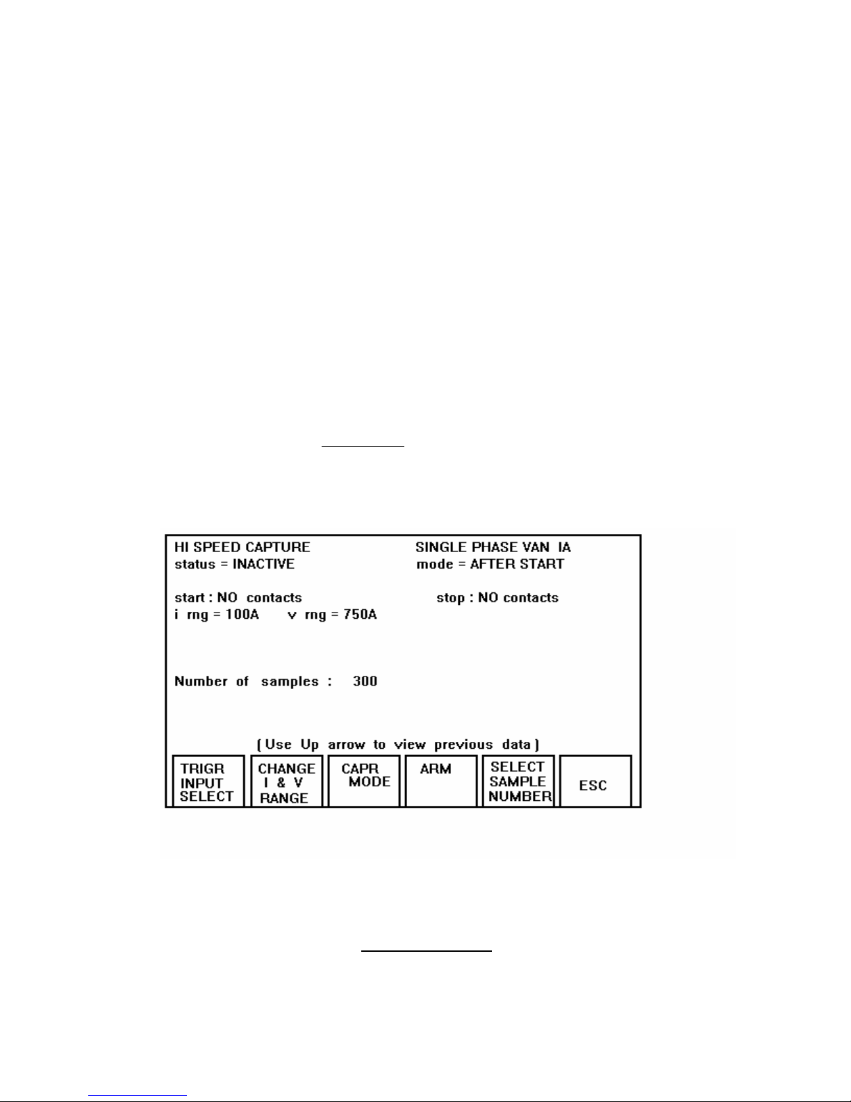
1. CAPTURE MODES: Two capture modes are available:
- AFTER-START: in this mode a maximum of 60 seconds/1200
samples of data can be captured after the measurement is initiated.
Use the START inputs to initiate the measurement. The
measurement will automatically abort 60-seconds after it is started.
Other measurement options are: 15 seconds/300 samples and 30
seconds/600 samples.
- NOTE: Stop inputs can be used to terminate measurement.
- BEFORE-STOP: in this mode a maximum of 60 seconds of data
can be capture. Use the start inputs to initiate the measurement
and the STOP inputs are used to terminate the test.
4.8.1 THE MEASURING FUNCTIONS
1. From the Main Menu
, press the SINGLE-PHASE function key.
2. Select HIGH SPEED CAPTR from the Single Phase screen. The
following will appear:
Note that the information on top of the screen indicates the default
conditions for this mode.
3. To change the TRIGGER INPUT press the TRIGR INPUT SELECT
function key. The following display will appear:
24
Page 29
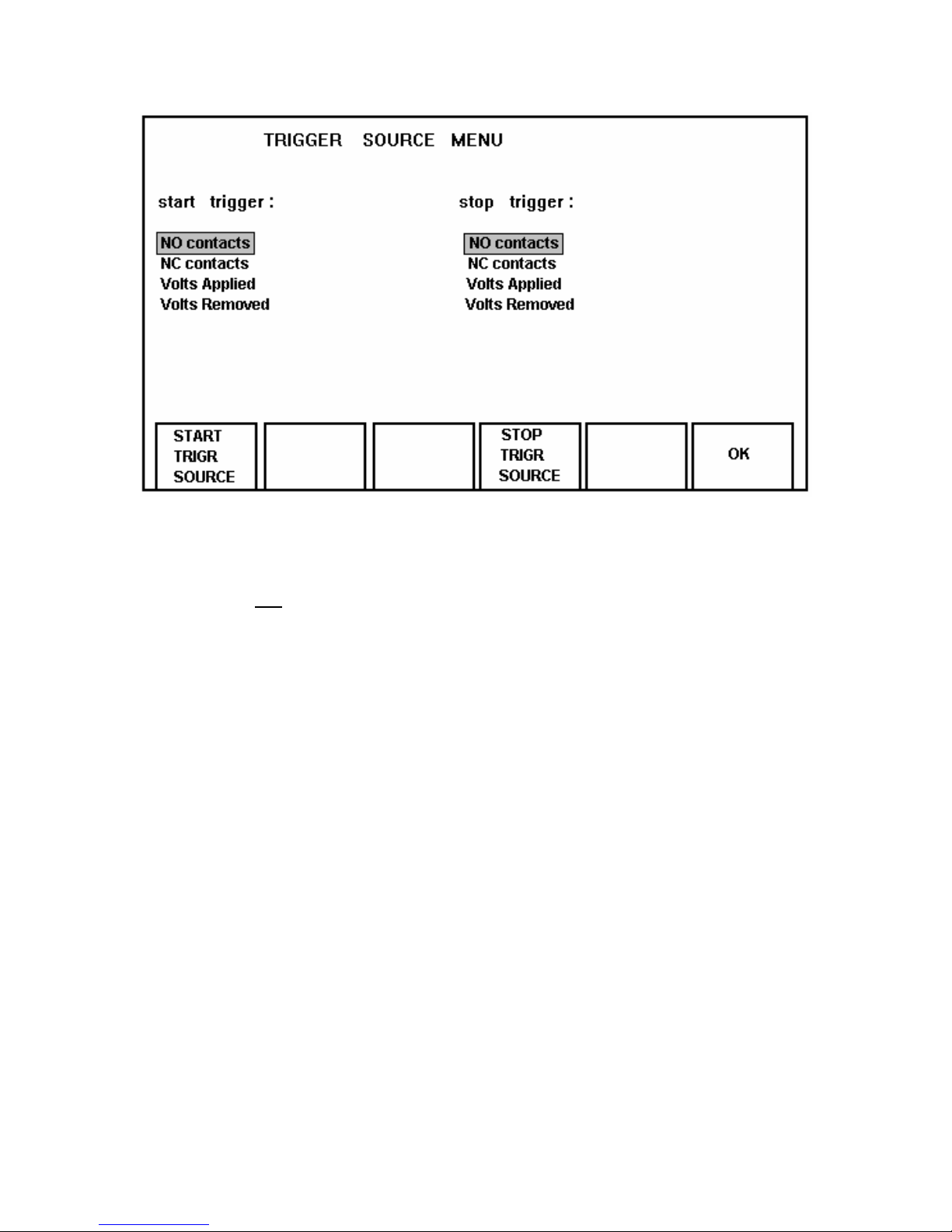
Press the START and STOP TRIGR function keys to highlight and select
the configuration desired.
To enter the new configuration and return to the previous screen, press
the OK
function key.
4. Pressing the CAPTR MODE function key will change the capture
mode from AFTER-START to BEFORE-STOP and vice versa, as
previously explained. Note the capture mode is shown on the top
right hand corner of the display.
5. Manual ranging is also available in this mode of operation. To set
the desired voltage and current range prior to the measurement.
Press the CHANGE I and V RANGE function key, and the following
screen will appear.
25
Page 30
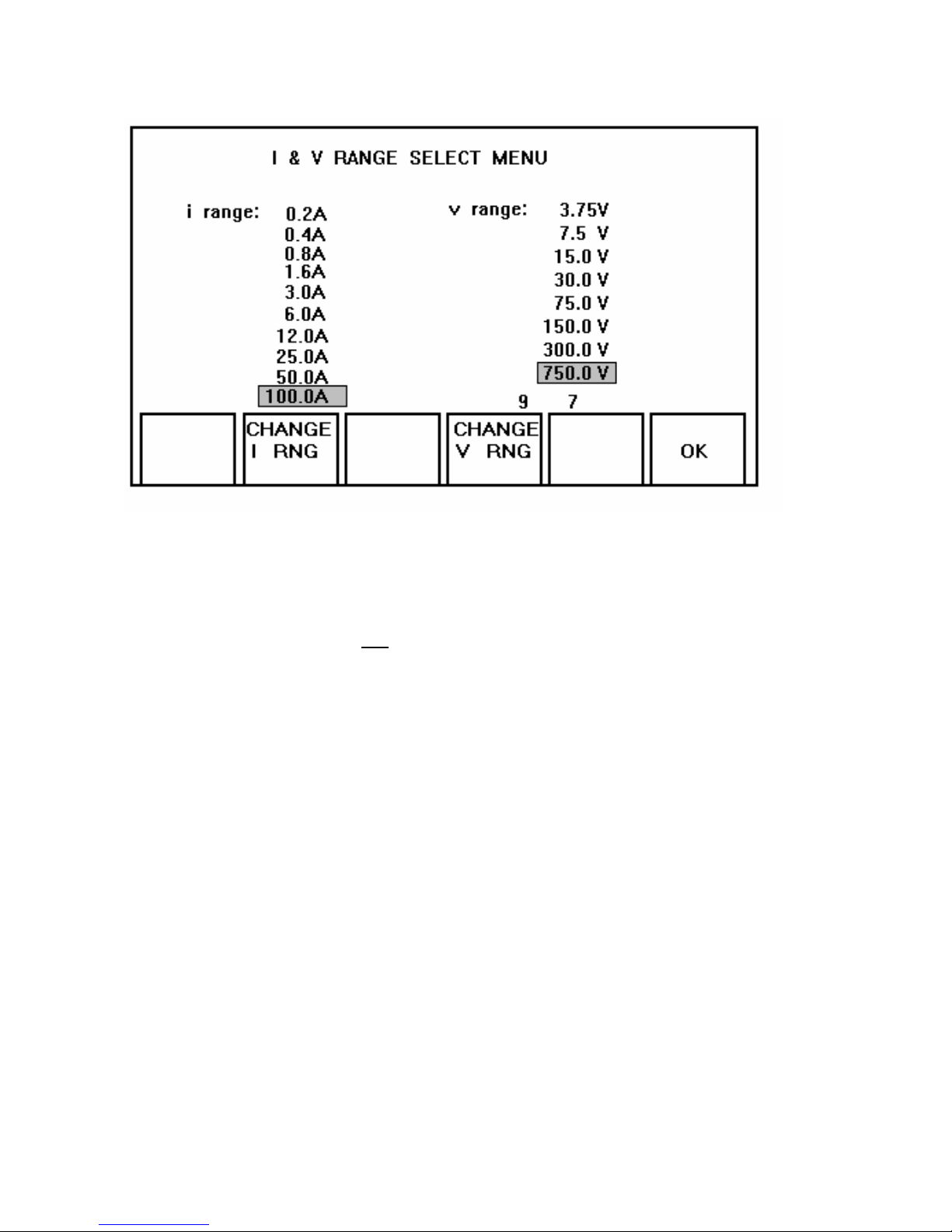
- Select CHANGE I & V RANGE.
- Press CHANGE I RNG to set the current range desired.
- Press CHANGE V RNG to set the voltage range desired.
6. To enter the new configuration and return to the previous screen,
press the OK
function key.
7. Once all the connections to the instrument are made, press the
ARM function key to arm the capture circuitry.
NOTE: Status will change from INACTIVE to ARM.
8. Use the START inputs to initiate the test. If a BEFORE STOP
mode of operation is selected, a STOP signal is required to
terminate the test. In a AFTER-START mode, the test is
automatically terminated depending on selection: 15, 30 or 60
seconds after it is started (15 sec/300 samples, 30 sec/600
samples or 60 sec/1200 samples).
The START or STOP inputs respond to a change of state. This
change may be a dry contact opening or closure, initial application
of an AC or DC voltage and . The input terminals are isolated from
the chassis ground and are independent of signal polarity.
9. Once the measurement is completed and data has been captured,
the data is automatically displayed. Use the PAGE UP or PAGE
DOWN function keys to scroll through the pages of data. The total
samples of readings and number of pages is dependent on
selection; 15 sec/300 samples, 30 sec/600 samples or 60 sec/1200
samples.
26
Page 31

10. In order to activate the transmission of the captured data to an
external printer or PC, make the appropriate connection to the
PRINTER and RS232 terminals. Refer to section 4.13. for more
details.
Press the PRINT function key to initiate the transmission. All pages
of captured data will be transmitted.
11. To save the data press the SAVE function key.
Pressing this key will TAG NUMBER the sub-screen. This number
is tagged to the saved data, for future reference. All saved data are
time and date stamped.
12. Press ESC to return to the previous screen.
4.9 TIMER/RELAY OPERATION
The POWER MULTIMETER is equipped with an internal timer, primarily intended
for performing timing tests on protective relays and circuit breakers. The timer is
equipped with a sensing circuitry that responds to a change of state. This
change may be a contact opening or closing, or the initial application of an AC or
DC voltage, or removal of an AC or DC voltage. The input terminals are isolated
from the chassis ground and are independent of signal polarity.
NOTE: When using the Timer posts in parallel with another test set, it is
very important that polarity be observed (red and black binding
post). If the binding posts are cross connected the timer will not
function correctly.
4.9.1 MODES OF OPERATION
There are two independent modes built into the TIMER/RELAY operation:
1. METER MODE: In this mode the timer is disabled, but the
voltmeter and ammeter are operating continuously. This mode of
operation, in conjunction with the STOP terminals, can be used to
verify minimum pick-up on protective relays. Note that the STOP
inputs act as a continuity detector in this mode.
2. TIMER MODE: In this mode the timer is armed and triggered using
the START inputs. The ammeter and voltmeter are also running
continuously. The timer can be stopped using the STOP terminals.
The reading of the ammeter, voltmeter, seconds and phase angle
freezes when the timer stops.
This mode is useful for performing timing test on protective relays.
27
Page 32
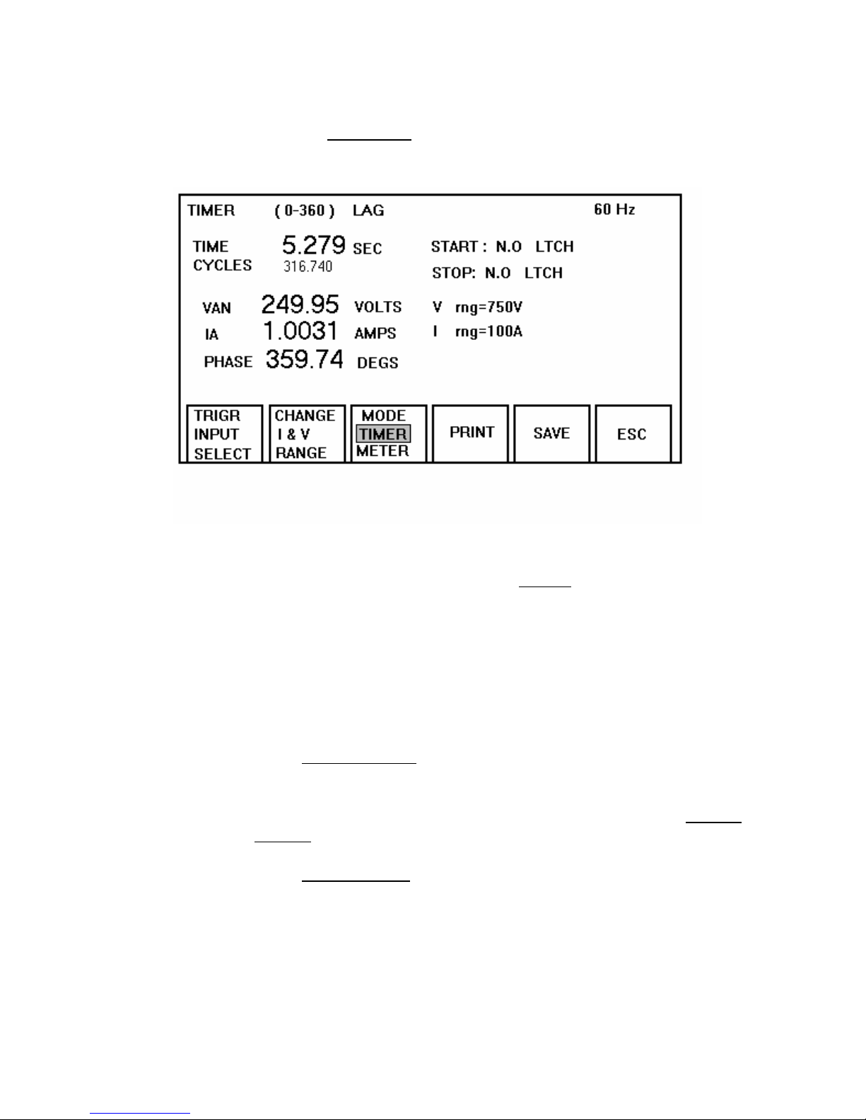
4.9.2 THE MEASURING FUNCTIONS
1. From the Main Menu
, press the TIMER function key.
2. Select the mode of operation, as described in the previous section,
using the appropriate function key. TIMER
is the default mode.
3. The instrument defaults to VAN
and Ia.
4. Manual ranging is also available for this mode of operation. To set
the TRIGGER INPUT, CURRENT and VOLTAGE RANGE select
each one individually and set the desired parameters as previously
described in the manual.
5. In the METER MODE
the timer is disabled, but the voltmeter and
ammeter are operating continuously. The STOP inputs act as a
continuity detector for testing minimum pick-up on protective relays.
When a continuity is detected, a horn will sound. Use the SETUP
PAGE2 screen to disable/enable the horn.
6. In the TIMER MODE the timer is armed and triggered using the
START inputs. The ammeter and voltmeter are also running
continuously. The timer can be stopped using the STOP terminals.
The reading of the ammeter or voltmeter freezes when the timer
stops.
The START / STOP inputs are equipped with a sensing circuitry
that responds to a change of state. This change may be a contact
opening or closing, or the initial application/removal of an AC or DC
28
Page 33

voltage. The input terminals are isolated from the chassis ground
and are independent of signal polarity.
7. To reset the meter, press RESET.
8. Press the SAVE function key to save the content of the display.
Pressing this key will TAG NUMBER the sub-screen. This
information then will be saved in the SAVED DATA DIRECTORY.
9. From the Main Menu, press the VIEW SAVED DATA function key
to view all stored data in the Saved Data Directory.
10. In the SAVED DATA DIRECTORY, use the PAGE DOWN or
PAGE UP function keys to go through the data files. Press the UP
or DOWN arrow keys to cursor to a desired file. Then press the
View Item function key to view the selected file.
11. The PRINT ITEM or XMIT ITEM function keys can also be used to
transmit the data to a printer or a PC. In order to activate the
transmission of the data to an external printer or PC, make the
appropriate connection to the PRINTER and RS232 terminals.
Refer to section 4.13 for more details.
Press the PRINT ITEM and/or XMIT ITEM function keys to initiate
the transmission.
12. Press ESC to return to the previous screen.
4.10 VIEW SAVED DATA Directory
POWER MULTIMETER is equipped with a non-volatile internal memory (28,672
bytes) for saving the test data. The VIEW SAVED DATA features allows the
user to retrieve the save data for download to an external device. The capacity
of the internal memory and the type of measured data are as follows:
CONTENT CAPACITY
Single Phase (50 bytes) 573 sets
Three Phase Wye/Delta (100 bytes) 286 sets
Timer (52 bytes) 552 sets
Single Phase Max Hold (26 bytes) 1102 sets
3-Phase Wye/Delta Max Hold (40 bytes) 716 sets
HS CAPTURE
HS Capture (15 sec/300) (6330 bytes) 4 sets
HS Capture (30 sec/600) (12630 bytes) 2 sets
HS Capture (60 sec/1200) (25230 bytes) 1 set
29
Page 34
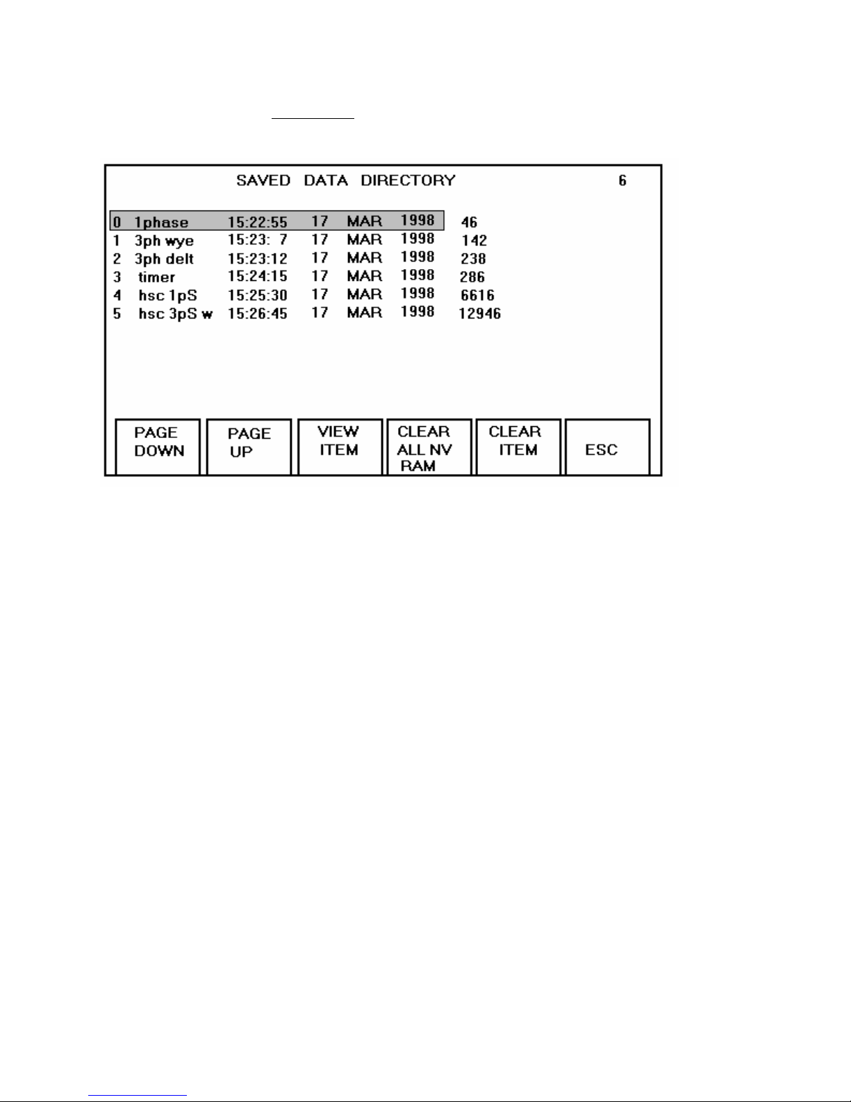
1. From the Main Menu select VIEW SAVED DATA. The following screen
will appear on the display:
A directory containing all saved data will be displayed.
2. To scroll through all files of the directory (if more than one) use the DOWN
and UP
arrow keys. To clear a single file in the directory, press the
CLEAR ITEM.
3. To view the content of the file highlighted press the VIEW ITEM function
key.
Each individual file can be printed or transmitted to an external device by
selecting either the
PRINT ITEM (printer) or XMIT ITEM (RS-232) function
key.
4. To clear one or all saved files in the directory, press the appropriate
CLEAR
function key.
4.11. TIMED DATA TRANSMISSION
For normal single-phase or three-phase measurement the instrument can be
configured so that the data is transmitted to an external PC or printer on a preprogrammed time interval. The interval is programmable from 1 to 60 minutes.
For instance, if a 5 minute interval is selected, the operator can connect the
PMM-1 to a printer, enable the print function and print the measured data every 5
minutes. The following example details the programming of this function:
30
Page 35
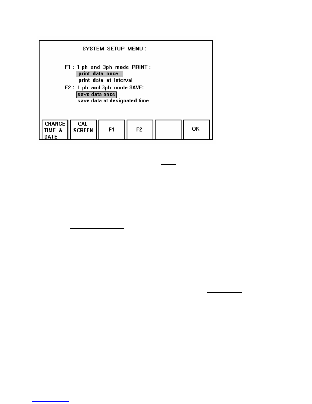
To send data from the printer parallel port proceed as follows:
1. From the Main Menu screen select the More function key.
2. Then select the SetUp Page1 function key to bring up the System SetUp Menu.
3. Use the F1 function key to select either print data once or print data at interval.
4. If the print data once is selected, the user must press the Print function key once
to initiate the data/measured readings out to a printer.
5. If the print data at interval is selected, the user must enter the minutes (1 to 60)
at which the data is to be sent to the connected printer.
6. Return to the measuring screen desired and make the following changes.
7. Select the Set Print Intrvl function key, the Print Interval Select
screen will be
displayed. Use the up ⇑ and down ⇓ arrow keys to increase or decrease the time
of interval transmission.
8. Next toggle the cursor from the Print Disable position to Print Enable
.
9. After completion of the minutes setting, press the OK
function key to initialize the
changes.
10. The Power MultiMeter will begin to send the measured data to the external
device at the set time of transmission.
31
Page 36
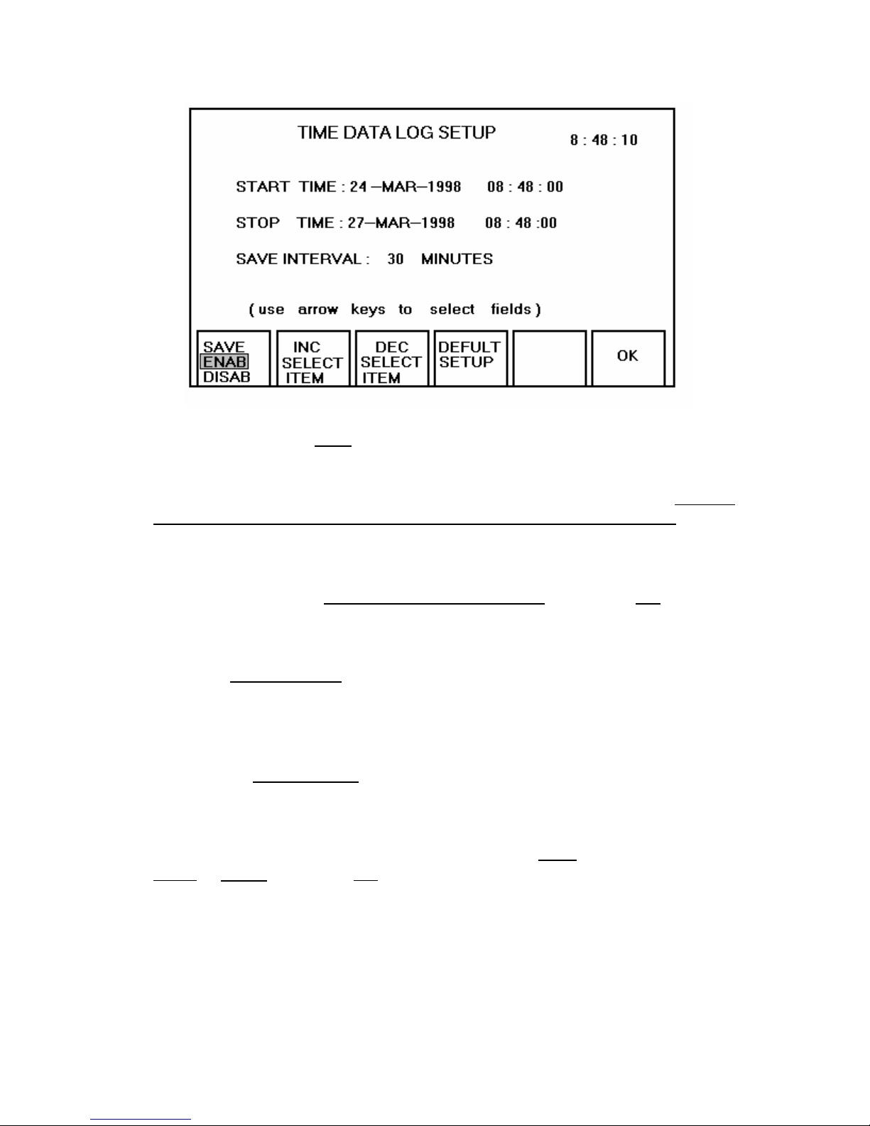
To Save data directly to the NOV
ram, at a set time interval proceed as follows:
1. It is highly recommended that the NOV ram be cleared of all data if possible, this
is to allow maximum use of the unit’s ram memory (28,672 BYTES). Refer to
page 30 of the instruction manual for number of bytes each test uses.
2. From the Main Menu press the More key, then select the SetUp Page1 function
key to bring up the System SetUp Menu. Press the F2 function key once to
toggle the selection to Save data at designated time. Press the OK key.
3. Select the measuring screen desired and make the following changes.
4. Press the Set Save Time function key. From the TIME DATA LOG SETUP
screen use the arrow keys ⇑ ⇓ ⇐ ⇒ to move the cursor to the optional fields.
Here the user can Increase or Decrease the Start/Stop time and the time
interval between each reading.
5. Pressing the Default SetUp function key presets the Start Time to the current
time and date, sets the Stop Time to terminate in 3 days and a Save time interval
of 30 minutes between readings.
6. Once the settings have been completed, press the Save
Disab
to Enab. Press the OK function key to initialize the settings. The Power
function key to toggle
MultiMeter is now ready to begin saving the readings to the NOV ram memory.
7. To stop the recording to the NOV ram at any time, simply press the Esc or Menu
key.
8. To view the saved data, return to the Main Menu and select the View Saved Data
function key.
32
Page 37
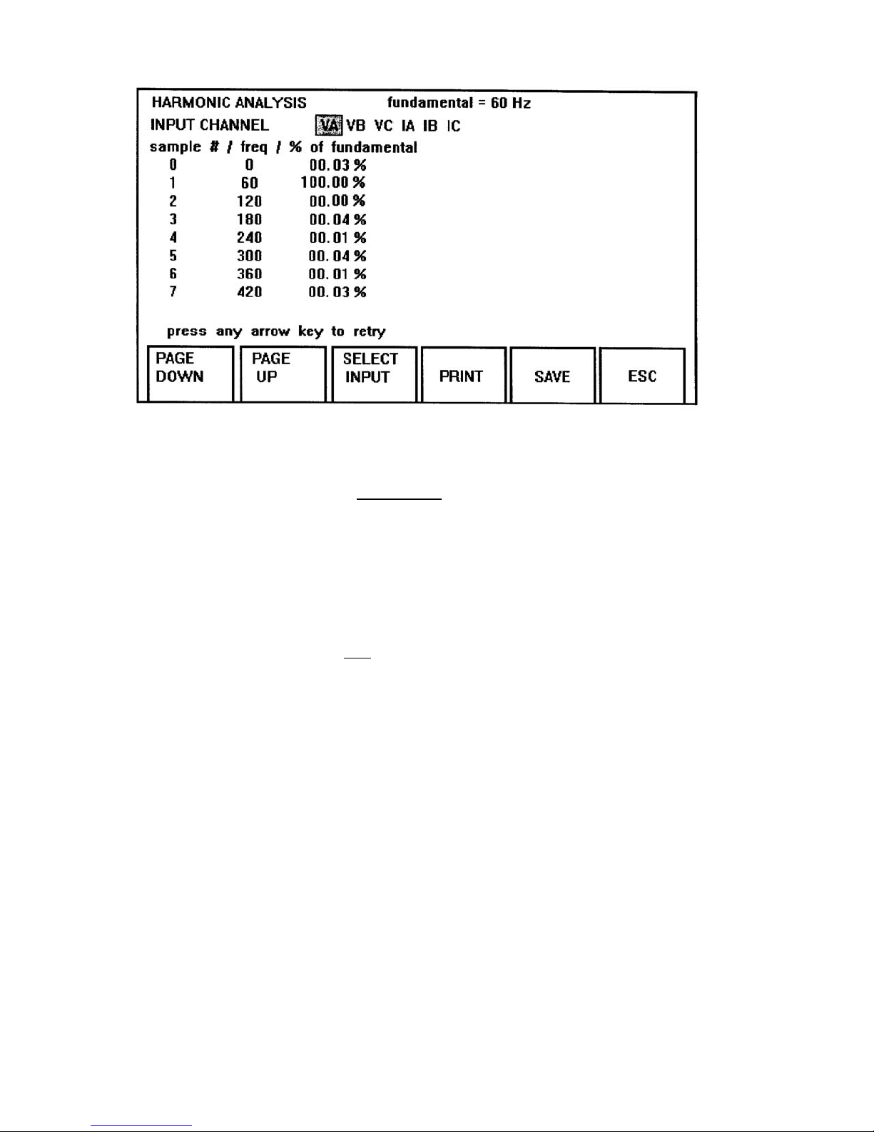
The figure above is the Harmonic Analysis screen, to call up the screen press the
following function keys. From the Main Menu press the More key then select the Harm
function key, the analysis screen will be displayed.
The Harmonic Screen measures the percentage (%) of fundamental for Va, Vb, Vc, IA,
IB, IC. Each parameter can only be measured one at a time. The unit measures the
harmonics up to the 49 th harmonic ( 2940 Hz ). When making a harmonic
measurement on a selection it is important that the user understand that the screen will
not automatically measure and update the screen if a change in harmonics has
occurred. The user must press any arrow key ⇑ ⇐ ⇓ ⇒ to measure or update the
selected voltage or current.
The Harmonic Screen has numerous function keys that allows the user to select after
making the harmonic measurement.
.
• Page Down- this function key moves the data to the next page.
• Page Up- this function key returns the screen to the previous data page.
• Select Input- this function key allows the user to select the desired parameter for
measurement.
• Print- this function key allows the user to send the measured data to a printer.
• Save- this function key saves each measurement to the Save Data Directory.
• ESC- recalls the previous screen.
• Press any arrow key to retry- press any arrow key ⇑ ⇐ ⇓ ⇒ to measure or update
the selected voltage or current.
33
Page 38

4.12. SETTING THE CLOCK AND DATE
The POWER MULTIMETER is equipped with an internal real-time clock and
date, used to stamp the saved data. In order to change the clock and/or date
settings proceed as follows:
1. From the Main Menu
, press the MORE function key. Select SETUP
PAGE1 from the second menu.
2. Press the CHANGE TIME & DATE function key, the current date and time
screen will be displayed. By pressing the Date Select function key the
date field arrangement can be changed.
3. Use the left/right arrow keys to move to the appropriate field (i.e., year,
day, hour, and minutes).
4. Use the up/down arrow keys to change the numbers, as required.
5. To save the new time and/or date press the OK or MENU keys.
4.13. PERIPHERAL OPERATION
4.13.1. PRINTER PORT
The printer port is located on the front panel of the instrument, and uses a
25-pin delta receptacle.
Printer SET-UP Procedures
To send data through the printer parallel port use the following steps:
1. From the Main Menu, press the MORE function key.
2. Select the SetUp Page1
function key to display the System SetUp
Menu.
3. Use the F1 function key to select either print data once
or print data
at interval.
4. If the print data once is selected, the user must press the Print
function key from the measuring screen to initiate the data out to a
printer.
5. If the print data at interval is selected, the user must enter the
minutes at which the data is to be sent to the printer or RS-232
device.
6. Press OK to return to the Main Menu
.
7. Select the measuring screen desired and proceed to make the
following changes.
8. Press the Set Print Intrvl function key, from the Print Interval
screen press the Print ENAB/DISABLE function key once to toggle
to the ENAB positon.
34
Page 39
9. Next, using the up ⇑ and down ⇓ arrow keys, increase or decrease
the desired time of interval transmission (1 to 60 minutes).
10. After completion of the time interval setting, press the OK function
key to initalize the changes.
11. The unit will begin to transmit the measured data to the external
device at the set interval time.
Printer port connector pin-out is shown in TABLE 4-1.
TABLE 4-1. DOT MATRIX PRINTER PORT PIN-OUT
PIN NUMBER DESIGNATION SIGNAL DIRECTION
1 STROBE OUTPUT
2 DATA BIT 0 OUTPUT
3 DATA BIT 1 OUTPUT
4 DATA BIT 2 OUTPUT
5 DATA BIT 3 OUTPUT
6 DATA BIT 4 OUTPUT
7 DATA BIT 5 OUTPUT
8 DATA BIT 6 OUTPUT
9 DATA BIT 7 (MSB) OUTPUT
10 ACKNOWLEDGE
INPUT
11 BUSY INPUT
19-25 SIGNAL GROUND -----
Other pins are not used.
4.13.2. RS232 SERIAL DATA PORT
The serial port is located on the front panel of the instrument, and uses a
9-pin delta plug. The ASCII encoded characters are transmitted at the
19,200
baud rate, with one start bit, 8 data bits, 1 stop bit, and no parity.
The serial port can be directly interfaced to a terminal, a compatible serial
data acquisition system or COM por
ts on any personal computer.
Commonly used software programs such as Windows Terminal, Hyper
Terminal or PROCOMM can be used to collect the data from the
instrument.
35
Page 40
The pin out of the 9-pin delta plug is shown in TABLE 4-2.. Please note
the data transmission is unidirectional
TABLE 4-2. RS232 CONNECTOR PIN-OUT
PIN NUMBER DESIGNATION FUNCTION
2
TxD
3 RxD Receive Data
5 GND Signal Ground
7 CTS Clear To Send
8 RTS Request To Send
Other pins are not used.
Transmit Data
36
Page 41

POWER MULTIMETER COMMAND SET
The Power MultiMeter incorporates an RS-232 Serial Communications Port for
communications with a personal computer.
This feature may be used to transport data
from the measuring instrument to the computer for data analysis and report generation.
Computer Connection
A nine pin RS-232 cable is required to connect the instrument to a communications port
on the personal computer. The connectors on the cable must be male type for the
instrument and normally female type to connect to the computer (Note:
cable is not
null-modem).
The required
Communications Port Settings
Communications through the RS-232 port require the following settings in the
communications software being used on the personal computer:
• Bits per second 19200
• Data
bits 8
• Parity None
• Stop
• Flow
bits 1
Control None
To set up Hyper Terminal to communicate with the PMM-1 do the following:
• Locate Hyper Terminal and open the file.
• Open any ht file, A T & T mail ht, MCI mail ht, etc.
• Click on File, select new connection, message to disconnect will appear. Click on
Yes.
The Connection description box will appear, enter a new connection name.
•
• Click OK, the phone number dialog box will appear.
• Click on the Connect using option, select Direct to Com 1 or appropriate
communication port.
Click OK, the Com 1 properties dialog box will appear.
•
• Make the following changes; change bits per second to 19,200 and Flow Control to
None.
• Click OK
, then select File and Properties to display the “XXX” Properties setting
screen.
• Click Settings
; select Window Keys and Set Emulation to ANSI.
37
Page 42

• Click the ASCII Setup, select Send and Echo. Click OK to complete the setting
changes
Hyper terminal should now be ready to communicate to the PMM-1.
•
• Type in: m1; to change the PMM-1 screen from the main menu to the single-phase
screen.
• Note: commands to the PMM-1 may require double entry before being accepted.
• If the single-phase command is successful, type mpu; to return to the main menu
screen. If both commands are accepted, the communication to the PMM-1 has been
successfully completed.
Power MultiMeter Commands
The following are commands available to control and retrieve data.
IMPORTANT: ALL COMMANDS MUST END WITH A SEMI-COLON ;
Mode commands
Puts Power MultiMeter in a specified operating mode. All commands begin with
“m” . All Mode commands respond with an “AOK!” string for a successful mode
change and a “what?” string if command was invalid.
Measurement Type COMMAND
Single Phase measure: m1;
Three Phase Wye measure: m3y
;
Three Phase Delta measure: m3d;
Power up Menu: mpu;
Timer Mode: mtim;
Hi Speed Capture single phase: mhsc1;
Hi Speed Capture 3 phase wye: mhsc3y
;
Hi Speed Capture 3 phase delta: mhsc3d;
Single Phase Max Hold:
m1max;
3 Phase Wye Max Hold: m3ymax;
3 Phase Delta Max Hold m3dmax;
Single Phase measure with automatic interval query reading feature:
K = interval in minutes. ( Note: when any other command is executed in this
mode the interval query operation is canceled.) m = mode
, 1 = single, i =
m1i,K;
interval, K = minutes
3 Phase Wye measure with automatic interval query reading feature:
K = interval in minutes. ( Note: when any other command is executed in this
m3yi,K;
mode the interval query operation is canceled.)
3 Phase Delta measure with automatic interval query reading feature:
K = interval in minutes. ( Note: when any other command is executed in this
m3di,K;
mode the interval query operation is canceled.)
38
Page 43

Setup commands
Single Phase custom input selection read:
slpcustomr;
sends channel 1 and 2 input source selections ( chan1=0, chan2=6 ) in 0-8
integer format.
0=Van
, 1=Vbn, 2=Vcn, 3=Vab, 4=Vbc, 5=Vca, 6=Ia, 7=Ib, 8=Ic.
See Single Phase, pg 15.
Single Phase custom input selection write:
slpcustomw,m,n;
Write channel 1 and channel 2 input source selections ( same format as read)
m=channel 1, n=channel 2. Note: Once input source settings are changed the
change is not recognized until single phase mode is re-entered ( i.e. ‘ml’
command is re-issued ).
Three Phase mode phase angle reference source selection read:
s3pphrefr;
sends ( phref = 0 ) in 0-5 integer format. 0=Va, 1=Vb, 2=Vc, 3=Ia, 4=Ib, 5=Ic
See Three Phase, pg 20.
Three Phase mode phase angle reference source selection
s3pphrefw,1;
write:
writes in same format as s3pphrefr.
Note: once phase angle reference source setting is changed the change is not
recognized until 3 phase mode is re-entered ( i.e. ‘m3y’ or ‘m3d’ command is
re-issued ).
Hi-Speed capture mode:
sends status i.e., after start or before stop mode setting
changes status, K=0 for after start, K=1 for before stop shscbaw,K;
See High Speed Capture, pg 25.
shscbar;
Sends voltage and current range in any mode:
sranger;
format “vrng=K, irng=L”.
K=voltage range ( 0-7 ):
0 =3.75, 1 =7.5, 2= 15.0, 3=30.0, 4= 75.0, 5= 150.0, 6=300.0, 7=750.0
L=current range ( 0-9 ):
0 =0.2, 1 =0.4, 2 =0.8, 3 =1.6, 4 =3.0, 5 =6.0, 6 =12.0, 7 =25.0, 8 =50.0, 9 =100.0
See High Speed Capture, pg 25.
Change voltage and current range:
Applies to timer and hi-speed capture mode ONLY. All other measurement
srangew,K,L;
modes are autoranging ) Once these ranges are selected they are applied only
on entry to timer mode.
Sends start and stop trigger sources for timer and hi-speed
striggerr;
capture modes
will work in any mode yet applies only to timer and hi-speed capture modes.
39
Page 44

Change Start and Stop trigger sources for timer and hi-speed
striggerw,K,L;
capture modes:
works in any mode yet applies only to timer and hi-speed capture modes.
K=start setting, L=stop setting:
0 for normally open contacts, latch off* 100 for normally open contacts, latch on*
1 for normally closed contacts, latch
101 for normally closed contacts, latch on*
off*
2 for voltage applied, latch off* 102 for voltage applied, latch on*
3 for voltage removed, latch off* 103 for voltage removed, latch on*
( * latch applies to timer mode only, for hi-speed capture a value of 100 is the same
as 0 ).
Sends external CT ratio setting:
sextctr;
format: “ ratio =1 or =200 or =600 or =1000 or =3000”
Change ( write ) external CT ratio setting:
K=1 or =200 or =600 or =1000 or =3000
sextctw,K;
Note: You must re-issue the ‘m1, m3d, or m3y’ for the change
to be recognized.
Sends rms/average voltage setting:
srmsavgr;
This setting affects voltage readings in single and three phase ( wye and delta )
measure modes only
Changes rms/average voltage setting:
srmsavgw,K;
K= 0 for rms, K=1 for avg.
Hi-Speed Capture Specific: arm hi-speed capture function:
hscarm;
Timer Specific: Timer reset:
treset;
Query Command
Transmits all measurement data on display in a comma delimited string. Each
string is terminated with a carriage return line feed.
Query readings:
qr;
The query response string format depends on current operating mode. If current
operating mode does not support a query “not in this mode you don’t”
string will
be returned.
Modes supported: 1 phase, 3 phase ( wye or delta ), timer, and hi
speed capture. )
response formats: 1phase: chan1, chan2,watts, vars, phase ( chan1 to
chan2 ), freq
40
Page 45
3phase: A_volts,B_volts,C_volts,A_amps,B_amps,C_amps
A_watts,B_watts,C_watts,A_vars,B_vars,C_vars
ph_Va_ref,ph_Vb_ref,ph_Vc_ref
ph_Ia_ref,ph_Ib_ref,ph_Ic_ref
A_pwrfact,B_pwrfact,C_pwrfact,freq
timer: status,time_count,A_volts,A_amps,freq
hi speed capture: ( all modes ) one line per sample
sample#,phase i.d.( A,B,C or S ), chan1, chan2,phase (chan1 to
chan2),watts,vars
query time: sends time qt;
query date: sends date qd;
Calibration
Correction Factors: correction factor read:
cfr,m;
read one correction factor specified by m ( 0 <= m <=53 )
cfrm=1 is returned where 1 is the integer value of the correction factor, or if m is
out of the valid range ‘invalid parameter’ message is sent.
correction factor write:
cfw,m,n;
write to one specified correction factor specified by m ( as with cfr ) ‘n’ is the
‘AOK! is returned if change is accepted or ‘invalid parameter’ is returned if either
m or n is out of range or string is not complete or improperly delimited.
send table showing all correction factors:
write bogus test correction factors:
update fudge float array:
Correction Factor x Power MultiMeter Indication = 100 % accuracy
cfa;
cfb;
cfu;
Instrument Correction Factor = 1 + (Correction Factor / 1,000,000)
Correction Factor = (Instrument Correction Factor -1) * 1,000,000
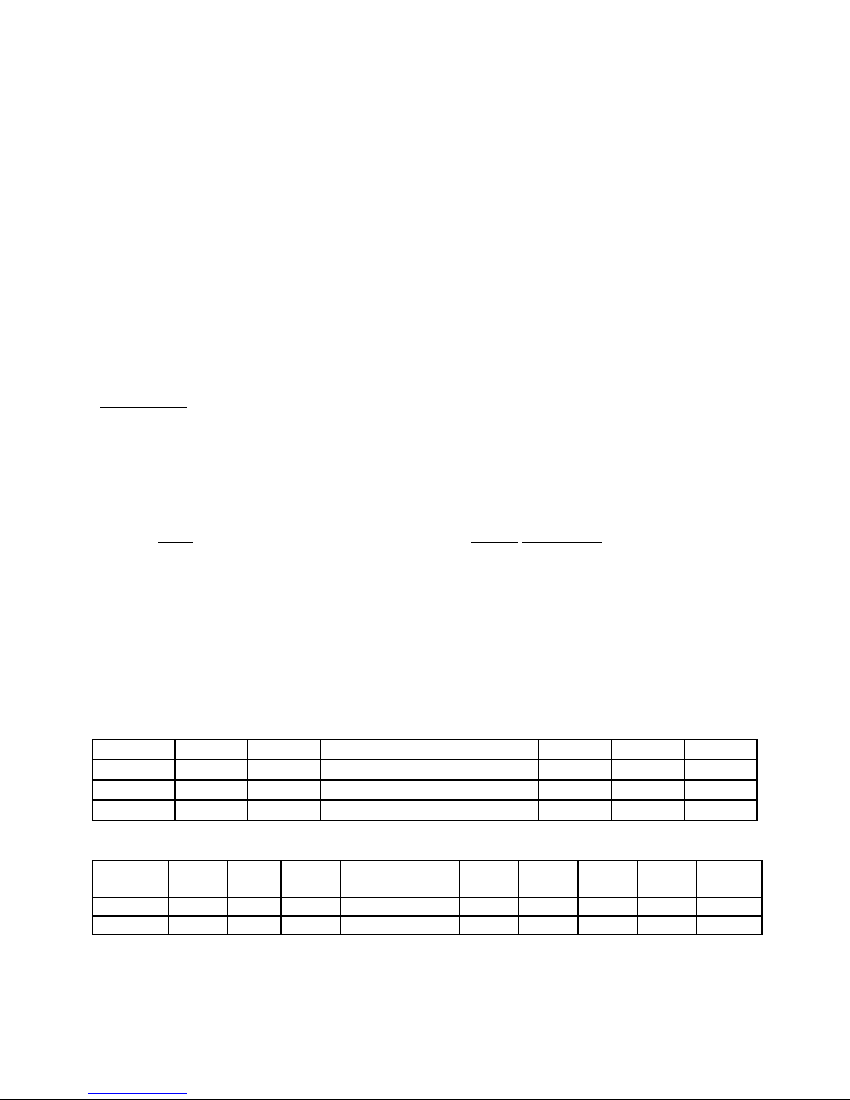
Voltage Correction Factors:
Ranges 3.75V 7.5V 15.0V 30.0V 75.0V 150.0V 300.0V 750.0V
A phase: cf0 cf1 cf2 cf3 cf4 cf5 cf6 cf7
B phase: cf8 cf9 cf10 cf11 cf12 cf13 cf14 cf15
C phase: cf16 cf17 cf18 cf19 cf20 cf21 cf22 cf23
Current Correction Factors:
Ranges 0.2A 0.4A 0.8A 1.6A 3.0A 6.0A 12.0A 25.0A 50.0A 100.0A
A phase: cf24 cf25 cf26 cf27 cf28 cf29 cf30 cf31 cf32 cf33
B phase: cf34 cf35 cf36 cf37 cf38 cf39 cf40 cf41 cf42 cf43
C phase: cf44 cf45 cf46 cf47 cf48 cf49 cf50 cf51 cf52 cf53
POWER MULTIMETER
Calibration Procedures
To check or re-calibrate any range in the Power MultiMeter simply do the following:
41
Page 46

1. Inject a source ( voltage or current ) into the phase or phases in question.
2. Record both readings from the Standard / Reference source and the Power
Multimeter.
3. Use the % error formula to determine how much error the range in question is out
of tolerance.
Standard / Reference reading minus 1 X 100 = % error
Pow
er Multimeter reading
4. 3.00000
minus 1 X 100 = 0.0630 % error
2.99811
5. When a range falls out of tolerance or needs to be re-calibrated, use Windows
Terminal, Hyper Terminal or Procom to communicate to the Power Multimeter.
See communications port settings pg. 39 of the instruction manual.
6. Once communications is established, use the Power Multimeter commands, see
pages 39-42 of the instruction manual . Type in sranger; to inquire the present
range of the voltage and current. Enter the command ( cfa; ) to retrieve all of the
correction factors. Select the range in question and enter the command ( cfr,m; )
to retrieve the correction factors for the range in question. As an example, to
retrieve A-Phase voltage in the 3.75 range the following commands would be
used. cfr,0; this would bring back cfr 0 = xxxx
7. The xxxx’s represent the correction num
ber being used for that range. To enter a
new correction factor in the selected range ( cf0.....etc. ), the old number must be
zeroed out by sending the write command ( cfw,m,n ) to the range. cfw,0,0; this
command writes over the existing correction factor, then type cfu; .
8. To verify the change re-send the read command, cfr,0; this should return cfr, 0 =
0 . Inject the source and record the readings of the Standard unit and the Power
MultiMeter once more. Use the correction formula to calculate the new correction
factor for the range in question.
42
Page 47

9. Example:
Correction factor = [ ( Standard reading / Measured ( PMM1 ) reading - 1 ] x
1,000,000
3.00000 / 2.99811 - 1 x 1,000,000 = 630.397, the new correction factor to be
entered is a positive 630. Enter cfw
, 0, 630; then update by typing cfu; . Inject
the same source and verify that the correction factor has brought the range in
question back into tolerance. Using the % error formula calculate the % error of
the readings.
Keypad
lock keypad: keylock;
unlock keypad: key
unlock;
keypad test mode: keytest;
restore normal key operation after test mode: key
normal;
Note: A screen command (i.e. mpu, m1, m3y…) must be issued to restore
normal key operation.
General
V25 and DSP firmware revision level query: grev;
returns revs in format: V25rev=K.k, DSPrev=L.1.
EXAMPLES
SINGLE PHASE:
Single Phase screen: m1;
query the readings: qr;
Single Phase custom input selection read;
s1pcustomr;
sends channel 1 and 2 input source selections in 0-8 integer format.
( chan1=0 chan2=6 )
0=Van, 1=Vbn, 2=Vcn, 3=Vab, 4=Vbc, 5=Vca, 6=Ia, 7=Ib, 8=Ic.
Single Phase custom input selection write: s1pcustomw
,m,n;
Write channel 1 and channel 2 input source selections ( same format as read)
m=channel 1
, n=channel 2. Note: Once input source settings are changed the change
is not recognized until single phase mode is re-entered (i.e. ‘ml’ command is re-issued).
Changes rms/average voltage setting: srmsavgw
,K;
K= 0 for rms, K=1 for avg.
Lock keypad: key
lock;
Single Phase screen and with automatic interval reading query: m1i,K;
( K = interval in minutes
, 1 minute minimum, 60 minutes maximum ).
( Note: when any other command is executed in this mode the interval query operation
is canceled.)
43
Page 48

THREE PHASE WYE:
Three Phase Wye screen: m3y;
query the readings: qr;
Three Phase mode phase angle reference source selection read: s3pphrefr;
sends ( phref = 0 ) in 0-5 integer format. 0=Va, 1=Vb, 2=Vc, 3=Ia, 4=Ib, 5=Ic
Three Phase mode phase angle reference source selection write: s3pphrefw
Note
: once phase angle reference source setting is changed the change is not
,1;
recognized until 3 phase mode is re-entered (i.e. ‘m3y’ or ‘m3d’ command is re-issued).
Changes rms/average voltage setting: srmsavgw
,K;
K= 0 for rms, K=1 for avg.
Lock keypad: key
lock;
Three Phase Wye screen and with automatic interval reading query: m3y
( K = interval in minutes, 1 minute mi
(Note: when any other command is executed in
nimum to 60 minutes maximum ).
this mode the interval query operation
i,K;
is canceled.)
Unlock keypad: key
unlock;
THREE PHASE DELTA:
Three Phase Delta screen: m3d;
query the readings: qr;
Three Phase mode phase angle reference source selection write: s3pphrefw
Note
: once phase angle reference source setting is changed the change is not
,1;
recognized until 3 phase mode is re-entered (i.e. ‘m3y’ or ‘m3d’ command is re-issued).
Changes rms/average voltage setting: srmsavgw
,K;
K= 0 for rms, K=1 for avg.
Lock keypad: key
lock;
Three Phase Delta screen and with automatic interval reading query: m3di,K;
( K = interval in minutes, 1 minute mi
( Note: when any other command is executed in
nimum to 60 minutes maximum ).
this mode the interval query operation
is canceled.)
44
Page 49

PMM-1 QUICK TIPS
•
If the PMM-1 has been in transient for more than a week, it is very important that the
unit be given a full
charge before being used in the battery operation mode.
• To adjust the screen contrast, press the More function key and use the Less or More
contrast function keys to set the screen contrast.
The PMM-1 is shipped with default settings: Timer Horn
•
-Disabled, Measuring mode-
60 Hz, and Phase Angles 0-360° lag. To makes changes to these settings, press
the More function key, then select Setup Page2. Complete the desired changes
then press the OK or Menu key to initialize the changes.
• Make the proper connections to the voltage and /or current channel inputs.
Connections should be established to the potential and current terminals of
the PMM-1 before the measuring circuit is energized!!!!!!!!!!
• When
measuring DC
volts, the instrument must be in RMS measurement mode only
and positive polarity connected to VA, VB, or VC !!!
PMM-1 defaults to VAN
•
as the phase reference. If current only is measured, the
phase reference must be changed to IA, IB or IC.
To select a CT clamp-on ratio or the customized setup proceed as follows. From the
•
Main Menu, press the More
key, then select SetUp Page2 key. Use the up ⇑ and ⇓
down arrow keys to move the cursor to any of the preset ratios or customized
selection. After changes are completed, press the OK key to initialize the changes.
• High-speed capture samples data at a rate of 20 readings per second and can be
used with single or three phase measurements. The PMM-1 has three sample
selections: 15
sec / 300 samples, 30 sec / 600 samples and 60 sec / 1200 samples.
• Timer operation: When using the timer posts in parallel with another test set, it is
very important that polarity be observed (red and black binding post). If the binding
posts are cross-connected the timer will not function correctly.
• To set the PMM-1 for Timed Data Logging proceed as follows: From the Main
Menu press the More key, select Setup Page1, press the F2 function key to toggle
the selection to Save Data at designated time
Menu select a measurement mode then press the Set Save Time
. Press the OK key. From the Main
key. Using the ⇐
left and right ⇒ arrow keys cursor to the optional fields, press the Inc select or Dec
select item function keys to increase or decrease each field. After making the
changes press the Save function key once to toggle Disab
to Enab then press the
OK function key to initialize the changes.
45
Page 50

• To communicate through the RS-232 port using windows terminal, hyper terminal or
ProComm the following settings are required: bits per second-19,200, data bits-8,
parity-none, stop bits-1, and flow control-none.
EXAMPLES
46
Page 51
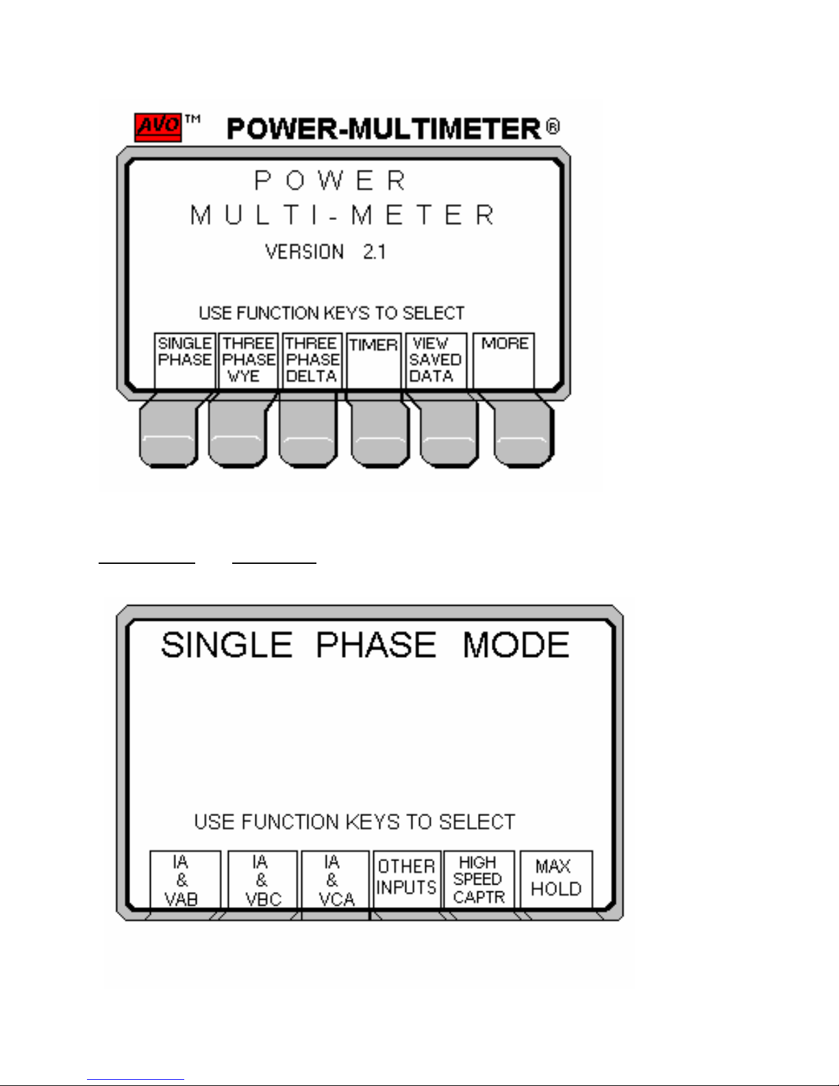
To make a Single Phase, IA and VAB measurement press the following function keys.
Single Phase and IA and VAB, the following screen will be displayed.
47
Page 52
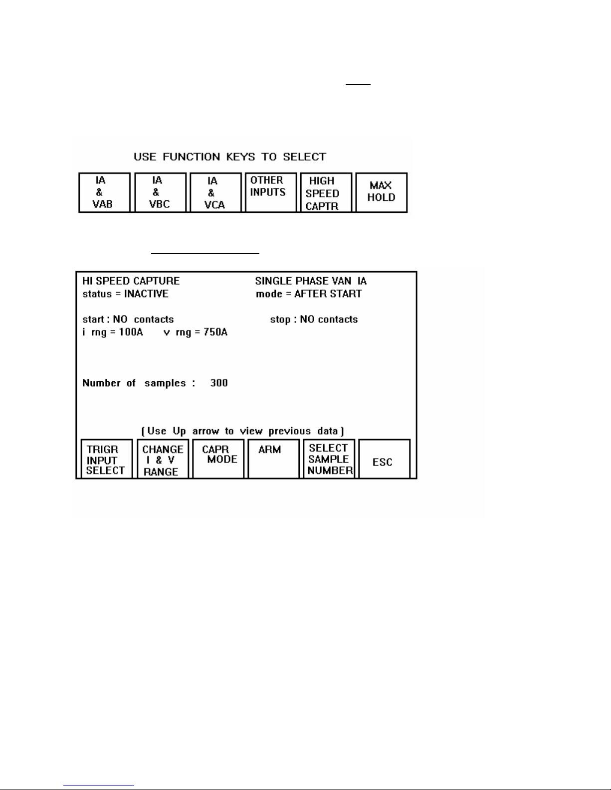
To select another Single Phase configuration press ESC to return to the Single Phase
Menu. In this screen the user can use the Custom Inputs to set up the desired
measurements. The Single Phase Menu also gives you the option of doing a High
Speed Capture measurement on the selected inputs.
After selecting High Speed Capture the following screen will appear.
The High Speed Capture screen has several options the user can set before making the
measurement. It allows the user to change the Trigger Input to the start and stop Timer
binding posts.
48
Page 53
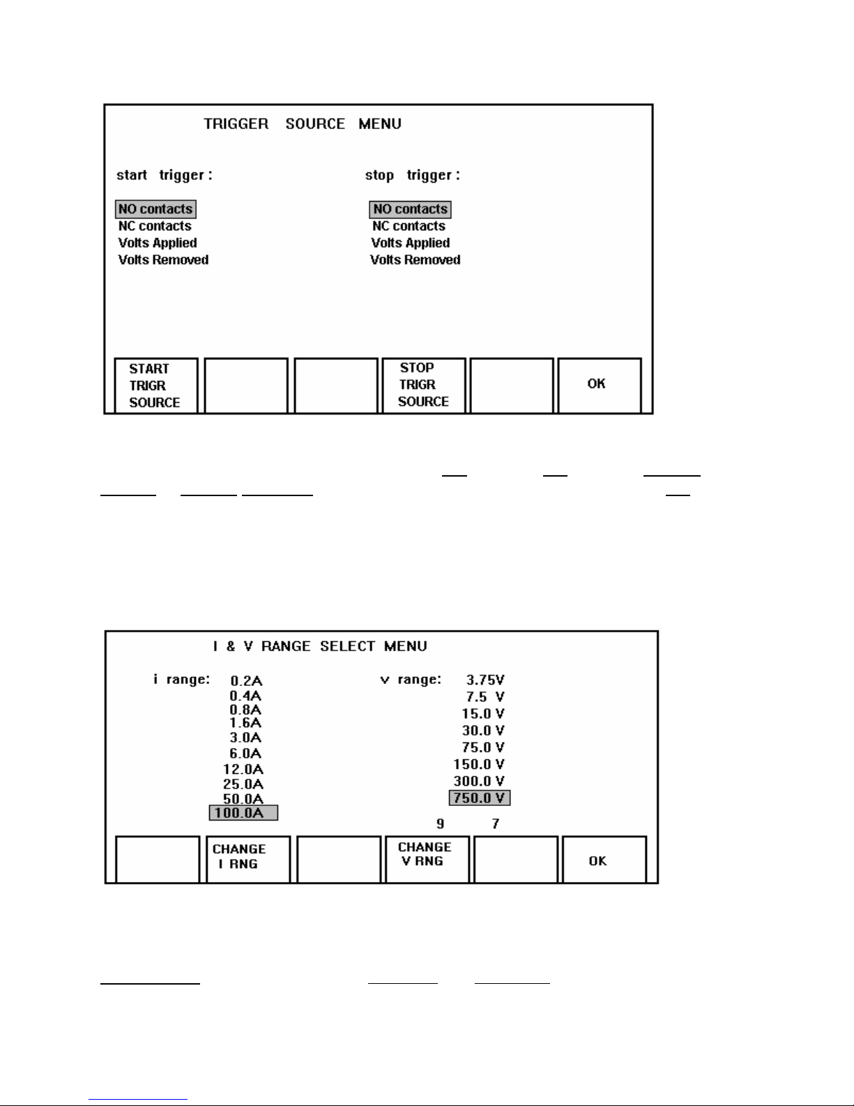
The Trigger Source Menu allows the user the flexibility to set up the Start and Stop
trigger to the desired configuration, that being NO contacts, NC contacts, Voltage
Applied or Voltage Removed. After making the desired selections press the OK
function key to initialize the new configuration and return to the High Speed Capture
screen.
The Power MultiMeter is an auto ranging unit but if the user prefers to set up the
Current and Voltage to the expected measurement range just simply press the Change
I & V Range function key and the following screen will appear.
IMPORTANT Default ranges are 750 Volts and 100 Amps. This mode allows the
user to select and set the voltage and current ranges before initalizing the measurement
test. All ranges have a +20% of the selected range, if the amplitude exceeds the +20%,
49
Page 54
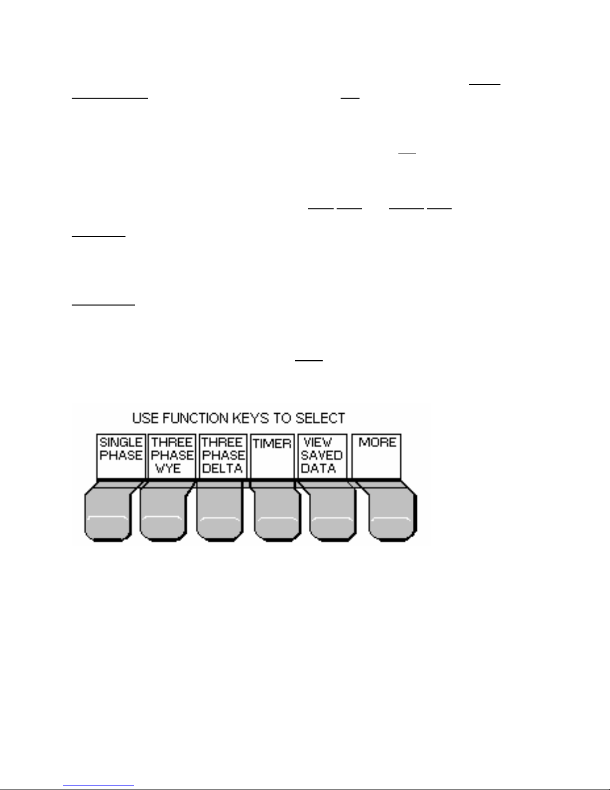
then it must be noted that the resultant values will be considerably off. It is highly
recommended that the ranges selected be at least two ranges above the expected
amplitude or simply just leave it in the defaulted ranges.
In this screen press the Change I RNG or V RNG function keys to move through the
different ranges. Upon making the desired changes press the OK function key to
initialize the new ranges and return to the High Speed Capture screen.
Upon setting the Trigger Input and I and V ranges, the user can then select the Capture
Mode. There are only two options that being After Start and Before Stop.
After Start
: In this mode a maximum of 60 seconds of data can be captured after the
measurement is initiated. Use the START inputs to initiate the measurement. The
measurement will automatically abort (dependent on selection; 15, 30 or 60 SEC) after
it is started.
Before Stop
: In this mode a maximum of 60 seconds of data can be captured. The start
inputs are used to initiate the test and the STOP inputs are used to terminate the test.
Once a High Speed Capture measurement is completed the data can be saved into the
Saved Data Directory by just pressing the Save function key. This option allows the
user to be able to save multiple measurements and later be extracted through the use
of the RS-232 or Printer port.
To conduct a Three Phase Wye measurement simply press the Three Phase Wye
function key and the following screen will be displayed.
50
Page 55
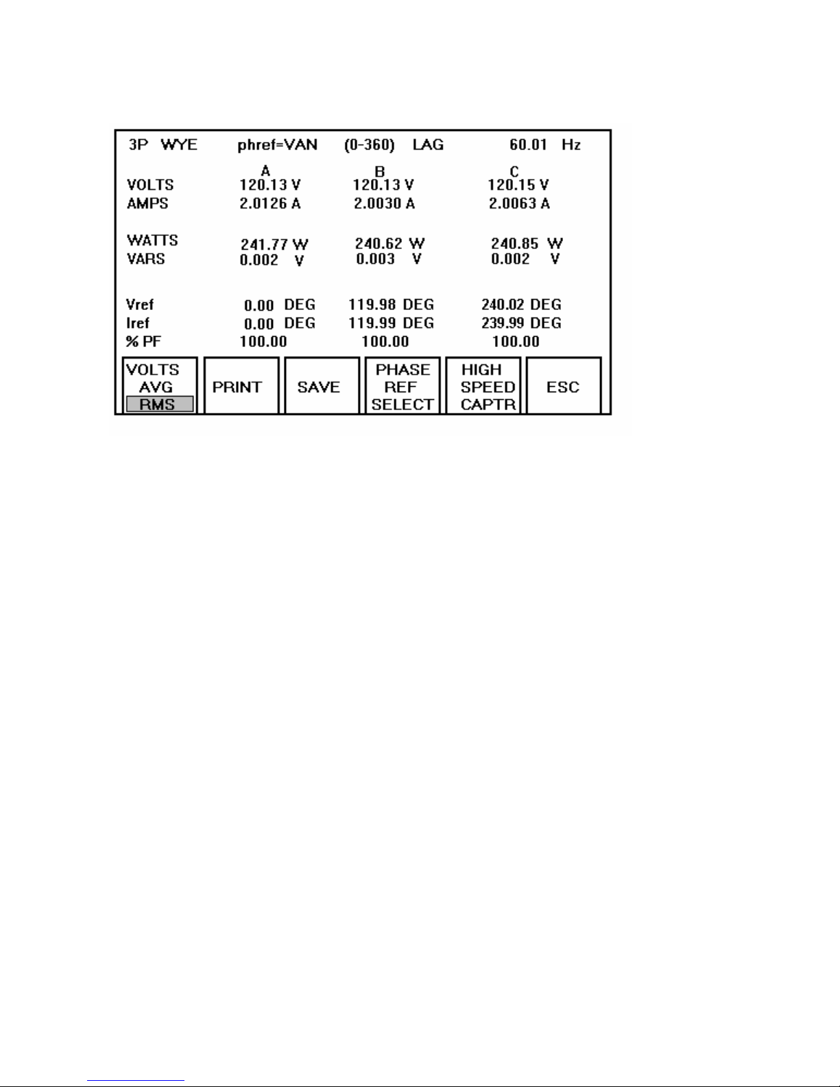
The Three Phase Wye screen has numerous function keys that allows the user to
select for each particular measurement.
• Volts-selection of RMS or AVG mode measurement.
• Print -send measured data to a Parallel Printer.
• Save -save each measurement to the Saved Data Directory.
• Phase Ref Select-change reference point to; VAN, VBN, VCN, IA, IB, or IC.
• High Speed Capture-conduct a high speed test for each measurement.
• ESC - recalls the previous screen.
51
Page 56
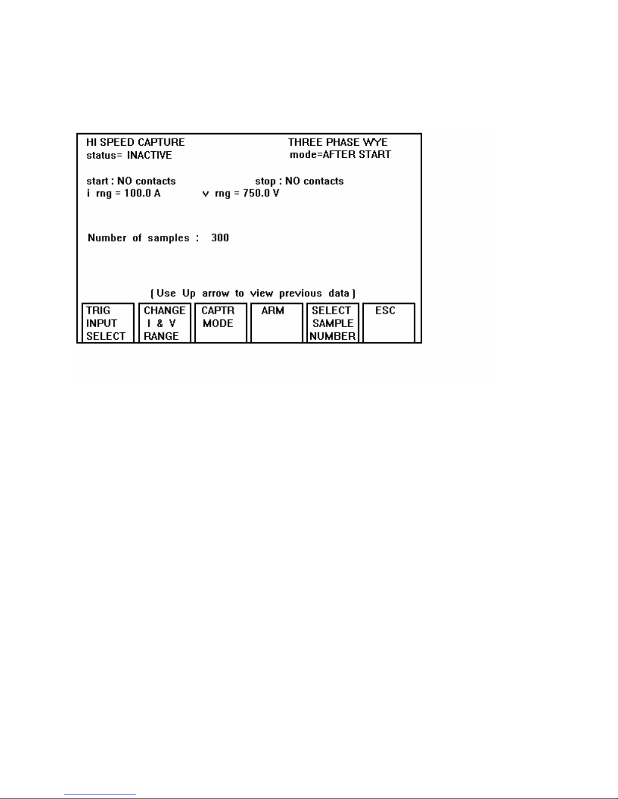
If a High Speed measurement is desired while in the Three Phase Wye or Three Phase
Delta just simply press the High Speed Capture function key and the following screen
will be displayed.
The High Speed Capture screen has numerous function key options that allows the
user to make before conducting the high speed measurement.
• Trigger Input Select-make changes to the Timer start and stop binding posts; NO
or NC contacts, Voltage Applied and Voltage Removed.
• Change I & V Range- change the current and voltage range desired for each
particular measurement.
• Capture Mode-After Start or Before Stop.
• Arm-arms the Power MultiMeter for immediate measurement.
• Select Sample Number-allows selection of; 15 sec/300 samples, 30 sec/600
samples, 60 sec/1200 samples.
• ESC - selection of this function key recalls the previous screen.
52
Page 57
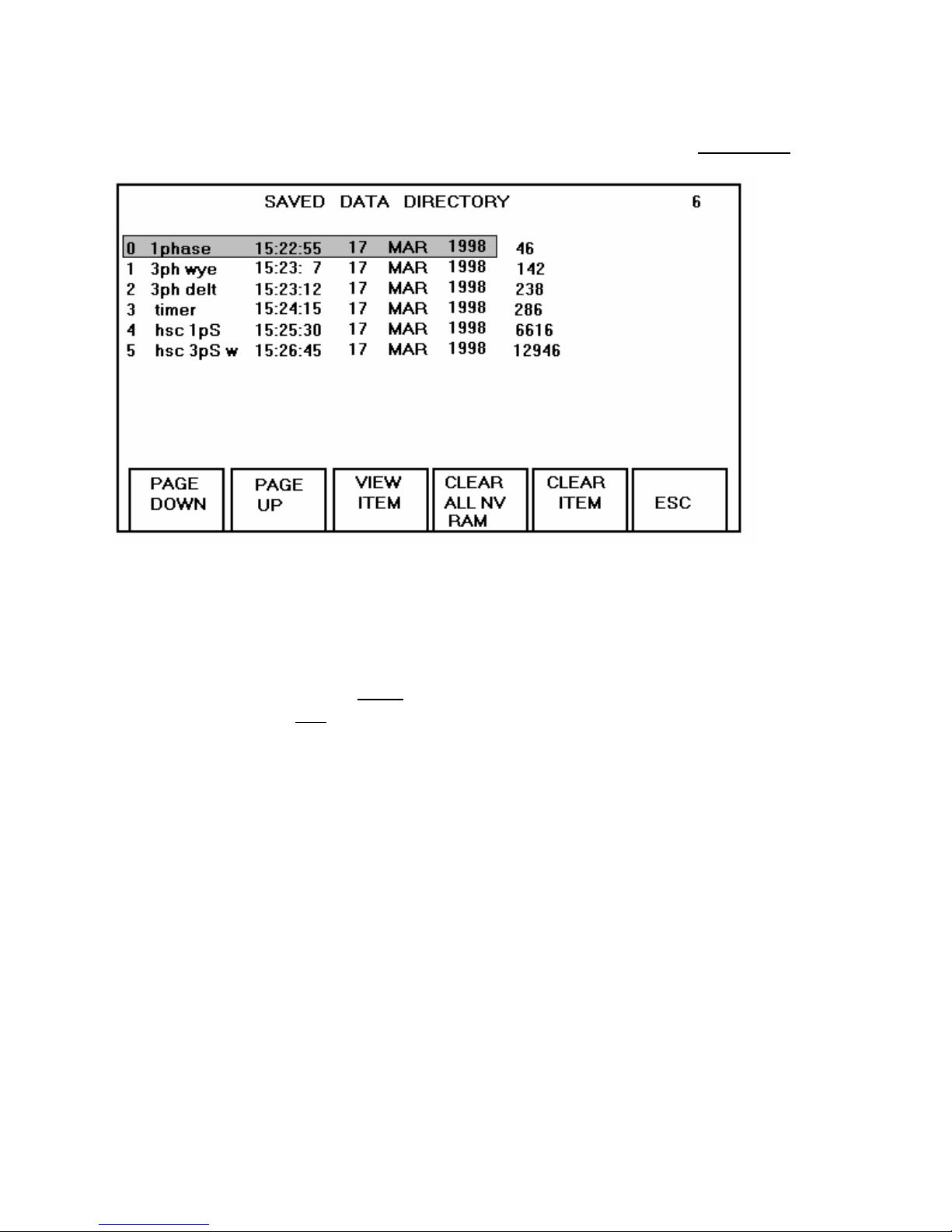
After numerous measurements have been saved and the data is needed for review or
be extracted to a parallel printer or RS-232 device, simply return to the Main Menu and
press the View Saved Data function key and the following screen will be displayed.
The Save Data Screen has numerous function key options.
• Page Down-selection of this function key moves the cursor down to the next page.
• Page Up-selection of this function key moves the cursor up to the previous page.
• View Item-selection of this function key displays the highlighted file for view.
• Clear All NV Ram-Clears every file saved in the NV Ram !!!!!!!!!
• Clear Item-Clears one file at a time. ( File that is highlighted )
• ESC-selection of this function key recalls the previous screen.
53
Page 58
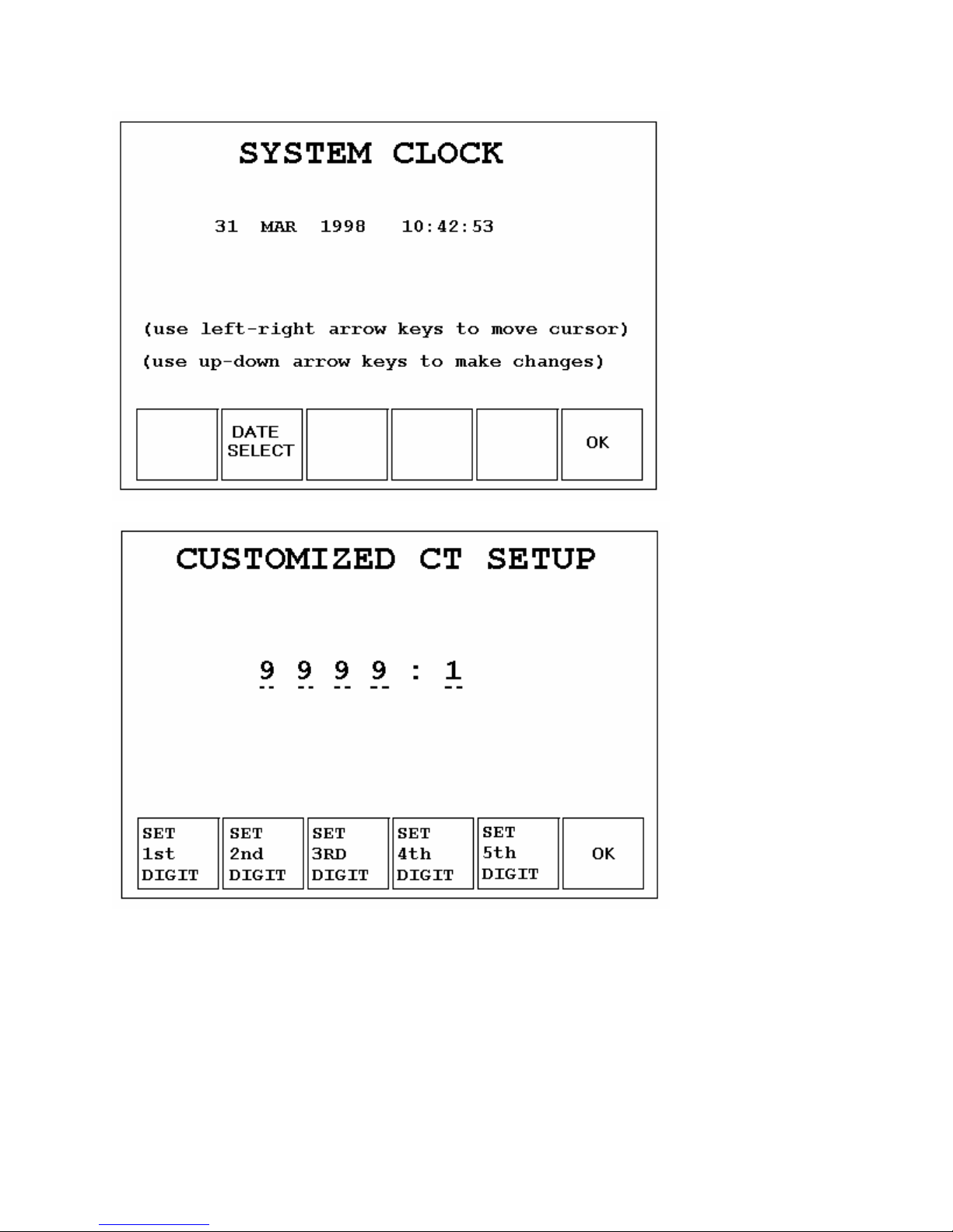
54
Page 59

Power DB PROGRAM INSTRUCTIONS
Instructions for installing the Power DBLite program for use with the Megger Power
Multimeter Model PMM-1.
Computer System Requirements:
Operating System: Microsoft® Windows 2000/XP; minimum 300 MHz PC; minimum
64 MB RAM; CD ROM drive; mouse
Installation from CD
1. Close all applications and insert the CD into the drive.
2. If Autorun is enabled, the CD Setup program will automatically load.
3. If Autorun is not enabled, choose Run from the Taskbar. Type d:\setup.exe and
press the OK button. If CD is not in the D drive enter the appropriate letter.
4. Follow the Setup prompts.
5. After the program has loaded, remove the CD from the computer.
6. Restart / reboot the computer before executing the program.
Installation Via Internet
1. Close all applications. With your machine connected to the internet, Navigate to
powerdb.com.
2. Click on Go To Download
3. Click on Download Power DB Lite
4. Follow the Setup prompts.
5. After the program has loaded, Restart / reboot the computer before executing the
program.
6. Execute the program. Go to Help to view instructions on how to select Your
,
Instrument Setup Screen, how to change the Logos on the test report
and other helpful
information.
55
Page 60
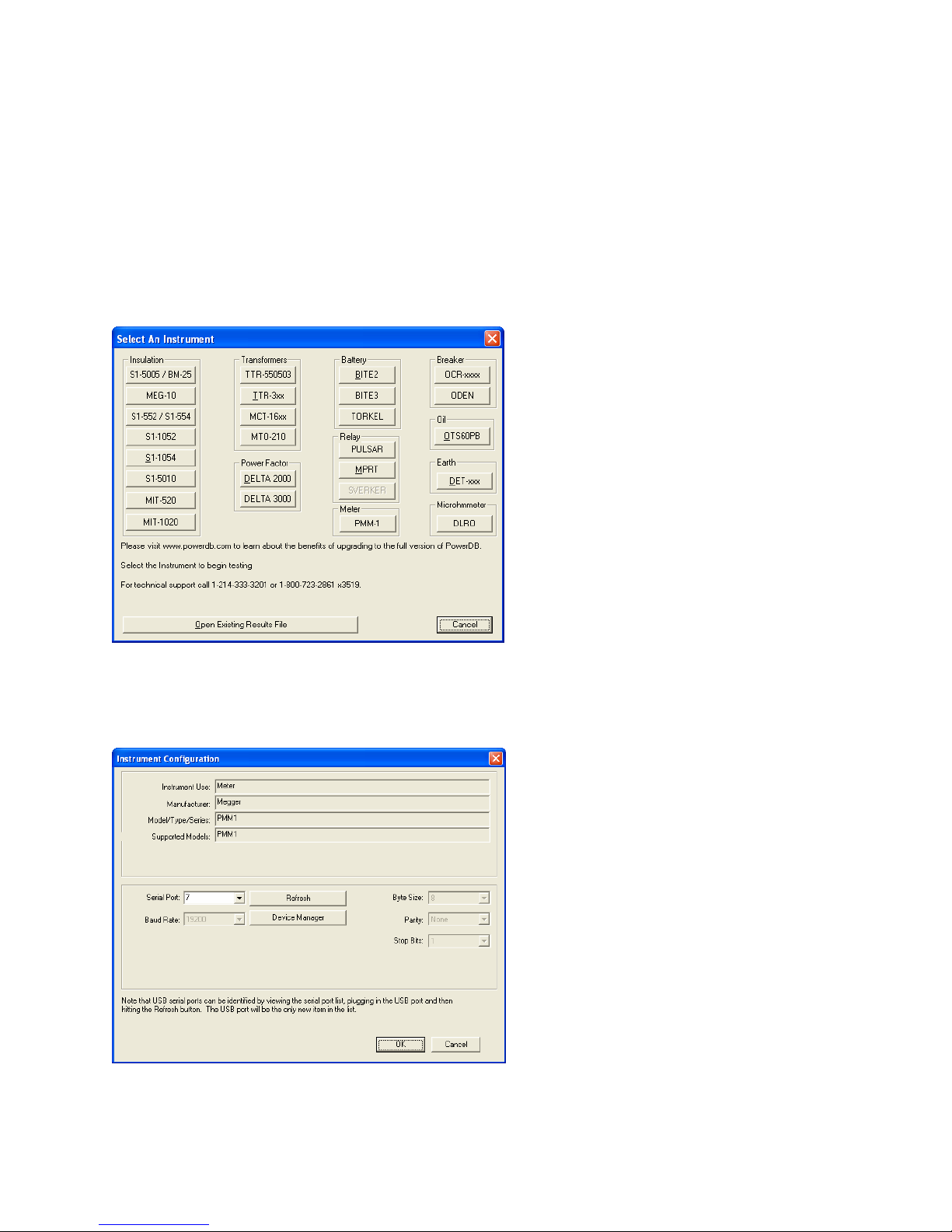
The following are brief explanations of the PMM-1 Power DB user screens and in no
way is intended to be a tutorial on the Power DB Lite program. If more detail operating
instructions is required please refer to the Power DB instruction manual. Some
knowledge of Power DB is required to generate reports.
The following is a brief description of the Power DB Lite software with the PMM-1.
1. Upon opening the Power DB Lite software the user will be presented the Instrument
Selection Screen.
Figure 1 Select Instrument Screen
2. Click on the PMM-1 button. The user will then see the Instrument Configuration
Screen.
Figure 2 Instrument Configuration Screen
3. Click on the Serial Port selection button and select the appropriate communication
port. If you are using a USB to serial adapter you may need to determine which
56
Page 61
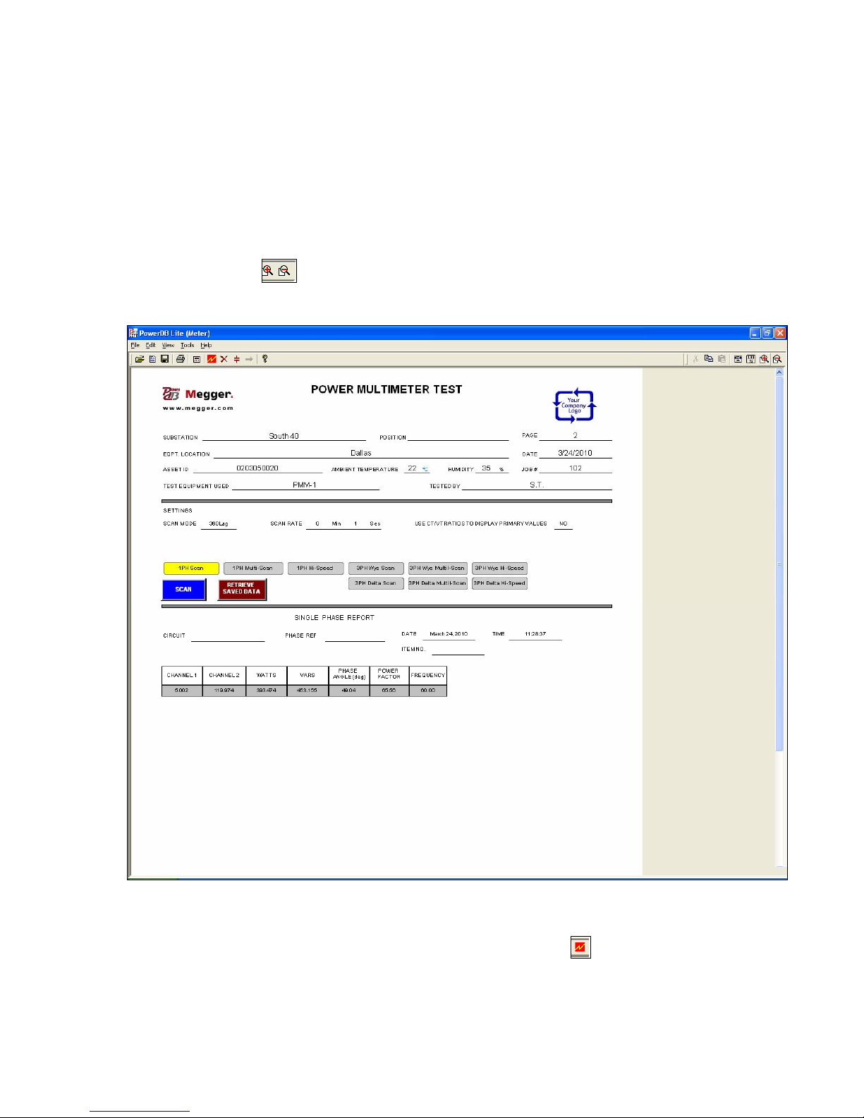
COM Port has been assigned to your USB adapter. To determine the COM Port
assigned click on Start, Control Panel, Performance and Maintenance, System,
Hardware, Device Manager, Ports. The COM Port for your USB to serial adapter
will be displayed. Enter the COM port from the Pull Down window, click on OK.
1 PH Scan
1. Power DB Lite will automatically open the PMM-1 Single Phase test screen. Use
the Zoom button or select Tools, Zoom Out to reduce the form, see an
example reduced form in the following figure.
Figure 3 Single Phase Scan Screen
2. With the serial port properly connected to the PC, establish communications with
the PMM-1 by clicking on the Initializing Instrument button
bar.
located in the tool
57
Page 62
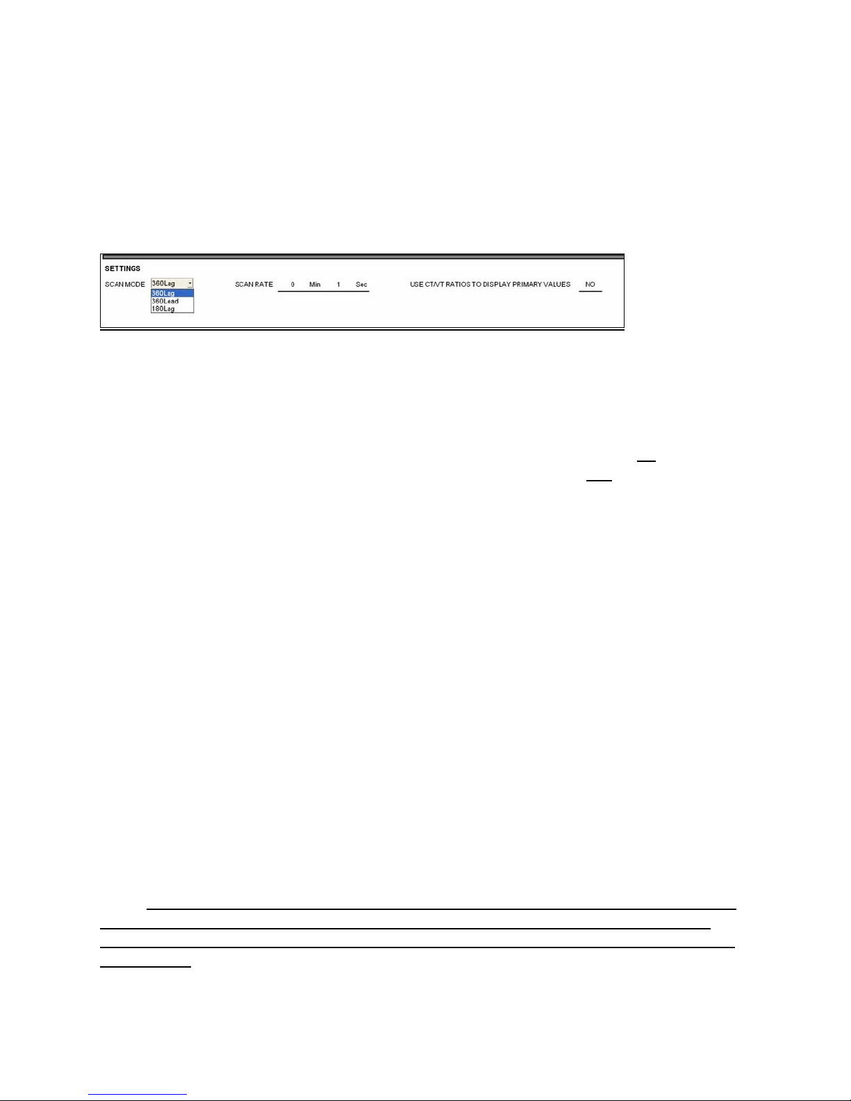
3. Upon establishing communications Power DB will temporally display across the top
of the screen that communication has been successfully established. You are now
ready to use the software with the PMM-1.
4. Select the desired settings for the Scan Mode (360Lag, 360Lead and 180Lag) by
clicking in the SCAN MODE window and use the pull down to select. See the
following figure.
Figure 4 Single Phase Setting Screen
5. Scan Rate: The interval time between measurements. Scan rate can be entered in
minutes and / or seconds. Using the default setting the display in Power DB will
update every second.
6. Use CT/VT ratios to display primary values: (yes or no); Selection of no, sets the
program to display the data in secondary values. Selection of yes, the data
displayed will be in primary values based upon the CT/VT ratios.
You are now ready to use the Single Phase Scan Screen to record data from the
PMM—1. The 1PH Scan has two modes of operation; SCAN and Retrieve Saved
Data. The display will automatically update based upon the SCAN RATE that you set
until the STOP button is pressed. The Retrieve Saved Data mode retrieves a saved file
from the PMM-1. To retrieve the desired file from the PMM-1, go to the PMM-1 MAIN
MENU, press the View Saved Data function key. The Saved Data Directory screen
will appear. Use the up ⇑ or ⇓ down arrow keys to move the cursor to the desired file.
Press the VIEW ITEM function key to recall, display and verify the data on the PMM-1.
To extract the data from the PMM-1 to the Power DB Lite software, mouse click on the
Retrieve Saved Data hot key.
1 PH Mutli-Scan
Pressing the 1 PH Multi-Scan button presents the user with additional settings
requirements, see the following figure. The 1PH Multi-Scan has three modes of
operation; SCAN, Retrieve Saved Data, and START / STOP DATE / TIME. The Scan
PMM mode reads and returns the measured data at the scan rate. To retrieve the data
use the same procedure as outlined above.
Note: It is highly recommended that when making multiple Single Phase, Three Phase
Y or Three Phase Delta Timed Data measurements that a different type of entry be
saved between the Timed Data measurement. The singular saved entry separates the
Timed Data.
58
Page 63
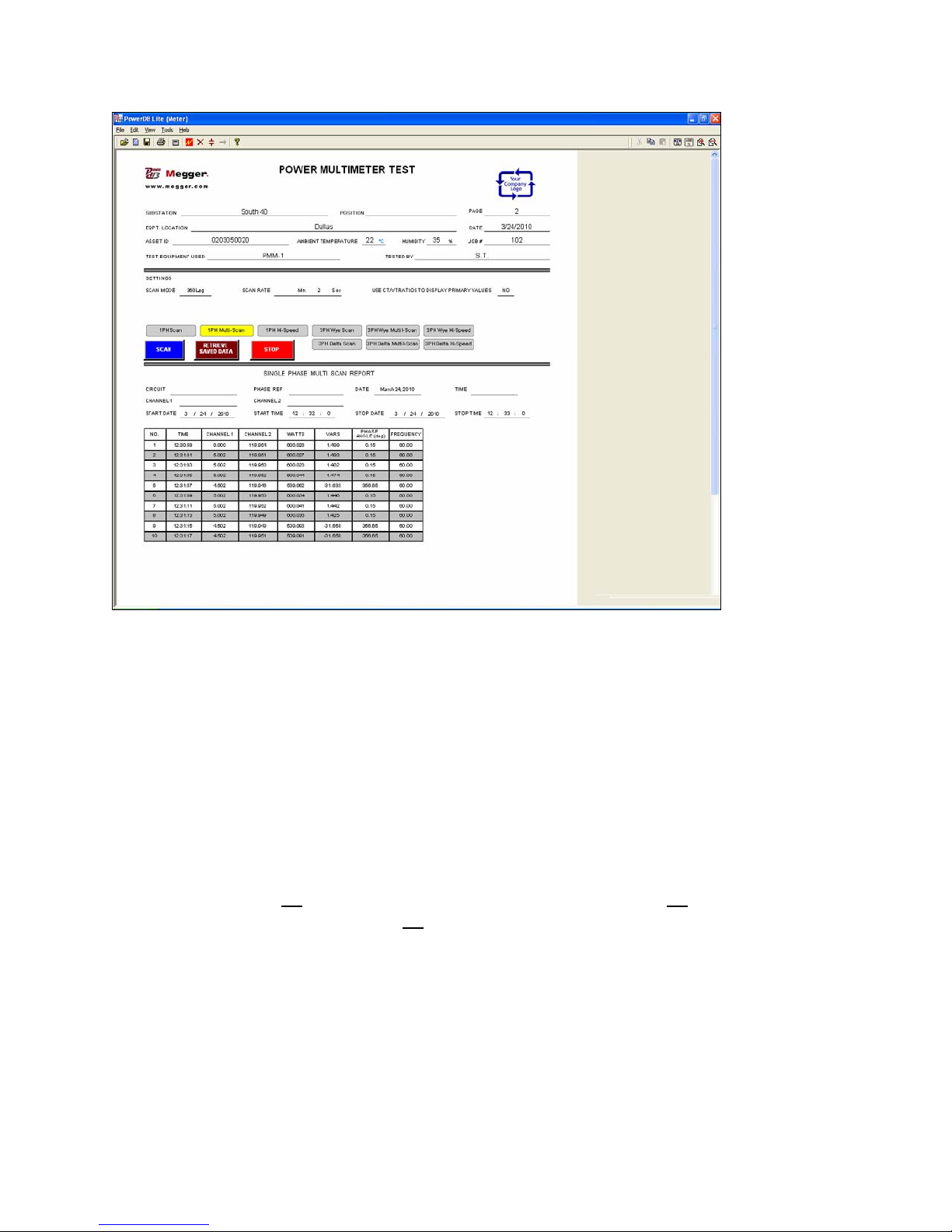
Figure 5 Single Phase Multi-Scan Screen
1. To run Multi-Scan the user will need to set the START DATE, START TIME, STOP
DATE, and STOP TIME. The PMM-1 will start recording based upon the SCAN
RATE at the START DATE and START TIME, and will stop recording at the STOP
DATE and STOP TIME. Press the Scan button to start the process.
2. Either press the Stop button when desired or allow the software to continue to
record data until the Stop Date and Time are reached.
1 PH Hi-Speed
Pressing the Single Phase High Speed button requires the user to input how many
Samples are required (300, 600 or 1200). The sampling rate is taken at 20 readings per
second, thus 300 = (15 seconds x 20 readings per second), 600 = (30 seconds x 20
readings per second), and 1200 = (60 seconds x 20 readings per second), see the
following figure.
59
Page 64
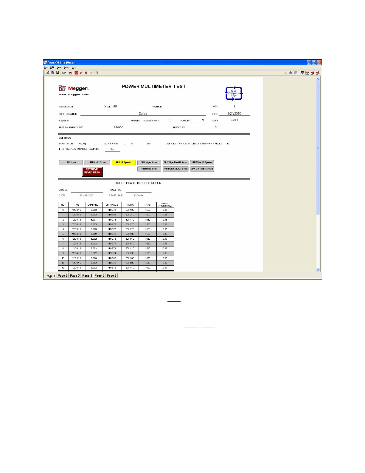
Figure 6 Single Phase High Speed capture Screen
1. The 1PH Hi-Speed screen is used only when there is a need to retrieve a saved
high speed capture file from the Power Multimeter. To retrieve the file, press the
PMM-1 View Saved Data function key. Use the up ⇑ or down ⇓ arrow keys to locate
the desired hsc 1pS file, then press the View Item function key to recall and display
the data.
2. From the Power DB 1PH Hi-Speed screen mouse click the Retrieve Saved Data
hot key to begin transmitting the data.
3 PH Wye Scan
The 3PH Wye Scan has two modes of operation; SCAN and Retrieve Saved Data. The
display will automatically update based upon the SCAN RATE that you set until the
STOP button is pressed. The Retrieve Saved Data mode retrieves a saved file from the
PMM-1, see the following figure.
60
Page 65
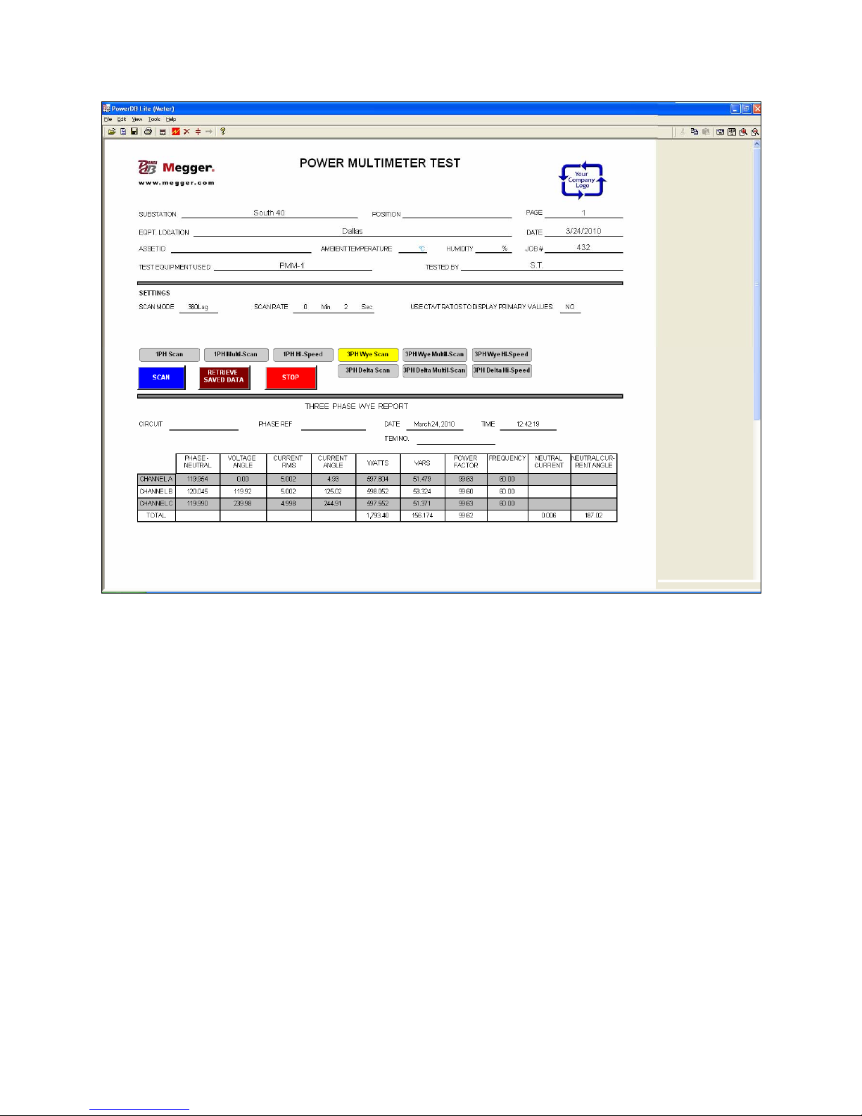
Figure 7 Three Phase Scan Screen
You are now ready to use the Three Phase Scan Screen to record data from the
PMM—1. The 3PH Scan has two modes of operation; SCAN and Retrieve Saved
Data. The display will automatically update based upon the SCAN RATE that you set
until the STOP button is pressed. The Retrieve Saved Data mode retrieves a saved file
from the PMM-1. To retrieve the desired file from the PMM-1, go to the PMM-1 MAIN
MENU, press the View Saved Data function key. The Saved Data Directory screen
will appear. Use the up ⇑ or ⇓ down arrow keys to move the cursor to the desired file.
Press the VIEW ITEM function key to recall, display and verify the data on the PMM-1.
To extract the data from the PMM-1 to the Power DB Lite software, mouse click on the
Retrieve Saved Data hot key.
3 PH Wye Mutli-Scan
Pressing the 3 PH Wye Multi-Scan button presents the user with additional settings
requirements, see the following figure. The 3 PH Wye Multi-Scan has three modes of
operation; SCAN, Retrieve Saved Data, and START / STOP DATE / TIME. The Scan
PMM mode reads and returns the measured data at the scan rate. To retrieve the data
use the same procedure as outlined above.
61
Page 66
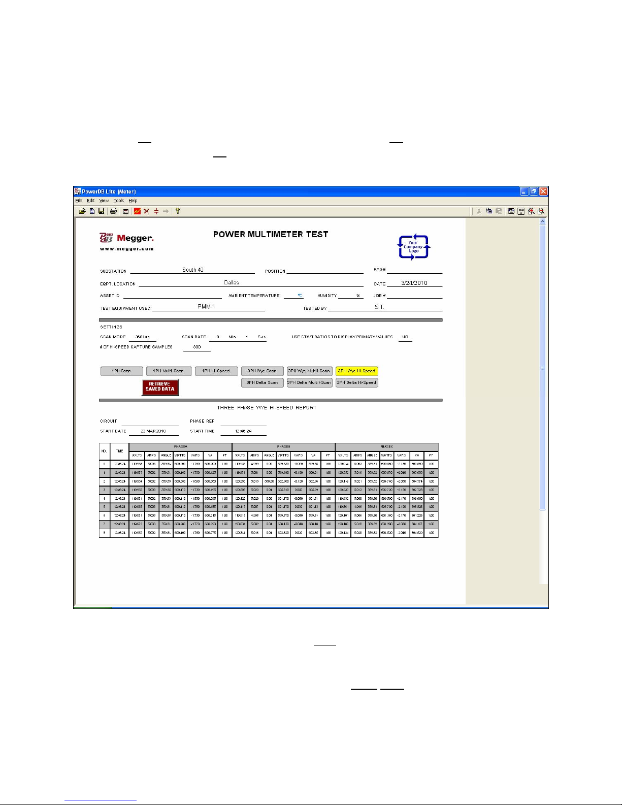
3 PH Wye Hi-Speed
Pressing the 3 PH Wye Hi-Speed button requires the user to input how many Samples
are required (300, 600 or 1200). The sampling rate is taken at 20 readings per second,
thus 300 = (15 seconds x 20 readings per second), 600 = (30 seconds x 20 readings
per second), and 1200 = (60 seconds x 20 readings per second), see the following
figure.
Figure 8 Three Phase High Speed capture Screen
1. The 3PH Wye Hi-Speed screen is used only when there is a need to retrieve a
saved high speed capture file from the Power Multimeter. To retrieve the file, press
the PMM-1 View Saved Data function key. Use the up ⇑ or down ⇓ arrow keys to
locate the desired hsc 3pM file, then press the View
display the data.
2. From the Power DB 3PH Wye Hi-Speed screen mouse click the Retrieve Saved
Data hot key to begin transmitting the data.
Item function key to recall and
62
Page 67
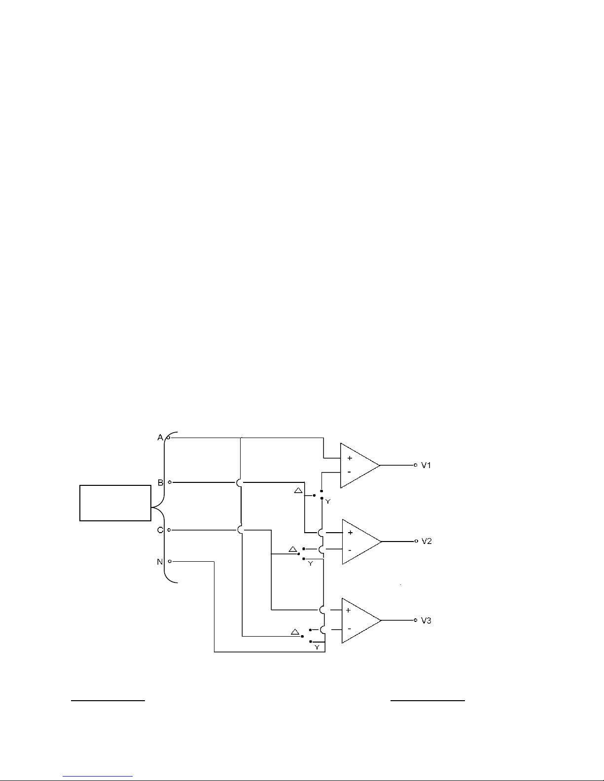
5. SERVICE AND MAINTENANCE
The components and techniques used by Megger are mostly standard and
readily understood by competent, trained technicians. Some calibration and setup procedures, however, are very difficult to perform in the field without the test
jigs and accurate standards available to factory personnel. Customer repair and
calibration are not recommended.Please contact your Megger representative
should service or calibration be required.
6. ADDENDUM – Using PMM-1 for Delta Power Measurements
The North American Addendum Using the PMM-1 Power Multi-Meter
For Delta Power Measurements
Electrical energy is the same regardless of the system configuration in which it is measured. In other
words, 500 watts is 500 watts regardless of whether it is distributed throughout a 3 phase wye (Y) system
or a delta (∆) configured system. Blondel’s Theorem suggests that the number of watt meters required to
accurately measure energy within a circuit is one less than the number of conductors in that circuit. In
keeping with Blondel’s energy measurement philosophy, it becomes necessary to employ a minimum of
two watt meters to measure energy in a delta system, whether it be an open or closed system. Due to
the fact that the PMM-1 does not have a specific preset measurement mode for performing power
measurements using a two watt meter method, the following procedure is set forth for that purpose.
Before going too far into an explanation of how these measurements are made, let’s take a look at a
diagram representing PMM-1 internal connections.
Connections
External
Connections
Y Configuration
= VAN = VA – VN V
V
1
V2 = VBN = VB – VN V
∆ Configuration
63
= VAB = VA - V
1
= VBC = VB - V
2
B
C
Page 68
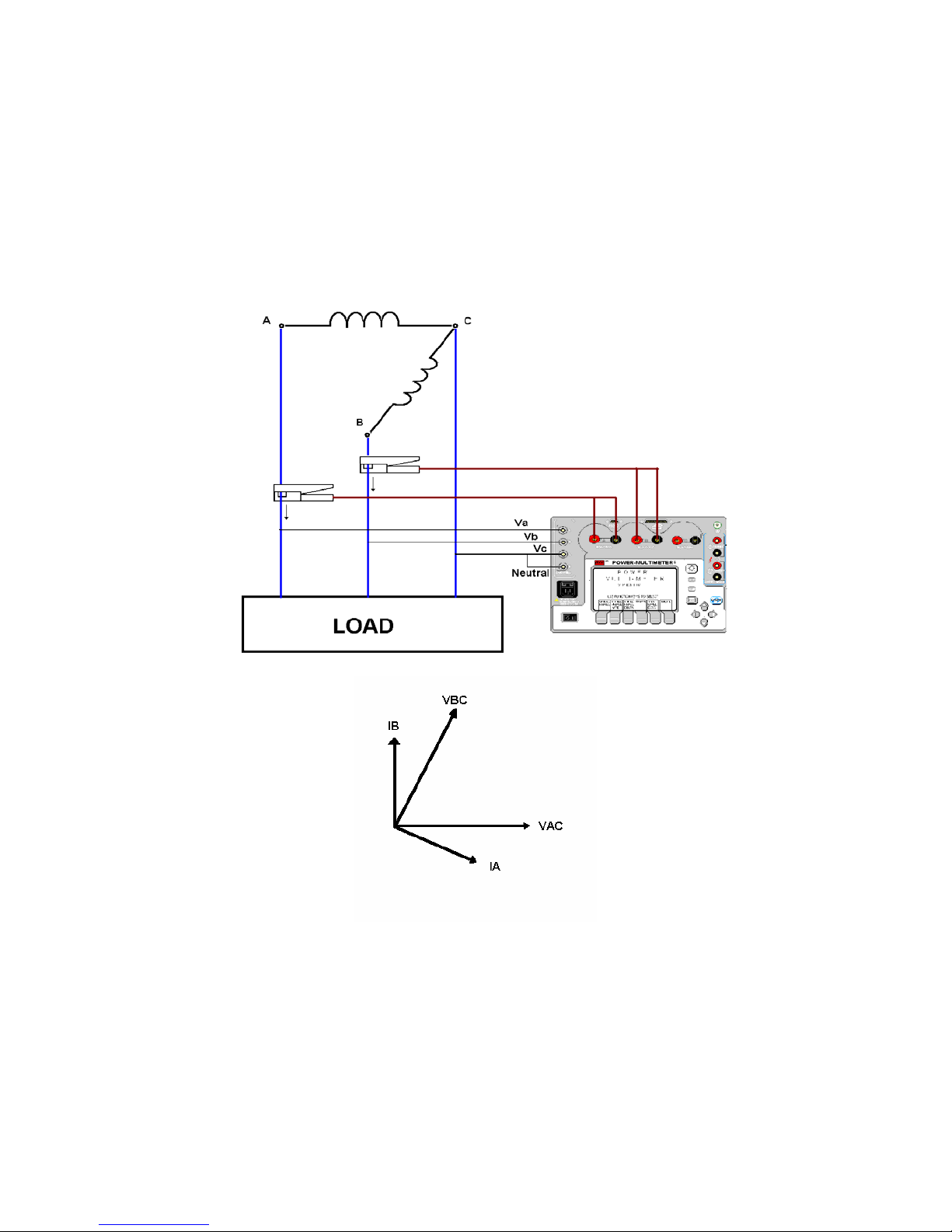
V
= VCN = VC – VN V
3
= VCA = VC - V
3
A
If we choose to use the 3 phase delta measurement mode on the PMM-1, we should assume that it will
use three watt meters, 4 wire measurement process. Unfortunately, when quantities are limited such that
only two watt meters are utilized, this measurement mode will display incorrect power quantities.
By selecting the C phase voltage as the reference, and tying it to the neutral binding post of the PMM-1, a
3 phase wye (ie. line to neutral) measurement mode can effectively be reconfigured for line to line
measurements. Line to line voltage measurements can now be obtained using the 3 phase wye mode of
measurement. The connection diagram in this case would be as follows.
Therefore the anticipated results of such a power measurement would be:
Phase A ═► (V
Phase B ═► (VB-VC) IB = VBC x I
) IA = VAC x I
A-VC
A
B
Phase C ═► (VC-VA) 0 = 0
64
Page 69

The following mathematical exercises are for the purpose of coming to a better understanding of how we
might accurately account for power measurements when monitoring a system of this sort.
∆ Configuration
If we were to assume a balanced load in a closed delta circuit, then we could also assume certain
equalities within the circuit. For the sake of simplicity we will assume the following values and equalities
to use in our calculations.
E
AB=EBC=ECA
I
A=IB=IC
θ=0˚, Power Factor = Cos θ = 1
Where θ represents the phase angle relationship between voltage and current
For this to be true, the voltage and current of each leg must be in phase with one another. Then single
phase power could be calculated as follows.
Total Load Power would equal to the single phase power multiplied by the number of phases.
However, when using the two watt meter measurement method, Ø will become 30 degrees as a result of
using the C phase voltage for our reference in making line to line measurements. Now there are only two
legs that can have current flow in them, according to the above diagram. Power in a delta system will
now have to be based on the voltages and currents in the remaining 2 legs. We will refer to these as P
and P
BC.
= PBC = E x I x √3 x Power Factor
P
AC
Where: θ = 30°, Power Factor = Cos 30° = √3/2 = .866
Total Power Measured
= 2 x 150
= 300 watts
Where we had previously used Cos θ to represent power factor, θ can now be represented in terms of it’s
components. When adding the power factor values for each of the two legs of the circuit being
measured, the sum must be divided by √3. The PMM-1 only displays the individual power factor values
for each individual voltage and current being measured. Therefore, a system power factor can be
calculated by adding the power factors for each of the two legs in the system and then dividing their sum
by √3
= 100 Volts
= 1 Amps
Watts = Voltage x Current x Power Factor
= 100 x 1 x 1
= 100 watts
Total Load Power = # of phases x phase voltage x phase current x Cos θ
= 3 (100)
= 300 watts
The power in each of the two remaining legs can be calculated using the following formula.
= P
AC + PBC
= (EAC x IAC √3 x Cos θ) + (EBC x IBC √3 x Cos θ)
AC
65
Page 70
For example: If the power factor of each of the two legs were Cos 30˚,
then:
= √3/2 = 0.866
PF
AC
= √3/2 = 0.866
PF
BC
Load Power Factor can now be represented in terms of these two components
Load PF = PF
√3
+ PFBC = 0.866 + 0.866 = 1 = Cos θ (30˚)
AC
1.732
%PF = PF(100) = 100%
The following chart is provided as an example of the equality shown in the above equation. Power Factor
may be represented in terms of Cos θ or in terms of the summed power factors from each leg of the
circuit divided by the √3.
Ø
Load
Cos Ø
PF
AC
Cos (30˚+Ø)
PF
BC
Cos (30˚-Ø)
PFAC+ PF
√3
BC
Tot al
Power
-90˚ 0 1/2 -1/2 0 0P
-60˚ ½ √3/2 0 1/2 1/2P
-30˚ √3/2 1 1/2 √3/2 √3/2P
0˚ 1 √3/2 √3/2 1 P
30˚ √3/2 1/2 1 √3/2 √3/2P
60˚ ½ 0 √3/2 1/2 1/2P
90˚ 0 -1/2 1/2 0 0P
.
address and phone number is shown below:
4271 Bronze Way
Dallas, TX 75237-1088
U.S.A.
Phone: (800) 641-2349
Fax: (214)331-7334
66
 Loading...