

Megger PFL40A Instruction Manual

AVTMPFL40A-EN
Rev. C
June 2008
Instruction Manual
Portable Fault Locator
PFL40A
HIGH-VOLTAGE EQUIPMENT
Read this entire manual before operating equipment
M
Valley Forge Corporate Center
2621 Van Buren Avenue
Norristown, PA 19403-2329
U.S.A.
610-676-8500
www.megger.com


Instruction Manual
Portable Fault Locator
PFL40A

Copyright © 2007 Megger. All rights reserved.
The information presented in this manual is believed to be adequate for the intended use of the product.
The products described herein should not be used for purposes other than as specified herein.
Specifications are subject to change without notice.
WARRANTY
Products supplied by Megger are warranted against defects in material and workmanship for a period of
one year following shipment. Our liability is specifically limited to replacing or repairing, at our option,
defective equipment. Equipment returned to the factory for repair must be shipped prepaid and insured.
This warranty does not include batteries, lamps, or other expendable items, where the original
manufacturer's warranty shall apply. We make no other warranty. The warranty is void in the event of
abuse (failure to follow recommended operating procedures) or failure by the customer to perform
specific routine maintenance as indicated in this manual.
M
Valley Forge Corporate Center
2621 Van Buren Ave
Norristown, PA 19403-2329
610-676-8500 (Telephone)
610-676-8610 (Fax)
www.megger.com

Table of Contents
Upon Receipt of Product.........................................................................................................................................1
1 GETTING TO KNOW THE PFL..................................................................................................................3
1.1 Top Panel Controls ................................................................................................................................3
1.2 Rear Panel Connections.........................................................................................................................4
2 SAFETY ................................................................................................................................................................5
2.1 Safety is the responsibility of the user .................................................................................................5
2.2 General Safety Precautions....................................................................................................................5
2.3 Safety in Using the PFL.........................................................................................................................6
3 PREPARING FOR TEST .................................................................................................................................7
3.1 Site Preparation.......................................................................................................................................7
3.2 Making Circuit Connections .................................................................................................................7
4 CABLE TESTING ............................................................................................................................................ 11
4.1 Main Menu Operation ........................................................................................................................ 11
4.2 Typical Fault Location Strategy ......................................................................................................... 12
4.3 ARC Reflection Method..................................................................................................................... 13
4.4 Impulse Current (Surge) ..................................................................................................................... 14
4.5 Pulse Echo (Time Domain Reflectometry, TDR) .......................................................................... 17
4.6 Cable Burn Down (Fault Conditioning)........................................................................................... 18
4.7 Dielectric Test (Proof) ........................................................................................................................ 19
4.8 Decay Test (Optional Accessory)...................................................................................................... 20
5 SYSTEM WARNINGS.................................................................................................................................... 23
Warning Messages:............................................................................................................................................ 23
6 DE-ENERGIZE AND SYSTEM SHUTDOWN...................................................................................... 25
7 MAINTENANCE ............................................................................................................................................ 27
7.1 Pre-Maintenance Precautions ............................................................................................................ 27
7.2 Inspection and Maintenance .............................................................................................................. 27
7.3 Repairs................................................................................................................................................... 28
8 SPECIFICATIONS.......................................................................................................................................... 29
Available Modes ................................................................................................................................................ 29
Voltage Output.................................................................................................................................................. 29
Current Output.................................................................................................................................................. 29
Energy................................................................................................................................................................. 30
Coupling.............................................................................................................................................................. 30
Metering.............................................................................................................................................................. 30
Environmental ................................................................................................................................................... 30
Physical ............................................................................................................................................................... 31
Input Voltage Source (User specified) ........................................................................................................... 31
Standard Accessories ........................................................................................................................................ 31
Optional Modules/Accessories....................................................................................................................... 32
AVTMPFL40A-EN Rev C June 2008
i

Addendum A MTDR Analyzer........................................................................................................................33
Specifications ......................................................................................................................................................33
Top Panel Controls............................................................................................................................................35
Communications ports......................................................................................................................................35
Home Screen.......................................................................................................................................................36
Home Screen - Mode Options.........................................................................................................................36
Utilities.................................................................................................................................................................37
Test Parameters – Display Header ..................................................................................................................38
Trace Viewer Control ........................................................................................................................................39
TDR - Multiple Trace Capture.........................................................................................................................40
Arc Reflection – Test Contro...........................................................................................................................41
Impulse Current (Surge)....................................................................................................................................42
Decay Method ....................................................................................................................................................42
MTDR Lead length Calibration - Left Cursor Offset ..................................................................................43
Troubleshooting .................................................................................................................................................44
Addendum B CBL100HV Cable Reels...........................................................................................................45
Connections ........................................................................................................................................................45
Specifications ......................................................................................................................................................46
Connecting the Cable Reels..............................................................................................................................46
Addendum C COMLink (Version 1.08).........................................................................................................49
Introduction........................................................................................................................................................49
Software Installation ..........................................................................................................................................50
Connecting the PC to the MTDR ...................................................................................................................50
COMLink Home Screen...................................................................................................................................51
Transferring Wave Forms from the MTDR ..................................................................................................53
Multiple Waveform viewing .............................................................................................................................55
Print Waveform..................................................................................................................................................55
Communications functions...............................................................................................................................55
Setup Serial Port.................................................................................................................................................56
COM32................................................................................................................................................................56
AVTMPFL40A-EN Rev C June 2008
ii

List of Figures
PFL40A Cable Fault Location System...................................................................................................................1
Figure 1-1. Top Panel Controls ..............................................................................................................................3
Figure 1-2. Rear Panel Connections.......................................................................................................................4
Figure 3-1 PFL40A Connection Diagram.......................................................................................................... 10
Figure 4 1: Main Control Menu........................................................................................................................... 11
Figure 4-2. Decay Coupler Connections ............................................................................................................ 22
Figure B-1. High-Voltage and Ground Cable Reel connections. ................................................................... 45
Figure C-1. COMLink Installation screen.......................................................................................................... 50
Figure C-2. COMLink Home Screen.................................................................................................................. 51
Figure C-3. Successful Connection Confirmation Screen ............................................................................... 51
Figure C-4. Select Operating Mode Screen........................................................................................................ 52
Figure C-5. MTDR Waveform Viewer............................................................................................................... 52
Figure C-6. File Transfer Menu ........................................................................................................................... 53
Figure C-7. MTDR Waveform Viewer............................................................................................................... 54
Figure C-8. MTDR Waveform Viewer – Control Box .................................................................................... 55
Figure C-9. Serial Port Set Screen........................................................................................................................ 56

M
iv
AVTMPFL40A-EN Rev C June 2008

Upon Receipt of Product
Prior to operation, check for loosened hardware or damage incurred during
transit. If these conditions are found, a safety hazard is likely, DO NOT attempt
to operate equipment. Please contact Megger as soon as possible.
AVTMPFL40A-EN Rev C June 2008
PFL40A Portable Cable Fault Location System
1

M
M
2
AVTMPFL40A-EN Rev C June 2008
1
GETTING TO KNOW THE PFL
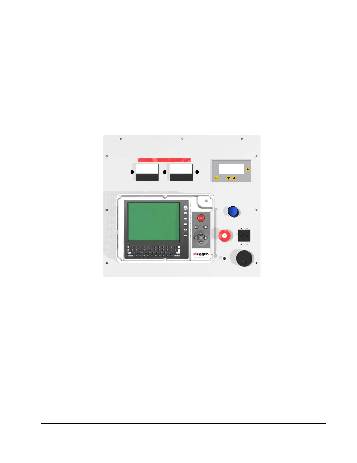
1.1 Top Panel Controls
7
7
89
10
10
89
12
11
11
MTDR
MTDR
12
3
3
4
4
2
2
1
1
1. Power ON/OFF and Circuit Breaker
2. Emergency OFF (available with key option)
3. Main Menu Controller (See Section 4.1)
4. Dielectric Test Current Limit Control (See Proof Section 4.7)
5. Voltage Rate knob (controls the rate at which Voltage Control operates)
6. Voltage Control
7. High Voltage Power Supply ON Indicator
8. Voltage Meter (4/40kV dual range)
AVTMPFL40A-EN Rev C June 2008
5
5
Figure 1-1. Top Panel Controls
3
6
6

M
1.2 Rear Panel Connections
9. Current Meter (30/300 mA dual range)
10. 4kV (Optional module) Range Indicator
11. +24V Indicator (illuminates when Circuit Breaker is ON)
12. 30 mA Range indicator (active during Proof mode only)
1
1
3
3
2
2
89
89
7
7
5
5
4
4
6
6
Figure 1-2. Rear Panel Connections
1. External Warning Beacon circuit
2. Safety Interlock circuit
3. Input Power Connector
4. High-Voltage Output Receptacle
5. Ground Chassis Lug
6. Air Intake Fan (DO NOT BLOCK WHILE UNIT IS OPERATING)
7. Air Exhaust Fan (DO NOT BLOCK WHILE UNIT IS OPERATING)
8. Decay Coupler Input (optional)
9. External Ground Monitor Probe Input (optional)
4
AVTMPFL40A-EN Rev C June 2008

2
SAFETY
2.1 Safety is the responsibility of the user
Only qualified and trained operators should operate the PFL40A system.
Operator must read and understand this entire Instruction Manual prior to
operating the equipment. Operator must follow the instructions of this
Instruction Manual and attend the equipment while the equipment is in use. In
the event of equipment malfunction, the unit should immediately be deenergized and returned to Megger for repair.
2.2 General Safety Precautions
The PFL40A and the Cable Specimen (containing the fault) are both sources of
instantaneously lethal levels of electrical energy. Observe the following safety
precautions:
Observe all safety warnings on the equipment. They identify areas of
immediate hazard that could result in injury or death.
Use this equipment only for the purposes described in this manual. Observe
strictly the Warning and Caution information provided in this manual
Treat all terminals of high-voltage power equipment as potential electric
shock hazards. Use all practical safety precautions to prevent contact with
energized parts of the equipment and related circuits.
Use suitable barriers, barricades, or warnings to keep persons not directly
involved with the work away from test activities.
Never connect the test equipment to energized cables.
Do not connect to energized equipment or use in an explosive atmosphere.
Use the grounding and connection procedures recommended in this manual.
Personnel using heart pacemakers should obtain expert advice on the
possible risks before operating this equipment or being close to the
equipment during operation.
AVTMPFL40A-EN Rev C June 2008
5

M
2.3 Safety in Using the PFL
Never assume that either the PFL40A High-Voltage Output Cable or the
Cable Specimen is de-energized. Always treat exposed conductors and
connections as potential electric shock hazards
Do not use this equipment to locate faults on direct-buried unshielded or
secondary cable. Otherwise, dangerously high differences in potential may be
developed in the Surge Return path.
Do not use this equipment to locate faults on any cable that may be close
enough to an energized cable to allow a burn-through of the insulation of the
energized cable.
Do not operate the equipment without all metal panels securely fastened.
Do not operate the PFL if it has not first been stabilized in an upright
position.
Remain at least 3 ft (1 m) away from all parts of the High-Voltage circuit,
including all connections, unless the equipment is de-energized and all parts
of the test circuit are grounded. Be aware that any voltage applied to the
Cable Specimen will be present at the remote end(s) and at any other
exposed part of the cable, usually out of sight of the operator.
Use the grounding and connection procedures provided in this Instruction
Manual. If other manufacturers' equipment is used with the PFL, the user is
responsible for verifying that the grounding and interconnections between
the systems comply with each Manufacturer's Instructions.
Use Industry Accepted practices for making reliable, low-impedance
connections, capable of carrying large surge currents.
Maintain adequate air clearances between the exposed High-Voltage
conductor and any adjacent grounds to prevent spark-over. An uncontrolled
spark-over can create a safety hazard. Also, ensure the air intake fan filter
media (See Figure 1-2, No. 6) is clean and dry before each use.
Megger recommends the use of appropriately rated rubber gloves when
connecting and disconnecting to the High-Voltage terminals.
An Interlock circuit is provided (and its use is highly recommended) to
enable the operator to safely control access to the complete high-voltage
circuit.
An external beacon circuit is provided to enable the operator to install an
auxiliary warning beacon which will illuminate whenever the high voltage
power supply is energized.
AVTMPFL40A-EN Rev C June 2008
6

3
PREPARING FOR TEST
3.1 Site Preparation
Choose a location that meets the following conditions:
The vehicle (if used) can be safely parked. Set the brakes or block the wheels.
The location is as dry as possible.
There is no flammable material stored in the vicinity.
The test area is adequately ventilated.
Both the High-Voltage conductor and the Shield of the Cable Specimen are
accessible. Be sure all equipment is de-energized. Identify the faulted cables,
obtain access to both ends, and erect suitable safety barriers to protect the
operator from traffic hazards and to prevent intrusion by unauthorized
personnel. Beacon Warning lights are recommended.
Verify that the station ground is intact and presents an impedance of LESS
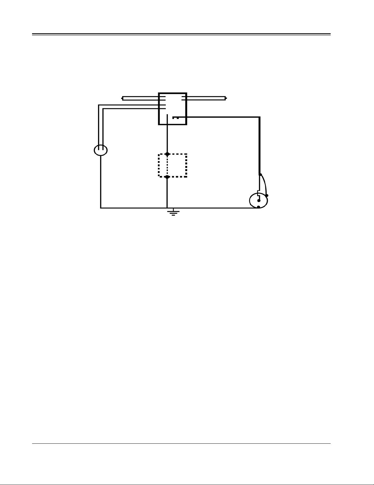
3.2 Making Circuit Connections
Connections should be made in the order as listed below and as shown in
Figure 3-1.
3.2.1 Vehicle Ground. If using a vehicle mounted PFL40A, ensure the
3.2.2 PFL Chassis Ground. If using a vehicle mounted PFL40A, use the
AVTMPFL40A-EN Rev C June 2008
than 100 milliohms to earth.
Vehicle Ground Terminal has less than 100 milliohm impedance to the
local station earth ground.
Megger supplied Safety Ground Cable to connect the PFL40A Chassis
Ground Terminal directly to the Vehicle Ground Terminal. If using a
portable PFL40A, use the Megger supplied Safety Ground Cable to
connect the PFL40A Chassis Ground Terminal directly to local station
earth ground. In all cases, take great care to ensure that the ground cable
connection is as short as possible. If your system is equipped with the
optional Safety Ground Monitor circuit, then at this time, connect the
7

M
External Ground Monitor probe between the PFL and an alternate local
station earth ground (outside the vehicle, if used).
3.2.3 Input Power Source Ground. If using a Vehicle Mounted PFL, ensure
the Input Power Source Ground Terminal is less than 100 milliohms
impedance to the Vehicle Ground Terminal. If using a portable PFL,
ensure the Input Power Source Ground Terminal is less than 100
milliohms of impedance to Local Station Earth Ground.
3.2.4 Cable Specimen Concentric Neutral. Ensure the Cable Specimen
concentric neutral has less than 100 milliohm impedance to Local Station
Earth Ground.
3.2.5 De-energize the PFL HV Cable and Cable Specimen, prior to
testing (Temporary connection). NEVER assume that either the PFL
High-Voltage Output cable or the Cable Specimen is completely
discharged. After ensuring an adequate Ground system (as above) and
before making any connections, the PFL40A High-Voltage output cable
and Cable specimen’s High Voltage conductor should be de-energized by
temporarily grounding each (to Local Station Earth Ground) with a
Safety Ground Stick (not supplied). Be sure that any stored energy is
completely discharged before continuing. Once de-energized, and while
wearing rated rubber gloves, connect a temporary Safety Ground Jumper
cable between the cable specimen’s high voltage conductor and its
concentric neutral.
3.2.6 Interlock circuit. User must provide a closed electrical circuit path
across pins B/E of the interlock jack before the PFL40A will function
properly. The connection should be made with the mating plug
(supplied) using a two-wire twisted pair, 18 gauge or larger, 300 V
insulated cable. Megger recommends the User remove the shorting wire
from the plug and run the circuit through a suitable test area interlock
system. In the event the interlock loop is opened, the test is automatically
terminated. When the optional external Decay Module is used, plug the
interlock into the Decay Module interlock cable jack and then connect
the Decay Module interlock plug into the normal PFL40A interlock
connector.
3.2.7 External Warning Beacon. The User is provided access to an electrical
circuit path, which closes only when the High Voltage Output is
energized. To utilize this path, using a two-wire twisted pair, 18 gauge or
larger and 600 V insulated cable, connect an external high voltage
warning beacon circuit across the provided pins A and B on the External
Beacon plug. The circuit can handle 3 A, 250 VAC, 60 W, 125 VA.
3.2.8 Surge Return. Only after the PFL40A has been properly grounded,
connect the high voltage output cable to the PFL40A. Then connect the
Surge Return Terminal (thin, black lead terminated with a Vise Grip™
style clamp) to the cable specimen concentric neutral.
AVTMPFL40A-EN Rev C June 2008
8

PREPARING FOR TEST
Do not allow any other conductors (if bundled) to “float” during test.
Connect all such conductors, if any, to the cable neutral, making firm,
short connections.
The Surge Return is the path that is designed to safely return the Surge
Current directly back to the Surge Capacitor through the coaxial shield of
the PFL high voltage output cable.
WARNING
THE SURGE RETURN IS ISOLATED FROM CHASSIS GROUND BY A 2000
OHM RESISTOR. THIS LIMITS CURRENT IN THE CASE OF A FAILED
CONCENTRIC NEUTRAL. THE SURGE RETURN CANNOT BE USED AS A
SUBSTITUTE SYSTEM GROUND.
SAFETY GROUND MUST BE CONNECTED TO THE LOCAL STATION EARTH
GROUND. THE IMPEDANCE OF THE LOCAL STATION EARTH GROUND
MUST BE VERIFIED AS HAVING AN IMPEDANCE OF LESS THAN 100
MILLIOHM TO GROUND. THE CONNECTION FROM THE STATION GROUND
TO THE SPECIMEN CONCENTRIC NEUTRAL MUST BE VERIFIED AS HAVING
LESS THAN 100 MILLIOHM OF IMPEDANCE.
FAILURE TO FOLLOW THIS PROCEDURE CAN RESULT IN THE DEATH OF
THE OPERATOR AND/OR THE DESTRUCTION OF THE EQUIPMENT.
The operator is isolated from transient voltages along the surge return by the
insulation system in the PFL and by the insulated jacket of the high voltage
output cable. Tears or breaks in the insulating jacket of the High-Voltage output
cable expose the Surge Return to the operator and poses a safety hazard and the
cable should be replaced.
DO NOT EXTEND the Surge Return lead of the HV Output Cable must not
be extended because this introduces excessive impedance in the Surge Return
and could result in exposed hazardous voltages.
3.2.9 High-Voltage Output Cable – Core Conductor. Once the Surge
Return connection is made as per section 3.2.8, then connect the HighVoltage Output Terminal (white lead with a red band terminated with a
Vise Grip™ style clamp) to the high voltage conductor of the cable
specimen. Be sure that the exposed conductor and clamp are sufficiently
insulated to withstand the test voltage.
3.2.10 Connect the Input Power Cord. Before making this connection,
Ensure the Input Power Source meets the requirements as listed in
Section 3.2.2 and Specifications Section 8. Also make sure that the
ON/OFF switch (Figure 1-1, No. 1) is in the OFF position. Connect the
input power cable to the PFL40A first, then to the power source.
3.2.11 Remove the Safety Ground Jumper cable. Once all of the above
connections are made, and while wearing rated rubber gloves, remove the
AVTMPFL40A-EN Rev C June 2008
9
M
temporary safety ground jumper cable (applied in Section 3.2.5.) between
the cable specimen’s high voltage conductor and its concentric neutral.
The system is now ready to begin testing.
PFL40A
Beacon Circuit
Input Power
110-130VAC /
220-265VAC
50/60 Hz
100 milliohms max
Figure 3-1 PFL40A Connection Diagram
Interlock Circuit
High-Voltage Output Cable
Safety Ground Cable (supplied)
100 milliohms max
Van (if used) Surge Return
100 milliohms max
100 milliohms max
Local Station
Earth Ground
Cable
Specimen
10
AVTMPFL40A-EN Rev C June 2008

4
p
3
2
CABLE TESTING
4.1 Main Menu Operation
The PFL system provides the User with up to six separate test or specimen
conditioning modes:
Arc Reflection
Impulse Current (surge, IC)
Pulse Echo (Time Domain Reflectometer, TDR)
Cable Burn Down
Dielectric Withstand (Proof)
Decay
To select any of the options listed, press the Up/Down arrows until
the Selection Arrow (corresponding to the desired Option) begins to flash.
Then press the Right Arrow button to activate the desired option.
PLEASE SELECT A MODE
ARC REFLECTION
SURGE (IC)
PULSE ECHO (TDR)
CABLE BURN DOWN
PROOF (0-40KV)
DECAY
LANGUAGE
ESC
Figure 4 1: Main Control Menu
Press to Activate the
Selected Option
Flashing arrow
indicates Selected
O
tion
Press to Select
1
Option
AVTMPFL40A-EN Rev C June 2008
11

M
4.2 Typical Fault Location Strategy
4.2.1 The most important aspect of locating a cable fault is the development of
a strategy that will allow the fault location to be safely and positively
identified. The following steps illustrate a typical approach to finding a
fault.
1. Deploy equipment, making sure that all company and equipment
manufacturers’ safety guidelines are followed.
2. Positively identify the faulted cable. If this has not been
accomplished by network diagnostics, isolate all of the suspect circuit
elements and use the TDR to determine if all of the elements appear
to have the same electrical length and the same features (splices,
transformers, etc., etc.) at approximately the same distance. (Please
see the MTDR operating instructions in Addendum A).
3. If all circuit elements appear to be equal, determine if the electrical
length of the circuit elements is in agreement with the known
physical length of the circuit. If it does not agree, adjust the TDR
propagation velocity accordingly. (Please see the MTDR operating
instructions in Addendum A for the propagation velocity adjustment
procedure).
4. If the MTDR data is inconclusive, use either the Dielectric Test or
Cable Burn Down function to positively identify the faulted phase.
Bring each phase up to test voltage individually. Note the breakdown
voltage when the faulted phase is found.
5. After the faulted phase has been identified, begin pre-location by
engaging the Arc Reflection Test (Please see section 4.3) mode and
configuring the MTDR for Arc Reflection Testing. Start testing at the
breakdown voltage noted during the previous step. Increase the test
voltage slowly. Note that the longer the cable is, the greater the cable
capacitance. The Arc Reflection breakdown voltage will be
significantly higher than the breakdown voltage observed during step
4 when dealing with very long cables due to capacitive voltage
division. If the fault signature seems to be unstable, increase the
discharge voltage slightly.
6. If the fault does not consistently breakdown at the maximum
allowable voltage, select the Cable Burn Down function. Raise the
voltage to either the maximum allowable voltage or until the fault
breaks down in a relatively consistent manner as indicated by
relatively stable current and voltage. Let the Cable Burn Down
function operate until the discharge current is stable. After a few
minutes of stable discharge, return to Arc Reflection.
7. Once the fault location has been pre-located by using the Arc
Reflection test, the fault can be pinpointed either by acoustic or
electroacoustic methods. Set the PFL to Impulse Current and set the
discharge voltage to the final voltage noted in step 5. Set the
AVTMPFL40A-EN Rev C June 2008
12
 Loading...