

Page 1

AVTMPFL22M
Rev 1
April 2011
User Guide
PFL22M1500
PFL22M1500INV
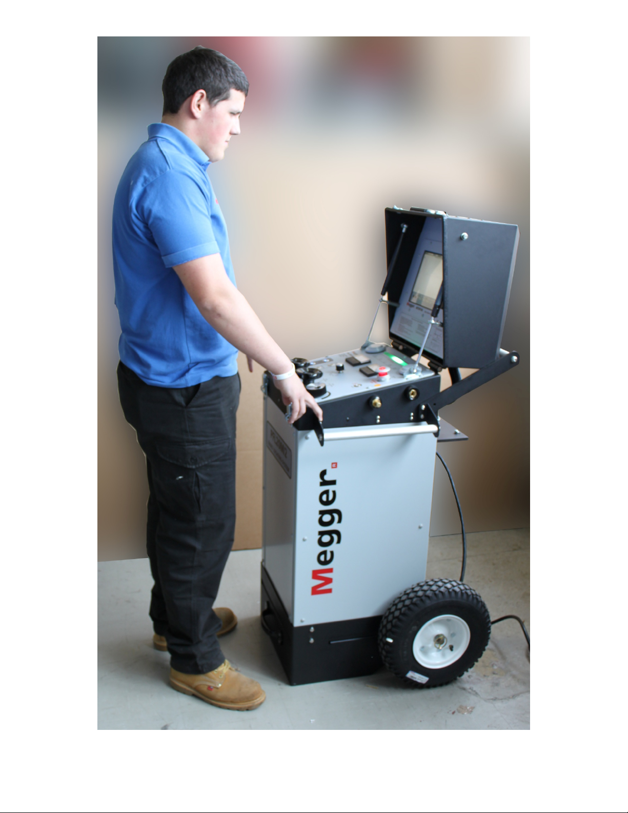
Megger Portable Cable Fault Locator
HIGH VOLTAGE EQUIPMENT
Read this entire manual before operating.
M
Valley Forge Corporate Center
2621 Van Buren Avenue
Norristown, PA 19403-2329
U.S.A.
610-676-8500
www.megger.com
Page 2
Page 3

PFL22M1500-XX
PFL22M1500INV-XX
(XX is used to indicate Language specific model)
Megger Portable Cable Fault Locator
Page 4

Copyright© 2011 by Megger. All rights reserved.
The information presented in this manual is believed to be adequate for the intended use of the product.
The products described herein should not be used for purposes other than as specified herein.
Specifications are subject to change without notice.
Page 5

WARRANTY
Products supplied by Megger are warranted against defects in material and workmanship for a period of one
year following shipment. Our liability is specifically limited to replacing or repairing, at our option, defective
equipment. Equipment returned for repair must be shipped prepaid and insured. Contact your local
MEGGER representative for instructions and a return authorization (RA) number. Please indicate all
pertinent information, including problem symptoms. Also specify the serial number and the catalog number
of the unit. This warranty does not include batteries, lamps or other expendable items, where the original
manufacturer’s warranty shall apply. We make no other warranty. The warranty is void in the event of abuse
(failure to follow recommended operating procedures) or failure by the customer to perform specific
maintenance as indicated in this manual.
Local Megger Offices
Australia Canada France
Megger Pty Limited
Unit 1, 11-21 Underwood Road
Homebush
NSW 2140
T: +61 (0)2 9397 5900
F:+61 (0)2 9397 5911
Germany India Kingdom of Bahrain
Megger GmbH
Obere Zeil 2
61440 Oberursel
Deutschland
T: 06171-92987-0
F: 06171-92987-19
Kingdom of Saudi Arabia South Africa Sweden
PO Box 1168
Khobar 31952
T: +966 3889 4407
F: +966 3889 4077
mesales@megger.com
Switzerland United Kingdom (Dover)
Megger Schweiz AG
Ob. Haselweg 630
5727 Oberkulm
Aargau
T: +41 62 768 20 30
F: +41 62 768 20 33
United States
(Dallas)
4271 Bronze Way,
Dallas, Texas 75237-1019 USA
T: 1-800-723-2861
F: 1-214-331-7399
110 Milner Avenue Unit 1
Scarborough Ontario
M1S 3R2 Canada
T: 1 416 298 6770
F: 416 298 0848
Megger (India) Pvt Limited
501 Crystal Paradise Mall
Off. Veera Desai Road
Andheri (W)
Mumbai 400053
T: +91 22 26740468
F: +91 22 26740465
PO Box 22300
Glen Ashley 4022
Durban
South Africa
T: +27 (031) 5646578
F:+27 (031) 5637990
Megger Limited
Archcliffe Road
Dover CT17 9EN
T: 01304 502101
F: 01304 207342
United States
(Valley Forge)
Valley Forge Corporate Centre
2621 Van Buren Avenue
Norristown, PA 19403 USA
T: 610 676 8500
F: 610-676-8610
23 rue Eugène Henaff
ZA du Buisson de la Couldre
78190 TRAPPES
T: 01 30 16 08 90
F: 01 34 61 23 77
P.O. Box 15777
Office 81, Building 298
Road 3306, Block 333
Manama
Kingdom of Bahrain.
T: +973 177 40 620
F: + 973 177 20 975
mesales@megger.com
Megger Sweden AB
Eldarvägen 4
Box 2970
SE-187 29 TÄBY
SWEDEN
T: +46 8 510 195 00
F: +46 8 510 195 95
United States
(College Station)
4064 State Highway 6 South
College Station, TX 77845 USA
T: 979-690-7925
F: 979-690-0276
Page 6

Safety
H
Voltages of greater than 50 V applied across dry unbroken human skin are capable of
producing heart fibrillation if they produce electric currents in body tissues which
happen to pass through the chest area.[citation needed] The electrocution danger is
mostly determined by the low conductivity of dry human skin. If skin is wet, or if
there are wounds, or if the voltage is applied to electrodes which penetrate the skin,
then even voltage sources below 40 V can be lethal if contacted. Additionally
research has shown that where the skin has been compromised, very small voltage of
up to 3V can kill.
Accidental contact with high voltage supplying sufficient energy will usually result in
severe injury or death. This can occur as a person's body provides a path for current
flow causing tissue damage and heart failure. Other injuries can include burns from
the arc generated by the accidental contact. These can be especially dangerous if the
victim's airways are affected. Injuries may also be suffered as a result of the physical
forces exerted as people may fall from height or be thrown a considerable distance.
Low-energy exposure to high voltage may be harmless, such as the spark produced
in a dry climate when touching a doorknob after walking across a carpeted floor.
Page 7

Table of Contents
1 SPECIFICATIONS ............................................................................................................................... 1
Supply .............................................................................................................................................. 1
Input Voltage source ..................................................................................................................... 1
High Voltage .................................................................................................................................. 1
Proof / Burn Output .................................................................................................................... 1
Surge Impulse (Voltage Impulse) ............................................................................................... 2
Arc Reflection & Arc Reflection Plus ........................................................................................ 2
Modes of Operation ...................................................................................................................... 2
Low Voltage ................................................................................................................................... 2
MTDR 100 (Time Domain Reflectometer) ............................................................................... 2
Metering .......................................................................................................................................... 3
Environmental ............................................................................................................................... 3
Dimensions & Weights ................................................................................................................. 4
Accessories ..................................................................................................................................... 4
Standard (supplied with instrument) ........................................................................................... 4
Optional (not supplied as standard) .......................................................................................... 5
2 GETTING TO KNOW YOUR PLF22M ......................................................................................... 7
Top Panel Controls ....................................................................................................................... 7
Safety ............................................................................................................................................... 7
Metering .......................................................................................................................................... 9
Controls ........................................................................................................................................ 10
External Connections ................................................................................................................. 12
External Connections ................................................................................................................. 13
Integrated MTDR ........................................................................................................................ 14
3 SAFETY ................................................................................................................................................ 15
General Safety Precautions ........................................................................................................ 15
Safety in Using the PFL .............................................................................................................. 17
4 PREPARING FOR TEST .................................................................................................................. 19
Important Safety Warnings ........................................................................................................ 19
Site Preparation ............................................................................................................................ 20
Making Connections ................................................................................................................... 20
Earth (Ground) the Instrument ................................................................................................ 20
Incoming Supply Lead/Cord ..................................................................................................... 21
HV Interlock blanking plug ....................................................................................................... 21
Connection HV Cable ................................................................................................................ 21
Sheath / Concentric connection ............................................................................................... 21
High Voltage Cable connection ................................................................................................ 21
Safety Zone ................................................................................................................................... 21
Switching On ................................................................................................................................ 22
Connection Diagram ................................................................................................................... 22
AVTMPFL22M Rev 1 April 2011
i
Page 8

M
5 OPERATION OF THE PFL22M 23
Test Modes ................................................................................................................................... 23
Connections ................................................................................................................................. 23
Switching on the Unit ................................................................................................................. 24
Test Procedures ........................................................................................................................... 24
D.C. Dielectric withstand (Proof) Test .................................................................................... 24
D.C. Dielectric Proof/Burn ....................................................................................................... 25
Arc Reflection : High Voltage Prelocation .............................................................................. 26
Impulse Current (Surge Impulse, I.C.E.) : High Voltage Prelocation ................................. 28
Surge Generation (Surge Impulse): High Voltage Pinpoint Location ................................. 29
6 MAINTENANCE ............................................................................................................................... 31
ADDENDUM 1 MTDR100 User Guide ............................................................................................. 33
Getting to know your MTDR100 ............................................................................................. 35
MTDR100 Specification ............................................................................................................. 36
Modes of Operation .................................................................................................................... 36
Overview of Methods available on the PFL22M1500 ........................................................... 37
TDR / Pulse Reflection .............................................................................................................. 37
Arc Reflection .............................................................................................................................. 37
Arc Reflection Plus...................................................................................................................... 37
Differential Arc Reflection (DART) ......................................................................................... 37
Impulse Current (ICE or Current Impulse) ............................................................................ 37
Display .......................................................................................................................................... 38
Status Bar ...................................................................................................................................... 38
Operator Menu Bar ..................................................................................................................... 39
Single Button Operation ............................................................................................................. 40
Rotary Jog-Dial (item 35) ........................................................................................................... 40
Operation of the MTDR100/300 ............................................................................................. 41
Enabling the MTDR (When Integrated with PFL system) .................................................. 41
Initial Set-up ................................................................................................................................. 41
ADDENDUM 2 ....................................................................................................................................... 51
Specification ................................................................................................................................. 53
Protection ..................................................................................................................................... 54
Operation ...................................................................................................................................... 56
Determine Battery Capacity ....................................................................................................... 56
Connect the Battery Cables ........................................................................................................ 56
Cabling Guidelines ...................................................................................................................... 56
ADDENDUM 3 ....................................................................................................................................... 59
Cable Fault Location Applications Guide ............................................................................... 59
Typical Fault Locating Strategy ................................................................................................. 61
Overview of Fault Prelocation Methods .................................................................................. 63
Description of TDR or Pulse Echo techniques ...................................................................... 63
Description of Arc Reflection ................................................................................................... 64
Description of Impulse Current ................................................................................................ 65
Description of Voltage Decay ................................................................................................... 66
AVTMPFL22M Rev 1 April 2011
ii
Page 9

UPON RECEIPT OF YOUR DELIVERY
Prior to operation, check for loosened hardware or damage incurred during
transit. If these conditions are found, a safety hazard is likely, DO NOT attempt
to operate equipment.
Please contact Megger as soon as possible.
Please check your delivery against:
a) your order
b) our advice note
c) the item delivered, and
d) the parts list
any shortages must be reported immediately.
AVTMPFL22M Rev 1 April 2011
iii
Page 10

M
STANDARD MANUAL CONVENTIONS
This manual uses the following conventions:
Bold indicates emphasis or a heading.
NOTE:
F
G
is used to set off important information from the rest of the text.
A WARNING symbol alerts you to a hazard that may
result in equipment damage, personal injury, or death.
Carefully read the instructions provided and follow all
safety precautions.
A CAUTION symbol alerts you that the system may not
operate as expected if instructions are not followed.
AVTMPFL22M Rev 1 April 2011
iv
Page 11

1
SPECIFICATIONS
Supply
Input Voltage source
PFL22M1500-XX is fitted with automatic voltage switching and as such can
be supplied from either, a) 108 to 135Volts or b) 208 to 265Volts supplies.
The PFL22M1500-XX, maximum power requirement is 1500 VA when used
with AC input. Two-pole three-terminal grounding type connector must be
used.
The PFL22M1500INV-XX has a 12V inverter installed allowing operation
from a suitable 12V Supply, connected to the auxiliary connection on the
side of the unit.
The PFL22M1500INV-XX maximum power requirement of a 12V.d.c.
power source is 1900 VA (160A), when used with the authorized inverter
unit.
High Voltage
Proof / Burn Output
Output voltage 0 to 10kV dc negative wrt earth
Proof Current 0 to 115mA (10V range)
Burn Current 0 to 115mA (10V range)
AVTMPFL22M Rev 1 April 2011
0 to 20kV dc negative wrt earth
0 to 55mA (20kV range)
0 to 55mA (20kV range)
1
Page 12

M
Surge Impulse (Voltage Impulse)
Ranges Two (2)
Impulse voltage 0 to 8kV
0 to 16kV
Impulse Energy
@ 100% of range
Impulse Repetition Rate
Single Shot
Arc Reflection & Arc Reflection Plus
Voltage
Energy @ 100% of range
Traces:
Modes of Operation
1500joule @ 0 to 8kV
1500joule @ 0 to 16kV
5 to 30seconds
0 to
8kV
0 to 16kV
1500joule @ 0 to 8kV
1500joule @ 0 to 6kV
1024 to 16 (Dependent on range
selected)
Low Voltage
High Voltage
Pulse Echo ; Direct; Comparison
Arc Reflection , Arc Reflection Plus (ARP),
Differential Arc Reflection (DART) , Impulse Current
Low Voltage
MTDR 100 (Time Domain Reflectometer)
Operation
Modes
Ranges
Single Jog-Dial
Pulse Echo, Direct, Comparison,
Arc Reflection, Arc Reflection Plus (ARP),
Differential Arc Reflection (DART) Impulse Current
10 ranges:
100m, to 55km ; 328ft to 180,445ft
2
AVTMPFL22M Rev 1 April 2011
Page 13

SPECIFICATIONS
Pulse Width
Pulse Amplitude
Sampling Rate
Resolution (VP=55%)
Timebase accuracy
Output impedance
Gain
Display
Storage
Metering
Voltmeter
50ns, 100ns, 200ns, 500ns 1μs, 2 μs, 5 μs, 10 μs
25V into 50 Ohms
100Megasamples/sec
0.82m / 2.7ft
200 ppm
50 Ohms
Variable over 60dB in 5dB steps
XGA 1024 x 768 26.5mm (10.4”)
On-board and USB
Analogue 0 to 20kV
Accuracy 5%
Ammeter
Environmental
Operating Temp
Storage Temperature
Humidity
Elevation
Analogue 0 to 300mA
Accuracy 5%
-20 to 50o C / -4 to 120 oF
-30 to 55o C / -22 to 131oF
5 to 95% RH non-condensing (operating)
1600m (De-rate voltages at higher altitudes)
AVTMPFL22M Rev 1 April 2011
3
Page 14

M
Dimensions & Weights
Height
Width
Depth
965 mm / 38 inch
536 mm / 21inch
503 mm / 20 inch
Weight (Total) 131kgs / 290lbs
Accessories
Standard (supplied with instrument)
High Voltage Cable
Safety Ground Cable
Input/supply Cable
15m flexible, lightweight,40kV single
core HV cable
15m flexible ground cable with
ferrules,
line cord/ supply cable (1 x ea)
1001-123:
19265-15:
17032-4 ; North American
17032-5 ; International
Shorting plug
Cable Bag/Satchel
Documentation
Software
17032-12; BS
170032-13; EU SHUKO
Interlock shorting plug qty 1 supplied 10226-1
Cable bag to take all cables 2001-813:
User Guide AVTMPFL22:
Cable Analysis Software CAS01:
4
AVTMPFL22M Rev 1 April 2011
Page 15

Optional (not supplied as standard)
SPECIFICATIONS
HV Vice Groups
PFL22M Transit Case
HV Discharge stick
12 V External Battery
Discharge Receiver:
Cable Drums
Adjustable HV Vice
18944-2
Grips
Transit Case 2001-289
70kV Discharge stick 222070-62
12V/92Ah Battery 1001-690
Acoustic and
MPP2000 or MPP1001
Electromagnetic
pinpoint receiver
Megger have several cable drums and cable drum
assemblies which need to be specified dependent on
installation and possible combination with other
instruments. Another consideration is where the
equipment is installed into a vehicle or trailer the
available payload must be taken into consideration.
It is recommend that the factory is contacted prior to
ordering the optional cable drums or cable drum
assemblies
AVTMPFL22M Rev 1 April 2011
5
Page 16

M
M
6
AVTMPFL22M Rev 1 April 2011
Page 17
2
GETTING TO KNOW YOUR PLF22M
Top Panel Controls
Safety
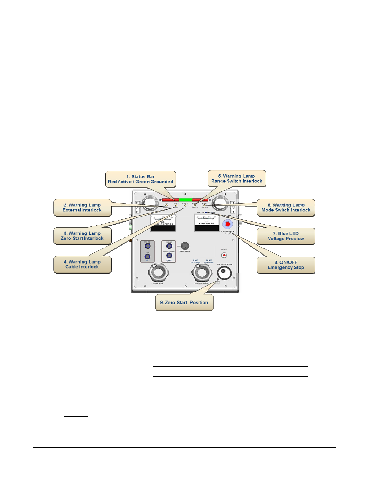
1. Status Bar: Indicates
HV On / HV Off
2. External Interlock LED
(Yellow): Indicates if
External Interlock
activated
AVTMPFL22M Rev 1 April 2011
High visibility status bar Indicates Operating status of the
PFL22.
Ungrounded / HV On: Two outer segments glow Red
indicating earth/ground off and HV active.
Note: HV not active in TDR mode
Grounded / HV Off: Single inner segment glows Green
indicating Earths are on with no HV present.
When illuminated indicates that the optional external
interlock has been activated, or interlock blanking-plug
not in place.
7
Page 18

M
3. Zero Start Interlock
LED (Yellow)
of voltage control not at
: Indicates
zero
4. HV Cable Interlock
LED (Yellow): Indicates
HV Cable not connected
5. Range Switch Interlock
LED (Yellow): Indicates
if Range Switch not seated
6. Mode Switch Interlock
LED (Yellow): Indicates
if Mode Switch not seated
7. Voltage Preview
LED (Blue): Preview of
voltage to be applied
When illuminated indicates that the voltage control knob
is not at zero, Voltage control must be at zero before
commencing any voltage changes. Only active for dc
operations.
When illuminated indicates that the HV cable connection
to the PFL has not been made correctly.
Illuminates if the Range switch is not properly seated,
and a range correctly selected.
Illuminates if the Mode selector switch is not properly
seated, and a mode correctly selected.
When illuminated this indicates that the voltage shown
on the Kilovolt meter is a preview only, prior to it being
applied to the cable under test. (No HV activated)
8. Emergency Stop This switch acts as an Emergency Stop and also an
On/Off switch. To disengage and turn on the instrument
pull this switch. To turn off either in an emergency or
when operation complete depress.
9. Zero Start
Voltage control must be at zero before commencing any
voltage changes. Only active for dc operations.
8
AVTMPFL22M Rev 1 April 2011
Page 19
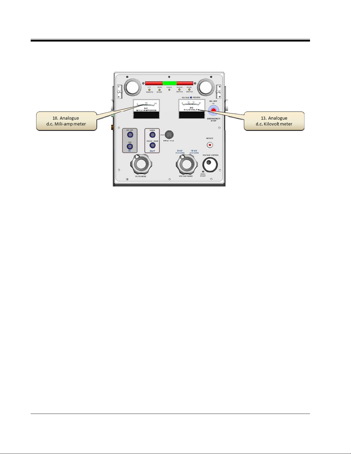
Metering
GETTING TO KNOW YOUR PLF22M
10. Milliampmeter:
0 to 300mA analogue Mili-Amp meter. Indicates the
charging current being applied (leakage current).
11. NOT USED
12. NOT USED
13. d.c. KiloVolt meter: 0 to 20 kV analogue kilovolt meter. Indicates applied
voltage (or voltage preview) in Proof/Burn, Surge, Arc
Reflection modes.
AVTMPFL22M Rev 1 April 2011
9
Page 20
M
Controls
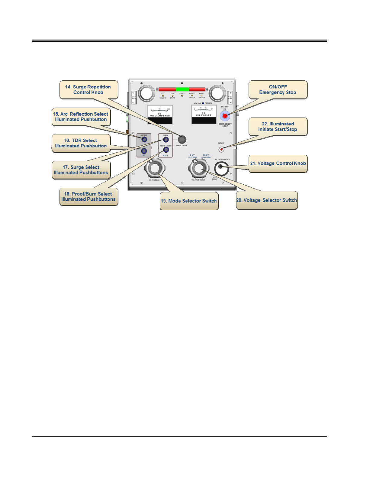
14. Surge Repetition Control Knob: Select either single shot or set the desired surge
repetition rate.
15. Arc Reflection Mode Pushbutton
(switch/indicator):
To selected Arc Reflection mode depress the push
button switch. Switch will illuminate when Arc
Reflection mode selected and active.
16. TDR Mode Pushbutton
switch/indicator:
To select TDR (Pulse Echo) depress the push
button switch. Switch will illuminate when TDR
mode selected and active.
17. Surge Mode Pushbutton
(switch/indicator):
To select Surge or Impulse Current depress the
switch. Switch will illuminate when Surge mode
selected and active.
18. Proof/Burn Mode Pushbutton
(switch/indicator):
To select Proof/Burn depress the switch. Switch
will illuminate when Proof/Burn mode selected
and active.
19. Mode Switch (Filter in/Filter out): Two position rotary selector switch, switch
between the modes that require the arc reflection
filter engaged; Arc Reflection & TDR and the
modes whereby the needs to be disengaged Surge
& Proof/Burn.
10
AVTMPFL22M Rev 1 April 2011
Page 21

GETTING TO KNOW YOUR PLF22M
20. Voltage Range Switch: Two position rotary selector switch that switches
between the proof/burn ranges of 10 & 20 kV and
the surge voltage ranges of 8 & 16 kV.
21. Voltage Control Knob: Rotary Voltage control knob, controlling the
applied voltage in Proof/Burn, Surge or Arc
Reflection modes. Control is via a zero start, hence
before selecting knob must be at zero. Only active
for dc operations.
22. Initiate pushbutton: Push button whereby the HV is activated, whether
in Proof/Burn, Surge or Arc Reflection modes.
Switch is illuminated sold green when valid made
selected and flashes when HV has been engaged.
AVTMPFL22M Rev 1 April 2011
11
Page 22
M
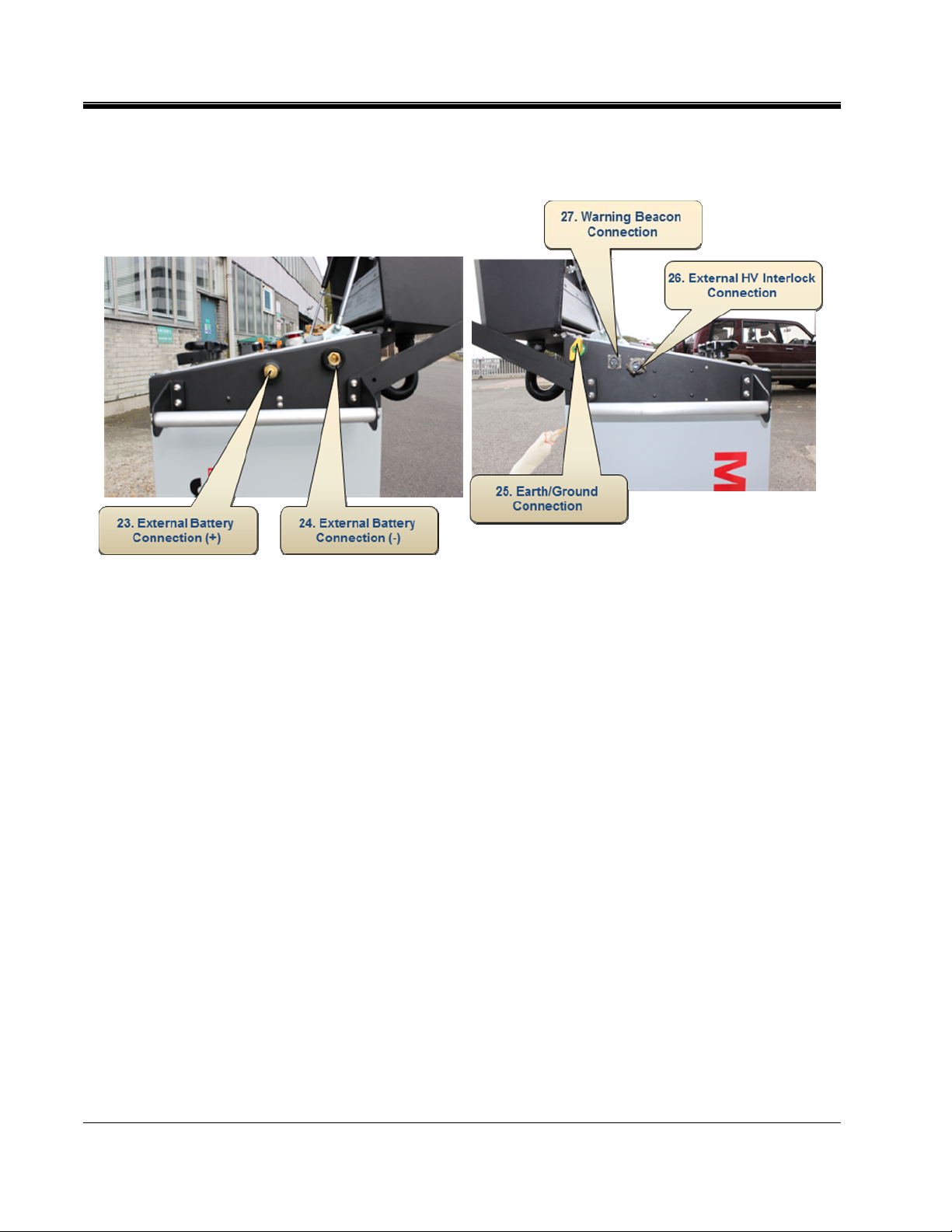
External Connections
23. External Battery connection
Positive (+):
24. External Battery connection
Negative (-):
25. Earth/Ground connection:
26. External HV interlock:
27. Warning Beacon connection:
The positive connection point when using the PFL22M
from an external 12V supply.
The negative connection point when using the PFL22M
from an external 12V supply.
Note: When external battery is used the only
earth/ground is via the external Earth/Grounding
connection (item 27)
The instrument Earthing/Grounding point. For
operator safety it is mandatory that the PFL22M is
efficiently earthed/grounded. Failure to do so could
result in serious injury or in the extreme circumstances
death.
To provide additional operator safety an external HV
interlock (optional accessory) can be fitted.
Through this connection an external warning beacon
(optional accessory) can be fitted. Connection rated at
3A, 220V dc and 250V ac, exceeding this limit will
damage the unit
12
AVTMPFL22M Rev 1 April 2011
Page 23
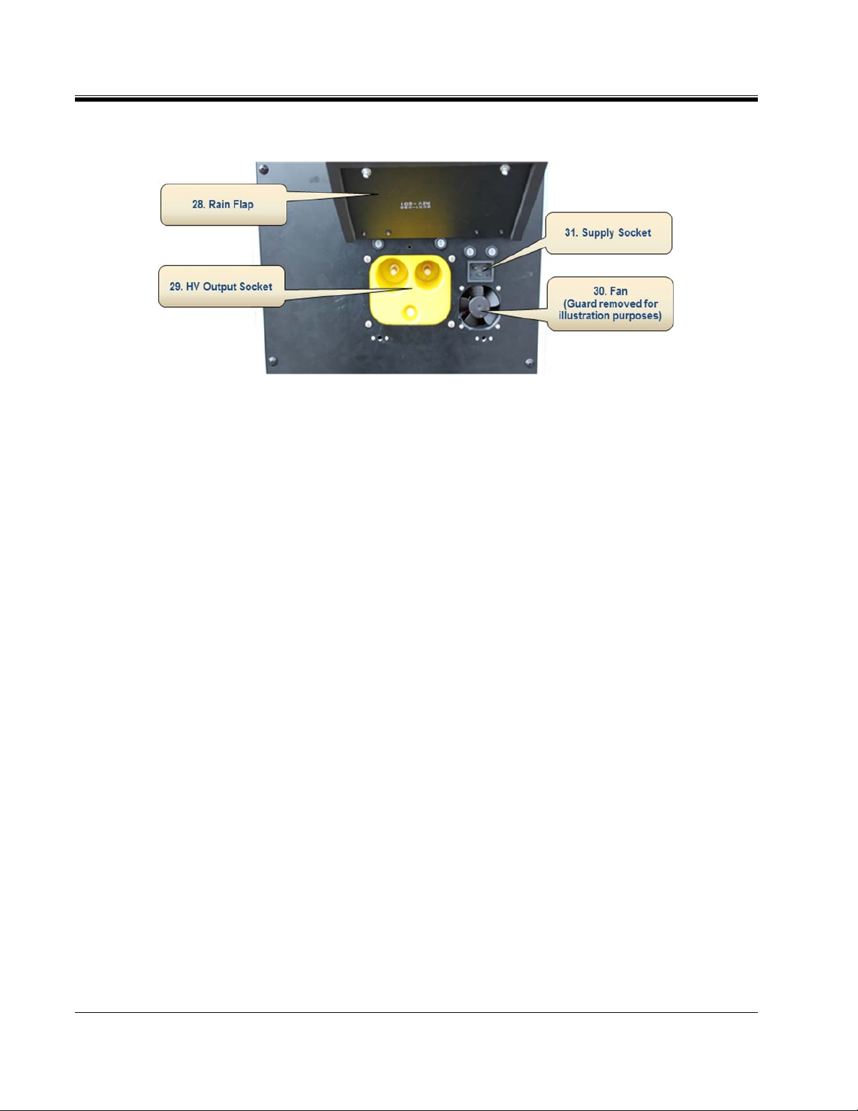
External Connections
GETTING TO KNOW YOUR PLF22M
28. Rain Flap Closed and secured during transportation to
maintain Instrument IP rating.
29. HV Output Socket
The PFL22M is supplied with a 5m detachable
40kV HV cable. Interlocks built into the
receptacle inhibit the use of the unit unless the
30. Fan
31. Supply Socket
HV cable is securely fitted.
(Guard/Cover removed for illustration purposes)
PFL22M1500 is fitted with automatic voltage
switching and as such can be supplied from either
a) 108 to 135Volts or 210 to 265Volts.
AVTMPFL22M Rev 1 April 2011
13
Page 24
M
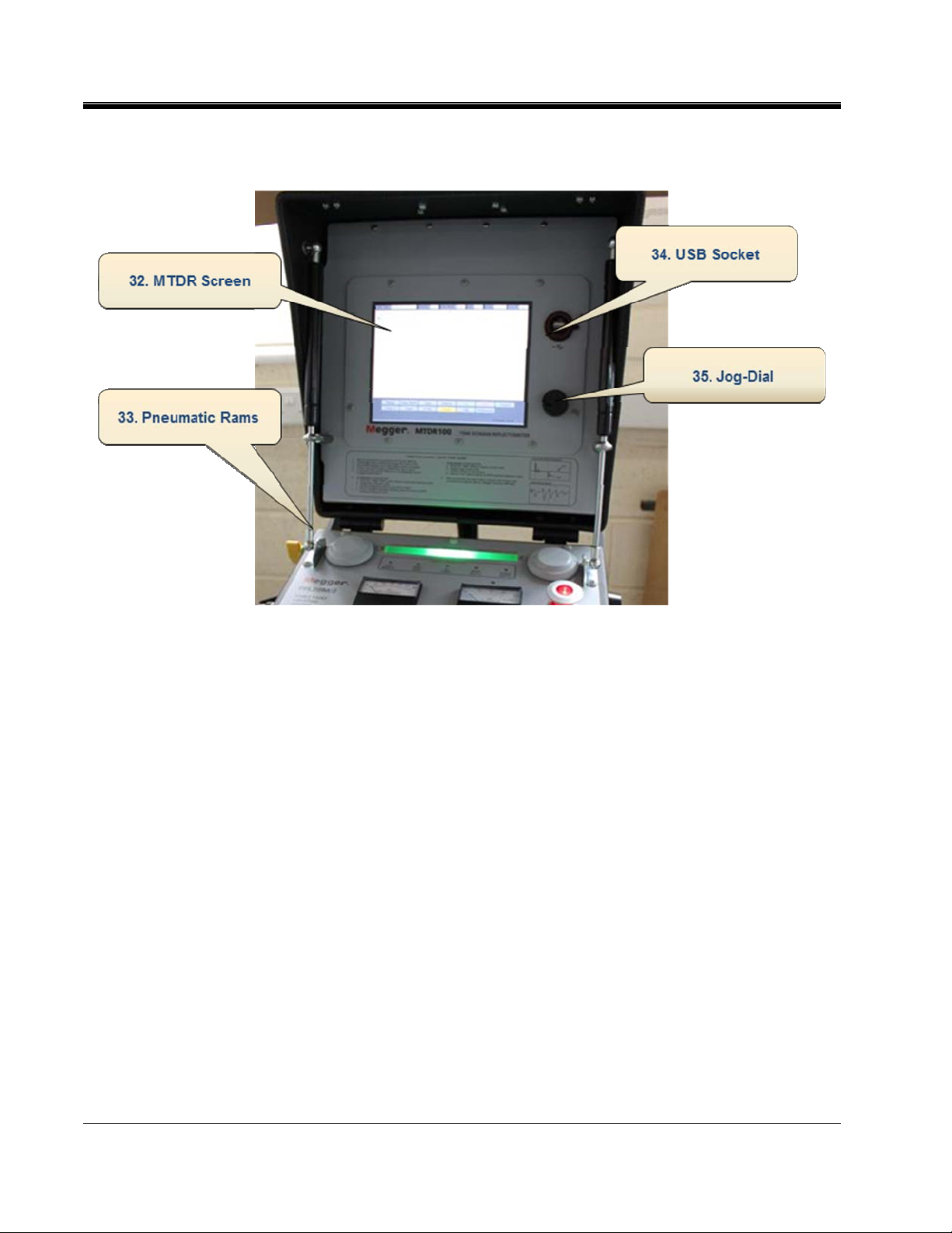
Integrated MTDR
32. MTDR Display Large 21cm (10.4”) LCD display. Displaying all parameters
and the necessary information and traces to achieve rapid
accurate fault location.
33. Pneumatic Lid
Rams:
34. USB Port:
Pneumatic support rams provide safe support whilst
opening and closing the lid of the PFL22M.
USB port to download/upload memorized traces including
all parameters.
35. MTDR Jog Dial:
One-button operation of the MTDR is achieved using the
Rotary Jog-Dial control knob. With this jog-dial the
operator sets all the preferences, selects modes of
operation and undertakes the fault analysis and fault prelocation.
14
AVTMPFL22M Rev 1 April 2011
Page 25

3
SAFETY
Safety is the responsibility of the user
General Safety Precautions
Local Operating Company Safety Standards and Instructions should always be followed,
the following are for guidance only.
The PFL22M1500 should only be used for its stated application. Any other
application may render the safety features inoperative and expose the operator to
dangerous levels of energy.
In the event of equipment malfunction, the unit should immediately be de-
energized and returned to Megger for repair.
This equipment generates High Voltages and high Current, which can be lethal.
Operators must read and understand this entire User Guide prior to operating
the equipment. Operator must follow the instructions of this User Guide and
attend the equipment while the equipment is in use.
Only “Competent” or “Authorized” personal should operate the PFL22M1500
system.
Authorized Person: means a person recognized by an Authorizing Officer as
having sufficient technical knowledge to perform certain duties in respect of
defined electrical systems and equipment. An Authorized Person is normally
appointed in writing by an Authorizing Officer.
Authorized Persons are those individuals who mange the Code and then ensure
compliance with the Rules. The limit of responsibility may in general be different
for each Authorized Person and must be detailed in writing. The level of
responsibility will depend on the ability, experience, and on the extent and nature
of the equipment under the control of the Authorized Person.
AVTMPFL22M Rev 1 April 2011
15
Page 26

M
Competent Person: means a person having:-
Adequate knowledge of electricity
Adequate experience of electrical work
An understanding of the system to be worked on and practical experience of
that class of system
An understanding of the hazards which may arise during the work, and the
precautions which need to be taken
The ability to recognise at all times whether it is safe for work to continue
Note: If persons are not competent to undertake particular work on their own,
for example those who have not completed their training, then they must
be accompanied and supervised by a competent person.
Observe all safety warnings on the equipment, and provided in this manual.
Use this equipment only for the purposes described in this manual.
Do not use the equipment in rain or snow unless in sheltered position.
Do not operate the equipment whilst standing in water.
All terminals of H.V. equipment are potential electric shock hazards. Use all
safety precautions to prevent contact with energized parts of the equipment
and related circuits.
Use suitable barriers, barricades, or warnings to keep persons not directly
involved with the work away from test activities.
Never connect the test equipment to energized cables or use in explosive
atmosphere.
Use the grounding and connection procedures recommended in this manual.
Personnel using heart pacemakers should obtain expert advice on the
possible risks before operating this equipment or being close to the
equipment during operation.
16
AVTMPFL22M Rev 1 April 2011
Page 27

Safety in Using the PFL
Never assume that either the PFL22M1500 High Voltage Output Cable or
the Cable Specimen is de-energized. Always treat exposed conductors and
connections as potential electric shock hazards.
The PFL22M1500 and the Cable under test are both sources of
instantaneously lethal levels of electrical energy.
Do not use this equipment to locate faults on any cable that may be close
enough to an energized cable to allow a burn-through of the insulation of
the energized cable.
Do not operate the PFL if it has not first been stabilized and in an upright
position.
Remain a safe distance from all parts of the High-Voltage circuit, including
all connections, unless the equipment is de-energised and all parts of the test
circuit are earthed/grounded. Be aware that any voltage applied to the Cable
Specimen will be present at the remote end(s) and at any other exposed part
of the cable, often out of sight of the operator.
SAFETY
Use the grounding and connection procedures. If other manufacturers'
equipment is used with the PFL, the user is responsible for verifying that the
grounding and interconnections between the systems comply with each
Manufacturer's Instructions.
Use Industry Accepted practices for making reliable, low-impedance
connections, capable of carrying large surge currents.
Maintain adequate air clearances between the exposed High-Voltage
conductor and any adjacent grounds to prevent spark-over. An uncontrolled
spark-over can create a safety hazard.
Megger recommends the use of appropriately rated rubber gloves when
connecting and disconnecting to the High-Voltage terminals.
An Interlock circuit is provided (and its use is highly recommended) to
enable the operator to safely control access to the complete high-voltage
circuit.
AVTMPFL22M Rev 1 April 2011
17
Page 28

M
M
18
AVTMPFL22M Rev 1 April 2011
Page 29

4
PREPARING FOR TEST
IMPORTANT SAFETY WARNINGS
The surge return is isolated from chassis ground by a 2000ohm
resistor. This limits current in the case of a failed concentric neutral.
F
F
The surge return cannot be used as a substitute system ground.
Failure to follow this procedure can result in serious injury
or in the extreme, death of the operator and/or the destruction of the
equipment.
The operator is isolated from transient voltages along the surge
return by the insulation system in the PFL and by the insulated
jacket of the high voltage output cable. Tears or breaks in the
insulating jacket of the High-Voltage output cable expose the Surge
Return to the operator and poses a safety hazard and the cable
should be replaced.
WARNING
WARNING
F
AVTMPFL22M Rev 1 April 2011
WARNING
DO NOT EXTEND the Surge Return lead of the HV Output Cable
because this introduces excessive impedance in the Surge Return
and could result in exposed hazardous voltages.
19
Page 30

M
Site Preparation
Choose a location that meets the following conditions:
The vehicle (if used) can be safely parked. Set the brakes or block the wheels.
The location is as dry as possible.
There is no flammable material stored in the vicinity.
The test area is adequately ventilated.
Both the High-Voltage conductor and the Shield of the Cable Specimen are
accessible. Be sure all equipment is de-energized. Identify the faulted cable,
obtain access to both ends, and erect safety barriers to protect the operator
from traffic hazards and to prevent intrusion by unauthorized personnel.
Beacon Warning lights are recommended.
Verify that the station ground is intact and presents an impedance of LESS
than 100 milliohms to earth/ground.
Making Connections
Before operating the PFL22M1500 the following connections and safety
procedures need to be followed.
Ensure the cable to be tested is Earthed/Grounded and de-energized.
Connect the Earthing/Grounding cable of the PFL22M1500 to a suitable
Earth/Ground point and the Earth/Ground stud on the PFL22M1500.
Connect the supply cord to the PFL22M1500 and suitable supply.
Connect the HV Interlock blanking plug (unless using external interlock).
Connect the detachable HV cable to the PFL22M1500.
Connect the Sheath of the HV cable to the cable under test.
Connect the HV connection of the HV cable to the cable under test.
Cordon off a safety zone around instrument and all exposed cable
terminations.
Earth (Ground) the Instrument
Prior to operating the PFL22M1500 or making any other connections the
instrument has to be Earthed/Grounded. This is achieved by connecting the
supplied Green & Yellow Earth /Ground lead to the Earth/Ground terminal on
the side of the instrument directly to a clean metallic Earth/Ground. If in doubt
use an Earth/Ground Tester to confirm status of Earth/Ground. It is not
sufficient just to rely on the supply earth/ground as this may not exist.
20
AVTMPFL22M Rev 1 April 2011
Page 31

Incoming Supply Lead/Cord
The appropriate (Country specific) PFL22M1500 supplied supply lead/cord
should be inserted into the receptacle at the rear of the instrument (under the
protective rain flap) and connected to a suitable stable supply in the range of a)
108 to 135Volts or b) 210 to 265Volts. Do not use extension leads, unless
suitably rated .
The maximum power consumption for the PFL22M1500 is 1500 VA when used
with AC input. Power consumption is approximately 1900 VA (160A) of 12
VDC power when used with the authorized inverter unit.
HV Interlock blanking plug
Attach the HV interlock blanking plug to the external HV interlock connection
on the right hand side of the instrument. Not required when optional HV switch
used.
Connection HV Cable
PREPARING FOR TEST
The Large Yellow HV cable termination of the HV Cable is inserted into the
HV Output socket at the rear of the PFL22M1500. Care should be taken to
ensure that the HV cable connection interlock (part of HV output socket) is
engaged. It is impossible to turn on the HV if no HV cable is connected.
Sheath / Concentric connection
Before undertaking this connection you should check to ensure that the cable
under test is Earthed/Grounded, if unable to do so it is dangerous to make any
connection to it.
The Sheath / Concentric connection of the HV Cable is connected to the
sheath/concentric connection of the cable under test with the supplied HV Clip.
High Voltage Cable connection
Before undertaking this connection you should check to ensure that the cable
under test is Earthed/Grounded, if unable to do so it is dangerous to make any
connection to it.
The HV Core connection of the HV Cable is connected to the core of the cable
under test with the supplied HV Clip.
Safety Zone
As High Voltages are present when undertaking cable testing and cable fault
location any area of potential danger needs to be cordoned off to protect people
AVTMPFL22M Rev 1 April 2011
21
Page 32

M
Switching On
Connection Diagram
from possible “electrical shock”. This includes the cable terminations, point of
connection and other areas of potential hazard.
Once all connections have been made and a safety zone established the
PFL22M1500 can be turned-on, by pulling out the emergency stop button which
also acts as an on/off switch.
During turn-on all lamps will illuminate for a short period (self check), but no
High Voltage is present or available until selected.
22
AVTMPFL22M Rev 1 April 2011
Page 33

5
OPERATION OF THE PFL22M
Test Modes
The PFL22M1500 system provides the User with the following testing and cable
fault locating modes:
D.C. Dielectric Withstand (Proof)
D.C. Proof/Burn
Pulse Echo (Time Domain Reflectometer, TDR) Low Voltage Prelocation
Arc Reflection - High Voltage Prelocation
Arc Reflection Plus (ARP) - High Voltage Prelocation
Differential Arc Reflection (DART) - High Voltage Prelocation
Impulse Current (Surge Impulse, I.C.E.) - High Voltage Prelocation
Surge Generation (Surge Impulse) - High Voltage pinpoint location
Connections
All connections shall be made and safety procedures followed as per Sections 2
and 3.
AVTMPFL22M Rev 1 April 2011
23
Page 34

M
Switching on the unit
Test Procedures
1. Turn on the PFL22M1500 by pulling out the yellow Emergency Stop button
(item 8) which also acts as an on/off switch. At turn-on all lamps will
illuminate for a short period of time, during self test.
Note: The Voltage and Mode selector switches are locked in position during
transportation to help avoid miss-handling. Therefore they cannot be
moved or turned until the unit is turned on. Additionally once a mode
has been selected these switches are locked.
2. Assuming all interlocks are satisfied the Status Bar (item 1) will glow “Green”
and all Interlock lamps will remain off. If any of the interlocks are not
satisfied the lamps will glow yellow.
D.C. Dielectric withstand (Proof) Test
The PFL22M1500 generates a dc test voltage of 0 to 20 kV negative wrt to
Earth/Ground with a current of 0 to 115 mA (10kV range) and is used to test
the integrity of cable installations. The test voltage is defined by the user and
local regulations.
1. Set the rotary Voltage Control knob (item 21) to the “Zero Start” (item 9)
position.
Note: Range and function switch cannot be moved if a mode is active.
2. Set the Voltage Range switch (item 20) to the desired range either 10 or
20kV. At this stage the Status Bar (item 1) will glow “Red”
3. Set the Mode (Filter) selector switch (item 19) to Proof-Burn & Surge. Both
lamps will illuminate, advising that either of these modes are available.
4. Depress the pushbutton of the desired mode, in this case Proof/Burn.
Selection is confirmed by the pushbutton remaining illuminated and other
pushbutton extinguishing.
Initiate button Illuminates.
5. The required test voltage is set by using the Voltage Control knob (item 21).
This voltage is displayed on the d.c KiloVolt meter (item 13) and the voltage
Preview Lamp (item 7) is illuminated indicating that the displayed voltage is a
“preview only” with no HV being applied at this time.
AVTMPFL22M Rev 1 April 2011
24
Page 35

6. Depress the Initiate button (item 22) and the selected test voltage will be
applied to the cable under test. Whilst active the pushbutton will flash.
The integrity of the cable under test can now be assessed by reviewing a)
breakdown voltage and b) leakage current.
7. To deselect, depress the Proof/Burn pushbutton (item 18), which also
engages the internal earthing/grounding and removes any High Voltage.
8. At this stage the Status Bar (item 1) will glow “Green”.
D.C. Dielectric Proof/Burn
1. Set the Voltage Control Knob (item 21) to the “Zero Start” position (item 9).
Note: Range and function switch cannot be moved if a mode is active.
2. Set the Voltage Range switch (item 20) to the desired range either 10 or
20kV. At this stage the Status Bar (item 1) will glow “Red”
OPERATION
3. Set the Mode (Filter) selector switch (item 19) to Proof-Burn & Surge group.
Both lamps will illuminate, advising that either of these modes are available.
4. Depress the pushbutton of the desired mode, in this case Proof/Burn.
Selection is confirmed by the pushbutton remaining illuminated and other
pushbutton extinguishing.
Initiate button Illuminates.
5. The required test voltage is set by using the Voltage Control knob (item 21).
This voltage is displayed on the d.c KiloVolt meter (item 13) and the Voltage
Preview Lamp (item 7) is illuminated indicating that the displayed voltage is a
“preview only” with no HV being applied at this time.
6. Depress the Initiate button (item 22) and the selected Proof/Burn voltage
will be applied to the cable under test. When active the pushbutton will flash
7. If the fault needs conditioning (burning) then the operator leaves the
proof/burn voltage applied, rather than removing it which would be the
normal practise when checking the integrity of the cable. Following a suitable
period as defined by the operator the voltage is removed.
8. To deselect, depress the Proof/Burn pushbutton (teim 18), which also
engages the internal earthing/grounding and removes any High Voltage.
9. The Status Bar (item 1) will glow “green” when all HV is removed and the
AVTMPFL22M Rev 1 April 2011
instrument and test piece has been earthed/grounded.
25
Page 36

M
Pulse Echo (Time Domain Reflectometer, TDR) : Low Voltage Prelocation
The PFL22M1500 has an integrated T.D.R.
1. Set the rotary Voltage Control Knob (item 21) to the “Zero Start” position
(item 9).
NOTE:
Range and function switch cannot be moved if a mode is active.
2. Ensure that the Voltage Range switch (item 20) is fully depressed. As we are
using TDR (low voltage prelocation) no HV voltage is required. At this stage
the Status Bar (item 1) will glow “Red”
3. Set the Mode (Filter) selector switch (item 20) to the TDR and Arc
Reflection group. Both lamps will illuminate, advising that either of these
modes are available.
4. Depress the pushbutton of the desired mode, in this case TDR. Selection is
confirmed by the pushbutton remaining illuminated and the other
pushbutton extinguishing.
5. For instructions on the use of the TDR refer to Addendum ***
MTDR100 User Guide
6. To deselect, and terminate operation depress the TDR pushbutton (item 16),
which also engages the internal earthing/grounding.
7. The Status Bar (item 1) will glow “Green”.
Arc Reflection : High Voltage Prelocation
Also Arc Reflection Plus (ARP) and Differential Arc Reflection (DART)
1. Set the rotary Voltage Control Knob (item 21) to the “Zero Start” position
(item 9).
NOTE:: Range and function switch cannot be moved if a mode is active.
2. Set the Voltage Range switch (item 20) to the desired “surge” range either 8
or 16kV. At this stage the Status Bar (item 1) will glow “Red”.
3. Set the Mode (Filter) selector switch (item 19) to the TDR and Arc
Reflection group. Both lamps will illuminate, advising that either of these
modes are available.
26
AVTMPFL22M Rev 1 April 2011
Page 37

OPERATION
4. Depress the pushbutton of the desired mode, in this case Arc Reflection.
Selection is confirmed by the pushbutton remaining illuminated and the
other pushbutton extinguishing.
5. On the MTDR select the Arc Reflection method and a standard Pulse Echo
measurement is made, with the trace being automatically stored in the
internal memory. This is your reference trace.
6. The MTDR is armed (made ready) by selecting “ARM” from the menu
buttons. The word “armed” is displayed on the MTDR.
7. For FULL instructions on the use of the TDR refer to Addendum ***
MTDR100 User Guide.
8. The required “Impulse or Surge” voltage is set by rotating the Voltage
Control knob (item 21) to the required voltage, which is normally slightly
higher than the voltage that the fault broke down at. The selected voltage is
displayed on the d.c KiloVolt meter (item 13) the Voltage Preview lamp
(item 7) is illuminated indicating that the displayed voltage is a “preview”
with no HV being applied.
9. Depress the Initiate button (item 22) and the impulse or surge voltage is
applied to the cable under test.
By observing the Voltmeter and Ammeter the operator can confirm that
there has been a full discharge.
Normally in Arc Reflection only one discharge is required; hence the Surge
Repetition Control knob (item14) is set to single shot.
10. The resultant trace on the MTDR is recorded and overlaid with the original
(reference) pulse echo trace. The point of divergence of the two traces, with
the arc reflection trace going negative of the two traces indicates the location
of the fault.
If operation “fails to trigger”, increase voltage and repeat operation
If operation fails and no point of divergence can be found, repeat operation.
NOTE The features; Arc Reflection Plus (ARP) and Differential Arc
Reflection (DART), how to configure and there benefits are contained in
the
MTDR100 User Guide .
11. To deselect depress the arc reflection pushbutton. The Status Bar (item1) will
glow “green” when all HV is removed and the instrument and test piece has
been earthed/grounded.
AVTMPFL22M Rev 1 April 2011
27
Page 38

M
Impulse Current (Surge Impulse, I.C.E.) : High Voltage Prelocation
1. Set the rotary Voltage Control Knob (item 21) to the “Zero Start” position
(item 9).
2. Set the Voltage Range switch (item 20) to the desired “surge” range either 8
or 16kV. At this stage the Status Bar (item 1) will glow “Red”.
NOTE: Range and function switch cannot be moved if a mode is active.
3. Set the Mode (Filter) selector switch (item 19) to the Surge and Proof Burn
group. Both lamps will illuminate, advising that either of these modes are
available.
4. Depress the Surge Mode pushbutton of the desired mode. Selection is
confirmed by the pushbutton remaining illuminated and the other
pushbutton extinguishing.
5. On the MTDR, select Impulse / Impulse Current.
6. The MTDR is armed (made ready) by selecting “ARM” from the menu
buttons. The word “armed” is displayed on the MTDR.
For FULL instructions on the use of the TDR refer to MTDR100 User
Guide.
7. The required “Impulse or Surge” voltage is set by rotating the Voltage
Control knob (item 21) to the required voltage, which is normally slightly
higher than the voltage that the fault broke down at. The selected voltage is
displayed on the d.c KiloVolt meter (item 13) the Voltage Preview lamp
(item 12) is illuminated indicating that the displayed voltage is a “preview”
with no HV being applied.
8. Set the Surge Repetition control (item 14) to the desired repetition rate from
3secs to 30sec.
9. Depress the Initiate button (item 22) and the impulse or surge voltage is
applied to the cable under test, and the resultant waveform on the MTDR
can be analysed to determine the fault position.
Note: By observing the Voltmeter and Ammeter the operator can confirm that there has
been a full discharge.
If operation “fails to trigger”, increase voltage and repeat operation.
To deselect depress the Surge pushbutton (item 17), which also engages the
internal earthing/grounding and removes any High Voltage.
The Status Bar (item 1) will glow “green” when all HV removed and the
instrument and test piece has been earthed/grounded.
28
AVTMPFL22M Rev 1 April 2011
Page 39

Surge Generation (Surge Impulse): High Voltage pinpoint location
1. Set the rotary Voltage Control knob (item 21) to the “Zero Start” position
item 9).
2. Set the Voltage Range switch (item 20) to the desired “surge” range either 8
or 16kV. At this stage the Status Bar (item 1) will glow “Red”.
OPERATION
NOTE:
Range and function switch cannot be moved if a mode is active.
3. Set the Mode (Filter) selector switch (item 19) to the Surge and Proof Burn
group. Both lamps will illuminate, advising that either of these modes are
available.
4. Depress the Surge Mode pushbutton (item 17). Selection is confirmed by the
pushbutton remaining illuminated and the other pushbutton extinguishing.
5. Set the Surge Repetition Control (item14) to the desired repetition rate from
3secs to 30sec. The rate selected is decided by the operator based on
conditions i.e. external noise and ease of hearing the discharges via the
ground microphone.
6. Select the required voltage using the rotary Voltage Control knob (item 21).
The selected voltage being displayed on the d.c KiloVolt meter (item 13) the
Voltage Preview lamp (item 7) is illuminated indicating that the displayed
voltage is a “preview” with no HV being applied.
7. Depress the Initiate button (item 22) and the selected impulse voltage is
applied to the cable under test at the required rate as set by the surge cycle
control.
The fault is then located using the acoustic method and a suitable impulse
receiver (MPP2000).
8. To deselect depress the Surge Mode pushbutton (item 17), which also
9. The Status Bar (item1) will glow “green” when all HV removed and the
AVTMPFL22M Rev 1 April 2011
engages the internal earthing/grounding and removes any High Voltage.
instrument and test piece has been earthed/grounded.
29
Page 40

M
M
30
AVTMPFL22M Rev 1 April 2011
Page 41

6
MAINTENANCE
Due to the nature of the PFL and the high voltages and energy levels present in
the instrument, it is recommended that any maintenance is undertaken by a
Megger Authorized Service Center.
Operators should inspect all connections and cables prior to operation, and in
the event of damage should either make-good locally or repair them for repair
via the Megger Authorized Service Center route.
In the event that Service is required, contact your Megger representative or local
Megger Authorized Service Center for instructions, a product Return
Authorization (RMA) number, and shipping instructions.
When reporting any failures or issues please have available all pertinent
information, including catalogue number, serial number, and symptoms of
problem.
Typical Information that will assist us:-
1. Model Number and Serial Number of the equipment?
2. Voltage and frequency of supply.
3. Was the unit connected via an extension lead/cord?
4. Was there an earth/ground connection in the supply?
5. Was the unit correctly earthed/grounded?
6. What was the type of test being undertaken when unit failed?
7. What was being tested, including length and voltage rating?
8. Any other information on what was being tested that you think will help us.
9. What was the first indication of the failure? (smoke, smell warning message)
10. Any other unusual signs or indications?
AVTMPFL22M Rev 1 April 2011
31
Page 42

M
11. How long had the unit been operating before it failed?
12. Local conditions: i.e. weather, temperature, humidity, dust, etc.
13. Contact details of operator, or who to contact to follow-up.
32
AVTMPFL22M Rev 1 April 2011
Page 43

Addendum 1
MTDR100 User Guide
AVTMPFL22M Rev 1 April 2011
33
Page 44

M
M
34
AVTMPFL22M Rev 1 April 2011
Page 45

A1-1
Getting to know your MTDR100
(shown integrated into the PFL22M1500)
32. . MTDR Display Large 21cm (10.4”) LCD display. Displaying all
33. Pneumatic Lid Rams: Pneumatic support rams provide safe support whilst
34. USB Port: USB port to download/upload memorized traces
35. MTDR Jog Dial: One-button operation of the MTDR is achieved
AVTMPFL22M Rev 1 April 2011
parameters and the necessary information and traces
to achieve rapid accurate fault location.
opening and closing the lid of the PFL22M
including all parameters.
using the Rotary Jog-Dial control knob. With this
jog-dial the operator sets all the preferences, selects
modes of operation and undertakes the fault analysis
and fault pre-location.
35
Page 46

M
MTDR100 Specification
Operation
Modes
Ranges
Pulse Width
Pulse Amplitude
Sampling Rate
Resolution (VP=55%)
Timebase accuracy
Output impedance
Gain
Single Jog-Dial
Pulse Echo, Direct, Comparison, Arc Reflection,
Arc Reflection Plus (ARP), Differential Arc
Reflection (DART) Impulse Current
10 ranges:
100m, to 55km / 328ft to 180,445ft
50ns, 100ns, 200ns, 500ns 1μs, 2 μs, 5 μs, 10 μs
25V into 50 Ohms
100Megasamples/sec
0.82m / 2.7ft
200 ppm
50 Ohms
Variable over 60dB in 5dB steps
Display
Storage
Modes of Operation
Low Voltage
Prelocation
High Voltage
Prelocation
XGA 1024 x 768 26.5mm (10.4”)
On-board and USB
Pulse Echo ; Direct ; Continuous ; Comparison
Arc Reflection; Arc Reflection Plus; Differential Arc
Reflection; Impulse Current; Voltage Decay
36
AVTMPFL22M Rev 1 April 2011
Page 47

MTDR USER GUIDE
Overview of Methods available on the PFL22M1500
TDR / Pulse Reflection
Reminder : TDR or Pulse Echo is a low voltage method of fault prelocation
suitable for locating short and open circuits and other faults bellow about
300Ohm. It is not suitable for high impedance or flashing faults, where HV
method should be used.
Arc Reflection
Reminder : Arc Reflection is the most widely HV method of fault Prelocation
used. It is suitable for high resistance, flashing and other faults that can be
ignited by a surge generator. A reference trace is taken without the arc, then a
real-time trace is taken during the arc and recorded and compared to the
reference trace. The point of divergence is the fault position.
Arc Reflection Plus
Reminder : As Arc Reflection but with the added advantage of being able to
view multiple traces, all of which have been captured during the period of the
arc. This removes the need to adjust the triggering time, as all stages of the arc
can be interrogated.
Differential Arc Reflection (DART)
Reminder: In Differential Arc Reflection mode unwanted and confusing
reflection are removed leaving a clean trace with only the fault position being
displayed by a positive pulse. This method is especially suited in locating highresistance faults in complex cable systems”.
Impulse Current (ICE or Current Impulse)
Reminder : Impulse current whilst being suitable for long or wet cables, it is by
far the most difficult requiring the most interpretation. The fault is ignited and
the resultant transients are recorded on a transient recorder. The trace displays
negative impulse both at the point of fault (low impedance) and also where the
surge generator is connected to the cable. Do not use the first displayed impulse
as this includes the “ionization delay” i.e. the time needed for the fault to
flashover. The distance between the negative going impulses is the distance to
fault. For added accuracy try using more than one measurement and different
voltages!
AVTMPFL22M Rev 1 April 2011
37
Page 48

M
Display
The display of the MTDR100/300 is designed to be “user friendly”, whereby all
operator selection is via a series of menus and drop-down sub-menus.
Display: XGA 1024 x 768 (10.4” / 26.55mm)
Status Bar
Cable Type: Selected from cable library, or custom cable put in by operator
Vp: Velocity factor, set by operator or by default setting in cable liabrary
Pulse: Pulse width, either set automatically with range or set by operator
Gain: Amplification applied to the trace
Range: Desired range of MTDR set by operator
Trace: The #number of the trace (Arc Reflection Plus only)
38
AVTMPFL22M Rev 1 April 2011
Page 49

Operator Menu Bar
Range: Ranges from 100m to 55km or 328ft to 180,446ft
Pulse Width: Set from 50nS to 10ųS or Auto with range
Gain: Set gain to be applied to trace
Velocity: Set velocity factor of cable (library or custom)
Test: Used to activate the TDR/Pulse Echo modes
Arm: Arms transient recorder for Arc Reflection Plus, Current Impulse
(Voltage Decay (not available on PFL22M1500)
MTDR USER GUIDE
Cursors: Used to activate and move left and right cursors
Arc Plus: Arc Reflection Plus (ARP)
View: Opens sub-menu to Zoom or Pan along trace
V Position: Allows the operator to move the trace.
Mode: Sub-menu to select Arc Reflection, TDR, Current Impulse
(Voltage Decay not available on PFL22M1500)
File: Access on-board file manager (save/upload/download)
Preferences: Access preferences sub-menu
Exit
: only on CS1 emulator software.
AVTMPFL22M Rev 1 April 2011
39
Page 50

M
J
Single Button Operation
Rotary Jog-Dial (item 35)
Operation of the MTDR100/300 is all undertaken via the rotary jog-dial.
Selection of modes and setting of all user-defined parameters are easily
undertaken with this single control.
Selection of the required parameter or settings is obtained by rotating the jogdial, though the available menus and sub-menus.
The required parameter or settings is activated by depressing the jog-dial. The
selected item will be highlighted on the display. Changes to the selected item can
be changed either via the drop-down menus or by rotating the jog-dial.
To de-active a selection the jog-dial is depressed again.
The Operator can then continue to scroll through the menus and sub-menus as
required.
Rotating the jog-dial = Select parameter, Menu or Sub-menu
Depress the jog-dial = Activate or de-active the selected item
og-Dial
AVTMPFL22M Rev 1 April 2011
40
Page 51

A1-2
OPERATION OF THE MTDR100/300
Enabling the MTDR (When Integrated with PFL system)
On the PFL ensure the rotary Voltage Control knob (item 21) is set to the “Zero
Start” (item 9) position.
Unless using HV methods of Pre-location the Voltage Range switch (item 20)
can be set to any range. If using HV methods of Pre-location this Voltage Range
switch (item 20) is to be set to the desired range either 8 or 16kV. At this stage
the Status Bar (item 1 will glow “Red”.
MTDR USER GUIDE
The Mode (Filter) selector switch (item 19) is set to the TDR, Arc Reflection
Group.
To select TDR Mode: Depress the TDR mode Pushbutton switch (item
16).
To select Arc Reflection Mode : Depress the Arc Reflection mode
pushbutton (item 15).
NOTE: The selected mode pushbuttons will illuminate.
Initial Set-up
When you receive the instrument it will have certain parameters pre-set as the
“default”. To change these defaults and set up the instrument to satisfy local
requirements follow the following procedure.
NOTE: All menus and submenus are accessed by turning the jog-dial until the
desired menu item is highlighted and then depressing the Jog-dial to select
the required item or sub-menu
Select and activate “Preferences” by
AVTMPFL22M Rev 1 April 2011
turning the jog-dial and depressing when
over the menu.
41
Page 52

M
You will then see the following sub-menu
options.
Scroll up to Configuration and select by
depressing jog-dial.
You will then be presented with the following options:
Language: Allows the operator to select
the operating language from those
installed.
Velocity Units: The operator can select
from: % ; ft/µS ; m/µS. The Distance
Units are automatically changed to the
appropriate unit of measurement.
Date/Time: Set the date/time format and
set the local time.
:
Vp/2
Allows the operator to set personal
preference on whether they want Velocity
Factor set as Vp or Vp/2. Tick the box to
select Vp/2.
Use Fixed Ranges: Allows the operator
to select from “fixed ranges” variable
dependent on velocity factor setting. Tick
the box to select “fixed”
Update: Updates to the software can be
implemented via the USB slot. By selecting
update the MTDR will automatically search
the USB for any updates and start to
download and implement. Updates must be
in a folder named “Update”.
42
AVTMPFL22M Rev 1 April 2011
Page 53

Back: Takes the operator out of the
preferences sub-menu, back to the
configuration menu
MTDR USER GUIDE
From configuration scroll up and highlight
Cable Types and select by depressing jogdial.
You will then be presented with the following options:
The MTDR come with a standard data-base
of “typical” cables. These can be selected
by scrolling up and highlighting the one
desired, and choose select from the submenu. This will then automatically set the
cable type and velocitiy factor for all
measurements taken on that setting.
In the event of a specific cable not being in
the data-base, you can add use a specific
“custom” cable type, just by adding data to
the information fields of , KV rating, ,
physical core size and the “velocity factor”.
This custom cable type can then be saved
by selecting “save” from the sub-menu
Back: Takes the operator out the Cable
Clear Average: Removes the “averaging”
Clear Data: Clear Date, removes all traces
AVTMPFL22M Rev 1 April 2011
Type sub-menus back to config menu.
effect from the displayed traces
from TDR screen, and returns operator
back to main menu.
43
Page 54

M
Set Cursor Offset, allows the operator to
“null out” the output cable. When “nulled”
out the displayed trace will be from the start
of the test piece, not including the length of
the output cable. If used this will be set as a
default until reset !
As this affects the default setting the following
screen will be displayed asking for
confirmation.
Set Cursor Offset: allows the operator
to select whether the offset is used or
not. Depress jog-dial to activate.
Average: the operator can choose
whether to use averaging of traces or
not. Depress jog-dial to activate.
D.A.R.T. (Differential Arc
Reflection). The operator can choose
whether to active the DART function
or not. Depress jog-dial to activate.
Trace Filter: Filters the resultant
traces when activated. Depress jog-dial
to activate.
Find End of Cable: When active the
MTDR attempts to calculate the end of
the cable (greatest impedance change).
Depress jog-dial to activate.
Back: Takes the operator out of the
“configuration” sub-menu and back to
“preferences” menu tab.
44
AVTMPFL22M Rev 1 April 2011
Page 55

Scroll to File” select by depressing jog-dial,
you will then be presented with the
following sub-menu options:
Save: Allows the operator to save current
trace with its parameters to internal
memory. If “new” selected operator will be
presented with a virtual keyboard allowing
entry of new name and other pertinent
information.
MTDR USER GUIDE
Load: From here the operator can upload
any previously recorded trace from the
internal memory
Delete: Allows the operator to delete any
recorded traces from the internal memory.
Job Information/Report: The operator
can complete pre-determined fields of
information and save for future use with
the memorised fault trace.
Copy to USB: Allows currently displayed
trace to be recorded on external USB
device.
Copy from USB: Allows the operator to
copy a recorded trace from a USB to the
MTDR internal memory, from where it can
be uploaded to the MTDR display.
Back: Takes the operator out the File sub-
menus back to the “File” tab.
AVTMPFL22M Rev 1 April 2011
45
Page 56

M
To select Mode (Method)
Scroll to “Mode” (also known as method),
to configure the integrated MTDR100.
Select the required mode by rotating the
job-dial until “Mode” is highlighted. Then
by depressing the jog-dial, you will then be
presented with the following sub-menu
options:
Arc Reflection: Use to select Arc
Reflection and Arc Reflection plus method
of pre-location on the MTDR
TDR: To select standard Pulse Echo
method.
Current Impulse: Select for Current
Impulse or Impulse Current
Voltage Decay: To select Voltage Decay
method (not available on PFL22M1500)
Additional menu options in TDR mode
Once the TDR mode has been selected the operator menu bar will change,
additional items only highlighted.
Traces: Allows the operator to select which
traces he wants to view, and which traces
are active
Show Traces: the operator can choose
between the tree traces which are viewed.
Tick to activate. You are then able to
compare any of the three phases. By using
the vertical control (see later) you can
overlay each of the traces to look for any
deviations
AVTMPFL22M Rev 1 April 2011
46
Page 57

Select Trace #: This is automatically
selected after the required trace(s) have
been selected. Once selected use “Back” to
return to the main menu options.
MTDR USER GUIDE
Back: Takes the operator out the File sub-
menus back to the “Traces ” tab
Test: Activates the TDR to start taking
pulse Echo measurements. To deactivate
(cancel) depress jog-dial.
Scroll to “V. Pos” to set the Vertical
Position Select by depressing jog-dial, you
will then be presented with the following
sub-menu options:
Blue: Select to move the Vertical Position
of the Blue Trace.
Red: Select to move the Vertical position of
the Red Trace.
Green
Black
Reset: Returns all traces to the centre of
Back: Takes the operator out the V Pos
AVTMPFL22M Rev 1 April 2011
:
Select to move the Vertical position
of the Green trace (where available).
:
Select to move the vertical position
of the Black trace (where available).
the display.
sub-menus.
47
Available on MTDR300
Page 58

M
View: to access the display viewing
options. Select by depressing jog-dial.
You will then be presented with the
following sub-menu options:
Zoom: Allows the operator to zoom in to a
particular section of the displayed trace.
Zoom defaults to the right cursor position.
Pan:
Allows the operator to view (pan)
along the total length of the displayed trace.
Clear:
Resets the displayed trace, to default
setting.
Back: Takes the operator out of the View
sub-menus.
Arc Reflection Plus
only available following initial Arc Reflection measurement.
In Arc Reflection Plus, the operator is able
to scroll through up to 1028 (dependent on
range) Arc Reflection traces, taken during
the arc period.
The selected trace is shown on the top
status line as: -
Different traces can be selected by rotating
the jog-dial.
48
AVTMPFL22M Rev 1 April 2011
Page 59

MTDR USER GUIDE
“Range”. Select by depressing jog-dial,
where the TDR ranges can be selected
Allows the operator to set the MTDR to
the desired range from 100m to 55km
(fixed ranges). It is recommended that a higher
range than the anticipated length of the cable is
used.
Scroll to “Pulse Width. Select by
depressing jog-dial, where you will see
options of selecting the width of the
MTDR output pulse.
Allows the operator to set the pulse width
of the outgoing pulse from 5ns to 10µS or
select Auto whereby the pulse width is
automatically selected as determined by the
range selected.
Scroll to “Gain”, select by depressing jog-
dial.
Allows the operator to adjust the amount
of gain to be applied to the displayed trace.
Scroll to “Velocity”, select by depressing
jog-dial.
Allows the velocity factor to be selected.
This is an important factor as it is this that
determines the electrical speed of the cable,
hence any measurements are made based
on this parameter. Units will be as
determined in preferences.
NOTE: If the Cable length is known, then Velocity can be verified. Place the left
cursor at the start of the cable and the right cursor at the Cable end and
adjust the Velocity. When the Distance shown for the right cursor
matches the known Cable length, the velocity is set to its correct value.
AVTMPFL22M Rev 1 April 2011
49
Page 60

M
Scroll to “Test”, select by depressing jog-
dial.
When activated turns the MTDR into realtime pulse echo mode, with continual
sampling.
Scroll to “ARM, select by depressing jog-
dial.
Required in:- Arc Reflection ; Surge
Impulse ; Voltage Decay modes to arm or
initiate the transient memory required for
these methods. The following message to
show that the TDR is waiting for a trigger
will be displayed at the top and centre of
the TDR screen.
NOTE:
You will be unable to capture any traces with the above methods unless you
ARM
the transient memory function first.
Scroll to “Cursors”. select by depressing
jog-dial. When active automatically defaults
to left cursor.
Allows the operator to toggle and select
“right” or “left” cursor. Active cursor will
appear as a “dotted” line
AVTMPFL22M Rev 1 April 2011
50
Page 61

Addendum 2
PFL22M1500INV-XX
(PFL22M1500INV Inverter Option only)
AVTMPFL22M Rev 1 April 2011
51
Page 62

M
M
52
AVTMPFL22M Rev 1 April 2011
Page 63

This section applies to PFL22M1500’s
G
Specification
DC Input
Input power: 2400VA (max at full load)
fitted with optional Inverter Only
Caution
The installed inverter “must only be connected” to a
battery that has a nominal output of 12V, it will not
operate if connected to a 6V battery and will be damaged
if connected to a 24V battery
Input Current: 200A (max at full load)
Input voltage range: 10.5 – 15.5V d.c.
Low battery alarm: Audible, 11V
Low battery cutout: 10.5V
AC Output
Peak Power: 2000W (5-mins)
Continuous Power: 1800W
Surge Power: 2000W
Output Current: 15A continuous
19.2A (max)
Output Voltage 120V a.c. RMS ±5%
Output Voltage Range: 104 – 127V a.c.
Output Waveform: True Sinewave
Output Frequency: 60Hz ±5Hz
AVTMPFL22M Rev 1 April 2011
53
Page 64

M
Protection
The Inverter is equipped with the following protection features:
GFCI Protection: De-energizes the AC circuits and thereby
protects the user and equipment if a ground
fault occurs. The Ground Fault Interrupter
(GFCI) protects against hazardous electrical
shocks that could be caused by dampness,
faulty mechanism worn insulation and similar
phenomena.
Low Battery alarm: Alerts the operator if the battery has become
discharged to 11V or lower.
Low Battery shutdown: Automatically shuts the inverter down if the
battery voltage drops below 10.5V.
High Battery shutdown: Automatically shuts down the inverter if the
input voltage rises to more than 15.5V
AC Output overload: Shuts down the inverter automatically if a short
circuit occurs or if the load exceeds the
operating limits.
Over temperature: Turns the inverter off if its temperature rises
above an acceptable level.
AVTMPFL22M Rev 1 April 2011
54
Page 65

In the event of any of the protection circuits operating use the following
procedures:
1. Remove batteries cables from the batteries, short together and then re-
connect the PFL to the batteries.
In the event this does not work, it is highly likely that the GFCI protection has
tripped
2. GFCI tripped: To re-set the GFCI control take a long screwdriver and push
the reset button which is accessed through the bole in the side of the PFL’s
wheel kit.
3. Low Battery alarm: Turn-off the unit, replace or re-charge batteries
4. Low Battery shutdown: If the voltage has recovered above 11.5V the unit
will switch on.
If it doesn’t recover, after five minutes the system will shut down.
Replace or re-charge batteries up to correct operating voltage
5. High Battery shutdown: If the voltage falls to below 15.5V the unit will
switch on.
If it doesn’t recover, after five minutes the system will shut down.
Use batteries of correct rating.
6. AC Output overload: Shuts down the inverter automatically if a short
circuit occurs or if the load exceeds the operating limits.
Remove batteries cables from either the batteries or PFL and re-connect
7. Over temperature: Allow the unit to cool down and re-energise. If after five
AVTMPFL22M Rev 1 April 2011
minutes of operating in high temperature, the unit turns itself off.
55
Page 66

M
Operation
Determine Battery Capacity
Connect the Battery Cables
CAUTION
A reverse polarity connection (positive to negative) will
F
Battery type and size affects the performance of the inverter and PFL. We
recommend that for optimum power as much battery capacity as possible is
used.
To operate safely and effectively the inverter needs proper DC cables to be used
between the battery and battery connection posts on the PFL. Because the
inverter has low-voltage and high-current input, low resistance wiring between
the battery and the inverter is essential to deliver the maximum amount of usable
energy to the PFL
blow a fuse in the inverter and may permanently damage
the unit. Damage caused by a revers polarity connection
is not covered by warranty.
Cabling Guidelines
Use 4AWG copper (90ºC insulation rating) as the smallest battery cable size.
This will minimise the voltage drop between the battery and the PFL. If the
cable causes an excessive voltage drop, the inverter will shutdown when
drawing higher currents because the inverter input drops below 10.5V.
Keep all cables as short as possible, and ensure that each cable between the
battery and PFL is no longer than 6ft (1.8m).
Ensure all wires and cables are terminated correctly, with appropriate sized
connectors.
Do not use aluminium as it has about 1/3 more resistance than copper cable
of the same size. Additionally it is difficult to make good low-resistance
connections to aluminium wire
F
WARNING
Do not complete the next step if:
a) inflammable fumes are present, explosion or fire may results.
b) the PFL is connected to mains supply.
56
AVTMPFL22M Rev 1 April 2011
Page 67

1. Connect the cable from the positive terminal on the PFL to positive terminal
of the battery. Make a secure connection, loose connectors cause excessive
voltage drop, may cause overheated wires and melted insulation.
2. Attached the cable from the negative terminal on the PFL to the negative
terminal of the battery. You may observe a spark when making this
connection.
3. Turn-on the PFL in the normal way.
AVTMPFL22M Rev 1 April 2011
57
Page 68

M
M
58
AVTMPFL22M Rev 1 April 2011
Page 69

Addendum 3
Cable Fault Location
Applications Guide
AVTMPFL22M Rev 1 April 2011
59
Page 70

M
60
AVTMPFL22M Rev 1 April 2011
Page 71

A3
Typical Fault Locating Strategy
Remember !
“It’s your fault if you don’t find the fault”
and
“It’s your Fault if you do”
The most important aspect of locating a cable fault is the development of a
strategy that will allow the fault location to be safely and positively identified.
This is achieved by following the Megger “Logical Approach to Fault
Location” See previous flowchart.
1. Use only suitably rated, equipment, making sure that all company and
equipment manufacturers' safety guidelines are followed.
2. Positively identify the faulted cable. Following isolation and
3. If all circuit elements appear to be equal, determine if the electrical length of
4. If the TDR data is inconclusive, use the d.c. (Proof/Dielectric Test) function
AVTMPFL22M Rev 1 April 2011
Earthing/Grounding of all of the suspect cables and cores, this can be done
by either using an Insulation Continuity Tester, to determine the condition of
each of the cables and cable cores, or by using a TDR to see if all of the
cores appear to have the same characteristics, i.e. (splices, joins, transformers,
etc., at approximately the same distance.
the circuit elements agree with the known physical length of the circuit. If it
does not agree, adjust the TDR propagation velocity accordingly.
to positively identify the faulted phase. Separately bring each phase up to a
test voltage as agreed by “local” conditions or regulations. Note the
breakdown voltage from the faulty phase or phases.
a. After the faulted phase (or phases) has been positively identified,
begin pre-location by engaging the Arc Reflection method and
configuring the MTDR and PFL for Arc Reflection. Apply a test
61
Page 72

M
voltage as defined by the breakdown voltage noted during the
previous step. Increase the test voltage slowly, noting that the longer
the cable , the greater the cable capacitance, hence the Arc Reflection
breakdown voltage can be higher than the breakdown voltage. If the
fault appears to be unstable, try increasing the discharge voltage
slightly.
b. If the fault does not consistently breakdown, or is unstable, at the
maximum allowable voltage, select the Proof/Burn function on the
PFL. Raise the voltage to either the maximum allowable voltage or
until the fault breaks down in a relatively stable manner as indicated
by stable current and voltage. Continue this proof/burn function
until the discharge current is stable, after a few minutes of stable
discharge, return to Arc Reflection. Do not use proof/burn
excessively as you could create a “dead short” to earth/ground that
would be extremely difficult, if not impossible to pinpoint using
acoustic methods.
c. Another effective method of HV Prelocation is the Impulse Current
method also known as Impulse Surge, or Voltage Surge. This
method is effective for pre-locating high-resistance faults (arc
resistance greater than 200Ω) where the Arc Reflection method does
not work effectively. The Impulse Current method is similar to the
Arc Reflection method in that both methods send high energy pulses
down the cable which are used to break down the fault. When using
the Impulse Current method, a current coupler is switched into the
surge return circuit and is used to measure the high frequencies
transients, seen as a series of spikes each separated by the time taken
for the transients to travel time from the fault back to the PFL.
It should be noted that the first displayed pulse includes the “ionisation
delay” and should not be used for measurement. In general the
second or third pulses can be used, later pulses can distort the
measurement as they have been attenuated by the cable during the
multiple reflections.
d. Once the fault has been pre-located by using any of the above
methods, the fault can be pinpointed either by acoustic or electroacoustic methods. Set the PFL to Impulse Current and set the
discharge voltage to a voltage similar to that used previously. Note:
The lowest possible voltage should be used (as long as it is high
enough to ignite the fault and create a flashover) as this ensures that
the maximum energy is available, making pinpoint location easier. Set
the discharge rate as desired and use the MPP2000 pinpoint receiver
to pinpoint the exact location of the fault.
AVTMPFL22M Rev 1 April 2011
62
Page 73

Overview of Fault Prelocation Methods
Description of TDR or Pulse Echo techniques
TDR also know as Pulse Echo or radar methods of fault location use lowvoltage pulses to locate changes in impedance along the length of the cable.
From these low-voltage pulses, a small amount of energy is reflected back to the
TDR from a change of impedance and is displayed on the MTDR screen, as
either a positive going or negative going pulse, depending on the impedance
characteristic (negative pulse for low impedance to shield faults and positive
pulse for high resistance faults).
With Pulse Echo. The time which the pulse needs to travel from the Instrument
to the end of cable and back is measured by means of a cursor which is
positioned at the beginning of the reflection.
Mathematical representation: L = v . t
Cursor
With Pulse Echo, the output pulse travels twice the distance of the cable. i.e.
from the output of the TDR to the change of impedance and the returning
reflection back to the TDR.,
so the length to the impedance change is shown as: Lx = v.t/2 = v/2.t
Where: v = Propagation velocity ; L = Measured length ; t = time measured
AVTMPFL22M Rev 1 April 2011
63
Page 74

M
Description of Arc Reflection
The Arc Reflection method uses standard pulse echo techniques to prelocate
high resistance faults, which are not identifiable using pulse echo.
In Arc Reflection we use an Impulse Generator, Arc Reflection Filter and the
MTDR100. The operator takes a standard pulse echo trace which is
automatically saved as a reference file. Then a HV impulse is applied to the
cable, the impulse going through the Arc reflection filter. This arc reflection
filter “stretches” in time, the outgoing pulse which then ignites the fault, creating
a temporary bridge to earth/ground. During this period the MTDR sends out
LV TDR pulses into what is in effect a short circuit. This trace is then
memorised and compared to the original trace. The point of divergence is the
point of fault.
Typical Traces
This method is extremely effective and easy to interpretation.
AVTMPFL22M Rev 1 April 2011
64
Page 75

Description of Impulse Current
Impulse current also known as ICE is probably one of the oldest methods of
fault Prelocation using “transient analysis”. This method allows the prelocation
of high resistance and flashing faults.
In Impulse Current we use an Impulse Generator, Inductive Coupler (C.T.) and
the MTDR100 which acts like a transient recorder. The surge generator creates a
flashover at the point of fault and the resultant transients are reflected back and
forward between the fault and the impulse generator. These transients are
picked-up by the Inductive couple and fed to the MTDR where they are
subsequently displayed.
Typical Trace
AVTMPFL22M Rev 1 April 2011
65
Page 76

M
Description of Voltage Decay
Voltage Decay is probably only used around 8% of the time, but it is especially
useful when a fault breaks down and then reseals itself. This can be termed a
“flashing or pecking” fault. Voltage decay can also be used where the voltage
required to breakdown the fault cannot be achieved with the surge generator.
In Voltage Decay we typically use a High Voltage d.c. source, a voltage divider
and the MTDR100 which is operating as a transient recorder.
HV DC is applied and the voltage increased until the fault breaks down, and a
flashover occurs. During this flashover (the point of fault) the resultant
transients are reflected back and forward between the fault and the dc source.
These transients are detected by the voltage divider and fed to the MTDR where
they are subsequently displayed.
Typical Trace
Distance / 2 = Fault Distance
66
AVTMPFL22M Rev 1 April 2011
Page 77

Megger Quality System Certificate
AVTMPFL22M Rev 1 April 2011
67
Page 78

M
68
AVTMPFL22M Rev 1 April 2011
 Loading...