

Page 1

User Guide
M
PAT4DV/3 & 4DVF/3
Portable Appliance Testers
Page 2
2
SAFETY
Symbols used on the instrument.
Caution: Refer to accompanying notes Risk of electric shock.
Equipment complies with relevant EU Directive
SAFETY WARNINGS
• Safety Warnings and Precautions must be read and understood before the instrument is used. They must be observed during use.
• For safety, PAT4 must be properly earthed. Only use a supply socket that has a protective earth contact. If there is any doubt as to
the effectiveness of the supply socket earth, connect a known good earth to the earthing point on the PAT4 front panel.
• Test leads, probes and crocodile clips must be in good order, clean and with no broken or cracked insulation. The flash test probe must
be held behind the handguard, and only be connected to the PAT4 for the duration of the test.
• For safety, tests are performed in the correct order. If an asset (appliance) fails a test, PAT4 will fail the asset and exit the test sequence.
The fault causing the failure must be corrected before the appliance is re-tested.
• During testing, ensure that no hazard will exist if the asset operates as a result of normal running, or of a fault condition.
• Assets should not be routinely flash tested.
• Where assets have to be flash tested, see ‘Flash Testing – Warnings’ on page 11.
• When performing an Insulation test the asset must not be touched.
• Only perform an Operation test after an Earth Bond Test (Class 1 only) and Insulation Test (Class 1 or Class 2) have been verified.
• The instrument should not be used if any part of it is damaged.
• Replacement fuses must be of the correct type and rating. See ‘Fuses’ section.
NOTE: THE INSTRUMENT MUST ONLY BE USED BY SUITABLY TRAINED AND COMPETENT PERSON
Page 3

Safety 2
General Description 3
Fuses 4
Features and Controls 5
Setting Up 6
Contrast Adjustment 6
Reset to default settings 6
Shortcut to Comms Upload (from PC) 6
Results print-out after test 6
Logging in to the unit 7
User names and PIN numbers 8
Setup Manual/Autopass Testing/Fail Buzzer 9
Setup Test Times 10
Setting the Clock 11
Setting Up the Test Company Title 12
Barcode Scanner 13
Clients and Locations 14
Selecting an existing Client and Location 15
Adding or editing a Client 16
Adding or editing a Location 17
Erasing a Client or Location 18
Asset Test Groups 19
Adding, editing or erasing a Group 21
Assets 22
Adding an Asset 23
Editing or erasing an Asset 24
Locate an Asset 25
Testing an Asset 27
Auto Restart to Main screen 28
Repair Codes 28
Historical Data 29
Quick-Check 30
Erase Memory 31
Printing Reports and Results 32
Download/Upload Data 33
Download to a Computer 34
Upload from a Computer 35
Description of Tests 36
Visual Inspection List 36
Earth Bond Test 37
Earth Continuity Test 37
Circuit Test (Pre-Test) 38
Insulation Test 38
Operation Test 38
Earth Leakage (Touch Current) Test 39
Fuse Test 39
Extension Lead Testing 39
Flash Test (PAT4 DVF only) 40
Demonstration Data 41
Specification 44
Accessories 47
Repair and Warranty 48
3
Contents
Page 4

The PAT4 Portable Appliance Testers provide significant
advances in the ease of use, with features designed to speed up
the testing of electrical equipment. The instruments meet the
testing requirements of the UK Electricity at Work Regulations
and the IEE Code of Practice for In Service Inspection and
Testing of Electrical Equipment. The instruments may be used
stand alone, or for maximum advantage, with PC based
software, such as
XPressTMsoftware for WindowsTM(See
Accessories). The integral real time clock ‘stamps’ an accurate
time and date on every test. PAT4 utilises a unique concept
known as Test Groups. This permits very rapid addition and
testing of equipment with a minimum of data entry. Once set up,
the use of Test Groups will save a great deal of time. Additionally,
Test Groups ensure that only the correct tests can be applied to
the equipment under test and eliminate the need for complex test
codes.
PAT4 provides a professional system for the rapid testing of
equipment while maintaining the essential traceability of asset
test history. The on-board Asset (Appliance) database keeps a
record of appliance details, re-test frequency, test and re-test
dates, and allows the previous test results to be displayed at the
time of test. As well as the easy to use QWERTY keyboard, each
field is named, so there is less chance of entering the wrong
information. Data entry via optional bar code scanners is also
possible. The lithium backed ‘real time’ clock maintains the time
and date accurately for over ten years and automatically date
and time stamps every asset tested. Data is stored in battery
backed, solid state memory that under normal circumstances will
be protected for ten years. Such storage media is however
susceptible to external influences such as transients and static
discharge. These effects may cause data corruption or loss.
Megger Limited cannot accept responsibility for any such losses
of data. When the
PAT4 is used with PC software such as
XPressTMsoftware, employing good working practices, such as
the regular downloading of data will substantially reduce the risk.
The following information can be stored and accessed directly on
the
PAT4.
• Assets (Appliances) - total number 1000
• Locations (Site details) 20
• Results (sets of) 1000
• Test Groups 50
• Clients (names and addresses) 10
• Users 10
The instruments can perform the following tests:
• Visual Inspection list
• Insulation test
• Fuse Test
• Operation test.
• Circuit test (pre-test)
• Earth leakage test.
• Earth Bond test
• Extension Lead test.
• Earth Continuity test
• Flash test (PAT4 DVF only).
Due to the often harsh electrical environments in which Portable
Appliance Testers are used and the likelihood of testing faulty
equipment all Megger Portable Appliance Testers are protected
by appropriate internal fuses. This ensures that the instrument is
protected from serious damage.
4
General Description
Page 5

An unfortunate downside to using internal protection fuses is that
the PAT4 can be rendered inoperative simply by the failure of
such a fuse resulting in frustration and delay for the user. In order
to ensure that the instrument can quickly be put back into service
without downgrading its protection externally located fuses are
now fitted to all new PAT4 models. These may be changed
quickly and simply by the user in the event of a failure. For
maximum convenience all fuses are of the same value.
Additionally the PAT4 display will now indicate which fuse has
failed, unless of course it is main supply fuse in which case the
screen will be blank.
Replacement of Fuses
Always disconnect the PAT4 from the main supply before
checking fuses. Use correct replacement fuses as printed
adjacent to the fuse
Megger Part No. for replacement fuses 25950-014
Using your PAT4
Connecting to the Power supply
Plug the
PAT4 into a standard 230 V supply for testing 230V
appliances or into a 110V supply for testing 110V appliances. A
110V ‘site’ or ‘tool’ transformer may be used.
On connecting to the supply, the
PAT4 performs a rapid self-test
and calibration sequence. If the screen is dim, refer to Contrast
adjust.
* For 230 V 60Hz operation see note on Earth Leakage, page 45
5
Fuses
Page 6
6
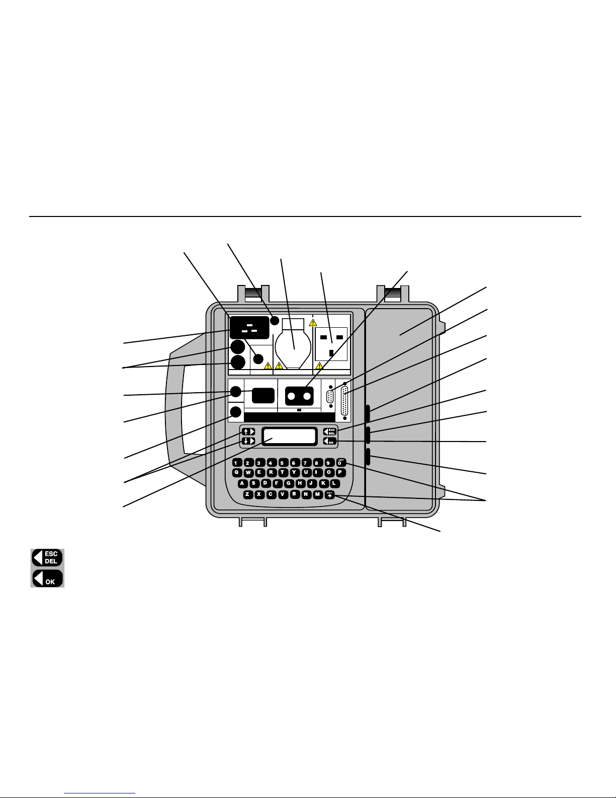
Features and Controls
TESTS
COMMS
CHECK-TEST
MENU
Auxiliary Earthing Point
(see Safety Warnings)
110V Appliance connection
230V Appliance connection
Fuse test points
LCD display
Multi-function
Soft keys
Earth
Continuity connection
(200mA)
Earth Bond Connection
Lead test Connection
13A protection fuses
Mains power Connection
230V or 110V
Flash test socket
(Class 2 equipment)
(PAT4 DVF only)
Lead/Accessory
Storage
Barcode scanner/ PC
connection
Parallel
PrinterConnection
FS2
ESC/DEL key and
Multi-function soft key
FS4
OK key and
Multi-Function Soft key
SPACE=SHIFT + 0
Flash Test
Operation
FS1
Multi Function keys.
ESCape back to previous screen or used to DELete typed text.
OK when there is no displayed function.
Page 7
7
Contrast Adjustment
PAT4 has been designed so that contrast adjustment will not normally be required unless working at extremes of temperature.
1 Press and hold the letter
‘C’ key during the full switch on sequence.
The Contrast screen is displayed.
2 Press the left hand keys repeatedly, to adjust the contrast as required
and press the
OK key.
Reset to default Settings
If desired, the PAT4 can be reset to the factory default settings, and re-instate the demonstration data.
Note:
All existing data and User configurations will be erased.
1 Press and hold the letter ‘R’ key during the full switch on sequence.
The adjacent screen is displayed:
2 Confirm the request using the
‘Y’ key. On completion, you will be returned
to the Login screen.
3 Use ‘AVO’ and ‘1 2 3 4’ as the User / Pin to re-start.
Shortcut to Comms Upload (from PC)
If there is no useful data stored in PAT4, and it is required to upload new data from a PC,
this short cut allows direct access to the “COMMS RECEIVE” mode.
1 Press and hold the letter
‘U’ keyboard key during the full switch on sequence
The ‘Erase Data’ screen is displayed.
2 Press
EXIT to cancel the erasure, or CONTINUE to proceed.
The ‘Are you sure ?’ screen is displayed.
3 Press the
YES key to confirm, or cancel by pressing the NO key.
Results print-out after test
PAT4 can be selected to print a short report of the test results immediately after each test. To toggle the status of this feature from off to on or vice
versa, press and hold the ‘P’ key during the full switch on sequence. Note: No screen is displayed to show that the change has occurred.
Setting Up
Contrast
Reset to defaults ?
Confirm (Y/N)
Erase all data
EXIT CONTINUE
Page 8
8
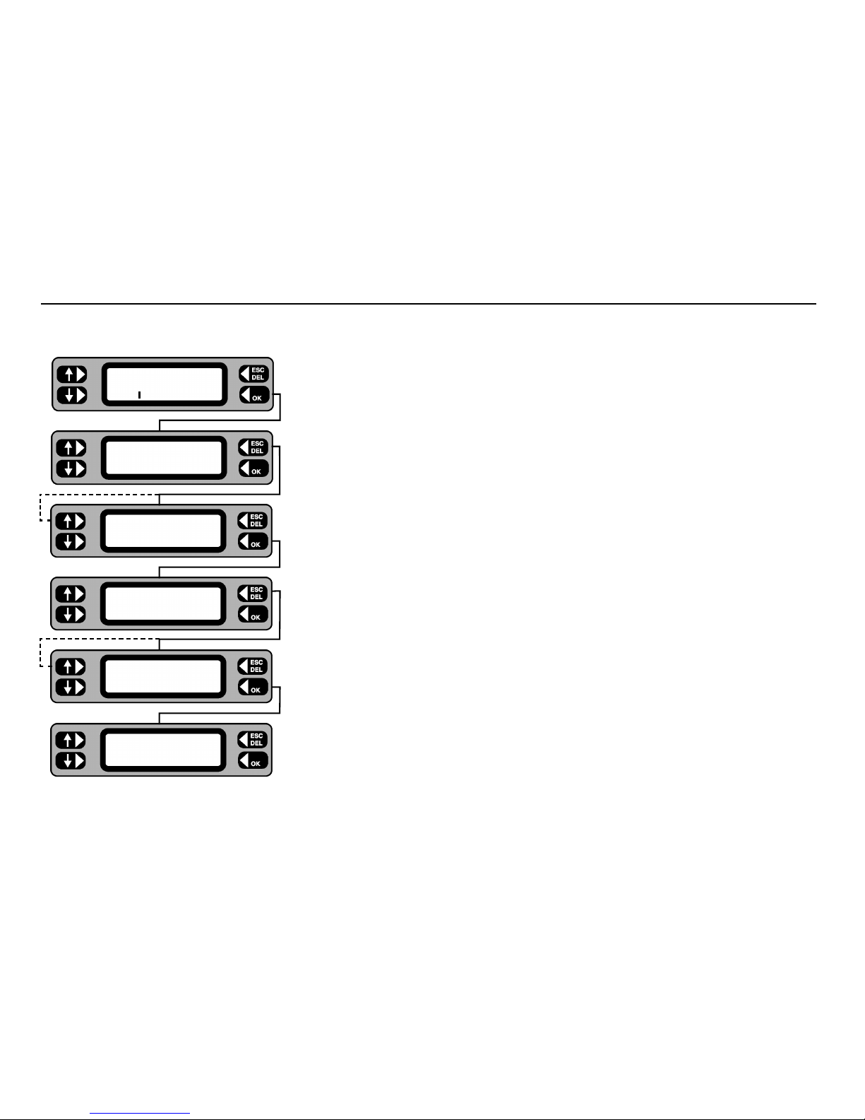
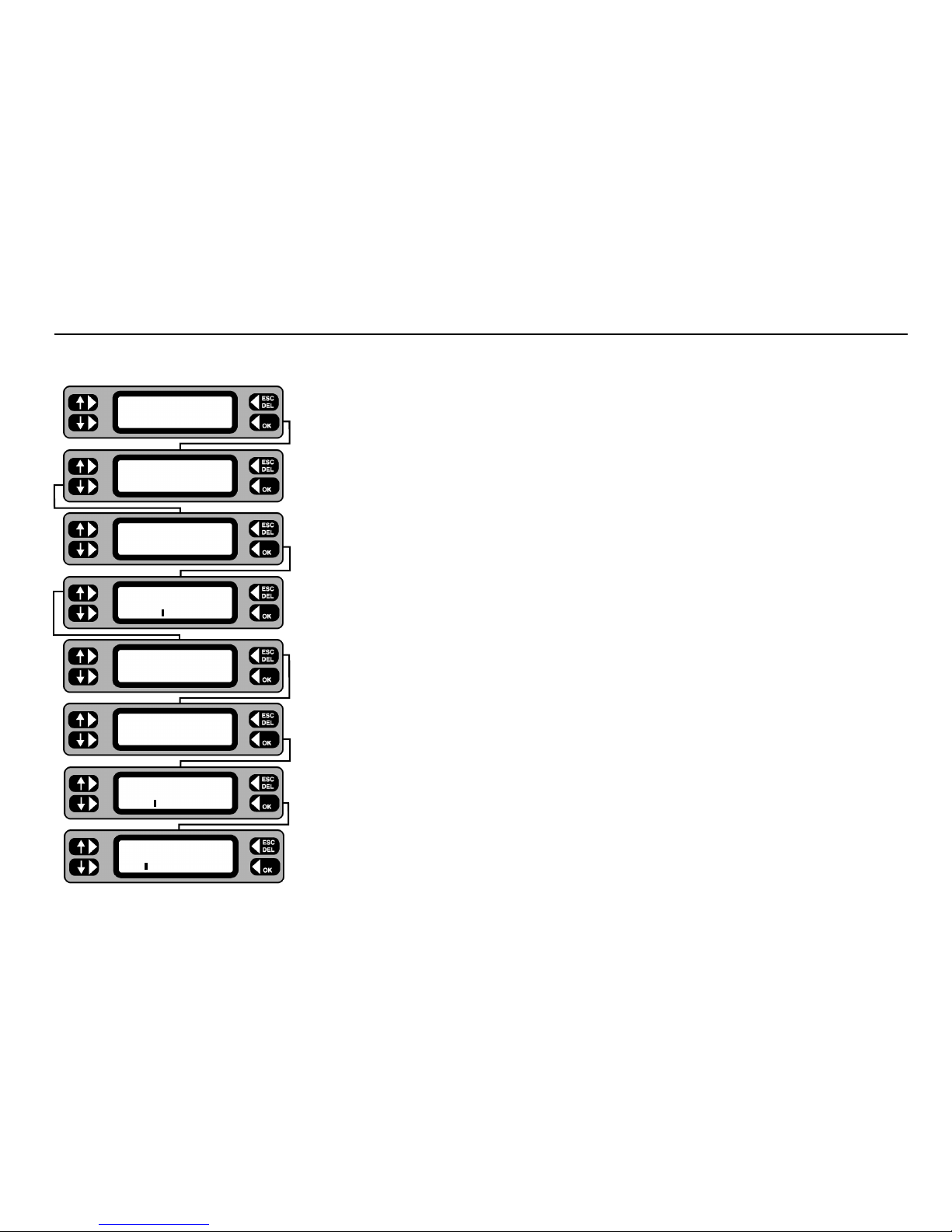
PAT4 accepts up to ten User names / PIN numbers at any one time, allowing only authorised persons to use the unit, if required. To input User names
and their respective pin numbers see ‘Settings’. Tests are attributed to the user that is currently logged in.
If you have not used the
PAT4 before:
1 Type in the name AVO. Typing errors can be deleted using the
ESC/DEL key. Press the OK key.
2 Type in the PIN number 1234 and press the
OK key. The current Client will be briefly displayeD
followed by the Client screen.
3 Press the
SELECT key. The Client Selection screen is displayed.
4 Press the NEXT key repeatedly. Each time the key is pressed, the next Client is displayed.
5 When the screen displays the desired client, press the
OK key. This selects the displayed client as
the current client. The ‘Location‘ screen is now displayed.
6 Press the
SELECT key in order to view and choose the site or building location.
7 Press the
NEXT key repeatedly. Each time the key is pressed the next location within
the selected client is displayed.
8 When the screen displays the desired location, press the
OK key.
This selects the displayed location as the site location you are currently using.
The Main screen is displayed.
Main Screen
The Client and Location need be selected only once for any particular site. PAT4 will assume the same settings until you deliberately logout from the Client. Even
if mains power is removed e.g. when moving around a site, if you have not logged out, the PAT4 will automatically return to the Main screen.
Logging in to the Unit
User:AVO
PIN: *
Client SELECT
LOGOUT ACCEPT
NEXT Client MORE
AVO INTERNATIONAL
Location SELECT
LOGOUT
NEXT Location MORE
ASHFORD SITE
TESTS QUICK-CHECK
COMMS MENU
Page 9
9
User names and Pin numbers
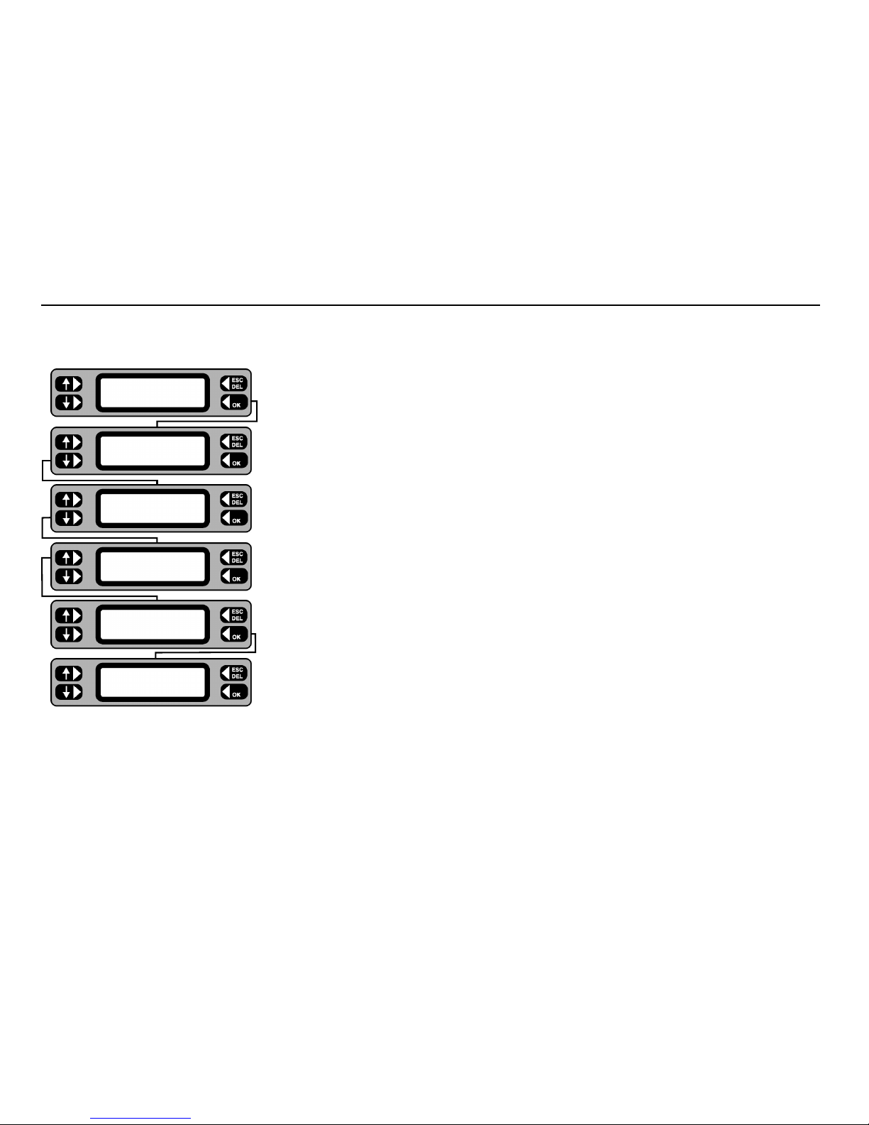
Names and Pin numbers for up to 10 authorised Users can be entered at any time. Test results are individually credited to the person logged in at the time of
testing and downloaded to Megger software if used.
1 From the Main screen, press the
MENU key.
2 From the Menu screen, press the SETTINGS key.
3 Press the
USERS key.
4 To check current Users, press the LIST key.
5 Use the left hand keys to scroll through the user list. The user who is currently logged in is displayed with an
asterisk * against the name. To edit or erase a user scroll until the required user is displayed.
6 Press the
MORE key. The softkey options are displayed. From this screen you can ADD a new user, EDIT or
ERASE the currently displayed user.
7 To add a new user, press the
ADD key.
8 Type in the new User name then press the
OK key.
9 Type in the desired PIN number (4 digits), press the OK key to save the user and PIN.
To login a different User, the current User must first be logged out - refer to the Client/Location Selection flow
chart - press the
LOGOUT key. The User/PIN screen is displayed.
TESTS QUICK-CHECK
COMMS MENU
ASSET
SETTINGS CLIENT
CLOCK
MISC USERS
LIST Users
LIST Users MORE
SMITH
ERASE Users
EDIT SMITH ADD
User
SMITH
PIN
5678
Page 10
10
Setup Manual / Autopass Testing / Fail buzzer
If ‘AUTOPASS’ is selected, testing will proceed automatically with PAT4 determining the pass/fail status according to the pre-selected Group limits. If
‘MANUAL’ is selected, PAT4 will pause after each test and display a “Pass” / “Fail” decision prompt. The buzzer can be set to sound when a test fails
in AUTOPASS mode. To mute the buzzer following a failure, press the OK key.
1 From the Main screen, press the
MENU key.
2 From the Menu screen, press the
SETTINGS key.
3 Press the
MISC key.
4 Press the
TEST SETUP key. The current Manual / Autopass setting is shown.
5 Using the lower left key, toggle the Manual / Autopass setting as required.
6 To set up the Fail buzzer, press the
BUZZER key. Using either the OFF or ON key,
switch the buzzer feature off or on as required.
7 On completion use
ESCape to back up to the Menu screen (and Main screen if required).
TESTS QUICK-CHECK
COMMS MENU
ASSET
SETTINGS CLIENT
CLOCK
MISC USERS
TEST SETUP
COMPANY MEMORY
TEST TIMES
AUTOPASS BUZZER
Fail buzzer OFF
ON
Page 11
11
Each test can be performed for a User definable time of between 5 and 60 seconds (5 and 20 seconds for Bond test). This enables
specific tests to be set to appropriate lengths of time, perhaps to satisfy a particular standard. Once set, a test time will automatically
be applied to all assets using such a test, regardless of the Group, Client or Location.
1 From the Main Screen, press the
MENU key.
2 Press the
SETTINGS key.
3 Press the
MISC key.
4 Press the
TEST SETUP key.
5 Press the
TEST TIMES key. The first test is displayed with its current time setting.
6 Operate the left hand keys to adjust the time for the selected test, then press the
OK key to
store the test time as displayed. The next test and it’s current duration is displayed.
Note: Press the
ESCape key at any time to exit test time setup.
7 When the final test time has been setup and
OK pressed, the display returns to the Test
Setup screen.
Setup Test Times
Flash test
5 s
Operation test
30 s
Insulation test
5 s
Continuity test
5 s
Bond test
5 s
TEST TIMES
AUTOPASS BUZZER
TEST SETUP
COMPANY MEMORY
CLOCK
MISC USERS
ASSET
SETTINGS CLIENT
Page 12
12
1 Press the MENU key.
2 Press the
SETTINGS key.
3 Press the
CLOCK key.
4 Press the
SET key. The Clock adjustment screen is displayed,
with the cursor flashing on a character.
5 Using the lower keys, move the cursor as appropriate and type in the required settings.
6 On completion of the setting, repeatedly press the
OK key to move the cursor to the extreme
right until it disappears.
7 Press the
OK key again to return to the Settings screen.
8 Use the
ESCape key to return back to the Menu screen.
Setting the Clock
TESTS QUICK-CHECK
COMMS MENU
ASSET
SETTINGS CLIENT
CLOCK
MISC USERS
Clock SET
4:03 17/09/00
Clock
4:03 17/09/00
Clock
4:03 17/09/00
Page 13
13
Setting up Test Company Title
PAT4 offers the ability to enter your Test Company title. This setup should not be confused with Clients and Locations. The Test
Company is the name of the organisation operating the PAT4. eg. ’XYZ Testing Ltd.’ Once entered, the company title will be printed
as the header on the reports available from PAT4.
1 Press the
MENU key.
2 Press the
SETTINGS key.
3 Press the
MISC key.
4 Press the
COMPANY key.
5 Type in the title of the testing company ( 20 characters).
Use the
DEL key to correct any typing errors.
6 On completion press the
OK key to return back to the Miscellaneous screen.
7 Press the
ESCape key to return back to the Menu screen.
TESTS QUICK-CHECK
COMMS MENU
ASSET
SETTINGS CLIENT
CLOCK
MISC USERS
TEST TIMES
COMPANY MEMORY
Company name
XYZ TESTING LTD
Page 14

14
Barcode Scanner
The optional PAT4 barcode scanner (6231-623) can be used to speed up the collection of asset data.
On subsequent visits it can also allow rapid retrieval of stored asset details when used in conjunction with barcoded asset labels.
PowerSuite
T
M
can be used to produce custom barcode labels, or alternatively pre-printed barcode asset labels are available from
Megger Limited (see Optional Accessories) and other sources.
The scanner is pre-programmed at the factory to interface with the
PAT4, and it will read the following bar code formats: Standard
Code 39, Code 128, Codabar, UPC-A/E, EAN-13, EAN-8.
The
PAT4 needs no setting up to use the barcode scanner, simply plug it into the 9-way D-type connector on the front panel of the
PAT4. The scanner will bleep a few times when it powers up.
The
PAT4 is set up to read barcodes when testing, editing or adding assets for the following fields:
Asset ID, Serial number, Asset Description and Group ID. When a barcode is scanned in these fields, the existing data is
overwritten by the data that has been scanned in, and the OK key is deemed to have been pressed.
To scan a bar code, hold the scanner so that the ‘mouth’ of the scanner is parallel with the barcode and close enough so that the light
from the scanner is illuminating the barcode. The scanner should read the barcode automatically (the trigger button on the scanner is
disabled). The scanner gives a short bleep when it reads a barcode.
If a barcode is scanned which is longer than the data field in the
PAT4, the data received will be truncated.
In order to be able to scan Asset Descriptions and Group ID’s, you will need to prepare a sheet containing the text barcodes you wish
to enter.
PowerSuiteTMcan print these barcodes.
Page 15

15
Clients and Locations
PAT4 maintains separate sets of assets (appliances) testing records by Client. Each Client may be allocated several Locations where
different sets of assets may be found. Up to 10 Clients and a total of 20 locations may be stored at any time.
CLIENT
LOCATION 1 LOCATION 2 LOCATION 3
LOCATION 1 LOCATION 2 LOCATION 3
Asset Records Asset Records Asset Records
This structure enables
PAT4 to separate the testing for each location, but maintains the overall traceability to the correct Client. It also
permits the same numbering sequences or asset IDs to be used for different Clients.
Where there is only one location, at least the Location name must be given; other address details can be omitted. Adding, editing or
deleting of Clients and Locations can be performed either directly after Login, or from the Main screen.
Page 16
16
1 From the Main screen, press the MENU key.
2 Press the
CLIENT key. The current client name is briefly displayed.
3 Press the
SELECT key. If the ACCEPT key is pressed, the current client is retained and
the display briefly shows the current location before moving onto step 6 below.
4 Press the
NEXT key to scroll through the name list until the required client’s
name is displayed.
5 Press the
OK key. The Location screen is displayed.
6 Press the
SELECT key. If the ACCEPT key is pressed, the current location is retained
and the display changes back to the Main screen.
7 Press the
NEXT key to scroll through the list and display the required location.
Note: - If no location exists for the selected client, the program will divert to the
Add location screen.
8 Press the
OK key. The Main screen is displayed.
Selecting an existing Client and Location
TESTS QUICK CHECK
COMMS MENU
ASSET
SETTINGS CLIENT
Client SELECT
LOGOUT ACCEPT
NEXT Client MORE
A.N.OTHER CLIENT
Location SELECT
LOGOUT ACCEPT
NEXT Location MORE
DOVER SITE
Page 17

17
1 From the Main screen, press the MENU key.
2 From the Menu screen, press the
CLIENT key.
The current client name is briefly displayed.
3 Press the
SELECT key.
4 If editing is required, display the required client by repeatedly pressing the
NEXT key,
then press the
MORE key. To add a client, just press the MORE key.
5 Press the
ADD or EDIT key as required.
6 Type in or edit the client name, press the
OK key when the Client name is complete.
7 Type in or edit the client address details, press the
OK key to step onto the next
address line.
8 When the final address line is complete, press the
OK key, the display will briefly
show the current client name.
9 Press
ACCEPT to go on to choose a location, SELECT to choose another
client or
LOGOUT to select another user.
Adding or editing a Client
Client SELECT
LOGOUT ACCEPT
Enter Address Line 3
Enter Address Line 2
Enter Address Line 1
Edit Client
A.N.OTHER CLIENT
ERASE Client E
EDIT
ADD
NEXT Client MORE
A.N.OTHER CLIENT
Client SELECT
LOGOUT ACCEPT
ASSET
SETTINGS CLIENT
TEST QUICK-CHECK
COMMS MENU
Add Client
Page 18

18
1 Select a client (see preceding instructions on how to do this) Press the SELECT key.
2 If editing is required, display the required location by repeatedly pressing the
NEXT key,
then press the
MORE key. To add a location, just press the MORE key.
3 Press the
ADD or EDIT key as required.
4 Type in or edit the location name, press the
OK key when the location name is complete.
5 Type in or edit the location address details, press the
OK key to step onto the next
address line.
6 When the final address line is complete, press the
OK key, the display will briefly show
the current location name.
7 Press
ACCEPT to return to the Main screen, SELECT to choose another location
or
LOGOUT to select another user.
Adding or editing a Location
Location SELECT
LOGOUT ACCEPT
NEXT Location MORE
DOVER SITE
ERASE Location
EDIT ADD
Edit Location
DOVER SITE
Enter Address Line 1
Enter Address Line 2
Enter Address Line 3
Location SELECT
LOGOUT ACCEPT
Add Location
Page 19

19
1 From the Main screen, press the MENU key.
2 From the Menu screen, press the CLIENT key. The current Client name is briefly displayed.
3 Press the SELECT key.
4 To erase a client, press the MORE key. To erase a location, press the OK key to choose
the location.
5 To erase a client, follow the right hand column. To erase a location,
follow the left hand column.
6 After erasing a client, a new current client must be selected.
After erasing a location, a new current location must be selected.
Erasing a Client or Location
NEXT Location MORE
FOLKESTONE SITE
Edit Location
DOVER SITE
ERASE Location
EDIT ADD
NEXT Location MORE
DOVER SITE
Location SELECT
LOGOUT ACCEPT
NEXT Client MORE
A.N.OTHER CLIENT
Client SELECT
LOGOUT ACCEPT
ASSET
SETTINGS CLIENT
TEST QUICK-CHECK
COMMS MENU
ERASE Client E
EDIT ADD
Erase Client
A.N.OTHER CLIENT
Client SELECT
LOGOUT
Page 20

20
Asset Test Groups
Appliances are referred to as “Assets”. For each asset a complete record is stored under the appropriate Client. Each asset record holds full details of
the equipment, i.e. ID; Description; Serial number; Fuse rating; Test Group, VA Rating, Test frequency, Room, and Test results.
ASSET ID
(Unique Reference)
ASSET RECORD
(e.g. Drill)
GROUP DETAILS ASSET DETAILS TEST RESULTS
(e.g. DRL2 (e.g. Description FOR ASSET
Drill Class 2 Fuse Rating
+ TEST SETUP VA Rating
+ TEST LIMITS Test Frequency
Serial number
Group Room
A Test Group is a set of pre-defined tests with associated pass / fail limits that are suitable for a specified type of asset (appliance). Up to 50 Test Groups
may be configured, each of which is identified by a User designated 3-character code. Every asset record contains a Group
PAT4 should use when
the appliance is tested.
Each Group contains the following information: Group Code: e.g. DRL
Group name: e.g. Drills
Voltage: 230V or 110V
Insulation Class: Class 1 = Earthed
Class 2 = Double insulated.
Tests to be applied: e.g. Bond test
Insulation test
Operation test etc.
When setting up a Group, any of the
PAT4 tests may be specified by placing a 3 next to the selected tests.
Note: The Earth leakage/touch current test is part of the Operation test – enable the Operation test to include an Earth leakage/touch current test.
Page 21

21
Asset Test Groups
For each selected test, PAT4 allows one of twelve pass band options to be selected.
Earth Bond: Pass < 50Ω, 100Ω, 200Ω, 300Ω, 400Ω, 500Ω, 600Ω, 750Ω, 800Ω, 1.0Ω, 1.5Ω, 2.0Ω
Continuity: Pass < 50Ω, 100Ω, 200Ω, 500Ω, 750Ω, 1.0Ω, 1.5Ω, 2.0Ω, 2.5Ω, 5.0Ω, 7.5Ω, 10Ω
Insulation: Pass > 0.25Ω, 0.3Ω, 0.5Ω,1Ω, 2Ω, 4ΩM, 5Ω, 7Ω, 8Ω, 10Ω, 20Ω, 50Ω
Operation: Pass < 50VA, 100VA, 200VA, 350VA, 500VA, 700VA, 1000VA, 1200VA, 1500VA, 2000VA, 2500VA, 3000VA
Earth Leakage: Pass < 0.25mA, 0.5mA, 0.75mA, 1mA, 1.5mA, 2mA, 3.5mA, 5mA, 7mA, 7.5mA, 10mA, 15mA.
Extension lead:
Checks for correct polarity, open circuit and short circuit faults. Earth Bond Test. Insulation test.
(PAT4DVF)
Flash: Pass 0.2mA, 0.3mA, 0.4mA, 0.5mA, 0.6mA, 0.75mA, 1mA, 1.2mA, 1.5mA, 2mA, 2.5mA, 3mA
Note 1: Once a Group is defined, every appliance
using that group will have the same tests and limits applied
Note 2: For convenience, all Groups test for 110V assets which do not
include an Operation test can be carried out using a 230V mains connection,
and all Group tests for 230V assets which do not include an Operation test may be carried out using a 110V mains connection. An attempt to test an
asset with an alternative voltage, when the test Group includes an Operation test, will be inhibited, and the message “Test needs xxxV please change
supply” will be displayed.
Example:- Test Group for kettles as follows:
Group Code: KET
Group Description: Kettles
Voltage: 230V
Insulation Class: Class 1
Earth Bond Test Pass < 100Ω
,
Insulation: Pass > 2Ω
Operation: Pass < 2500 VA
Earth Leakage/Touch current: Pass < 2 mA
Flash (not applicable)
Page 22

22
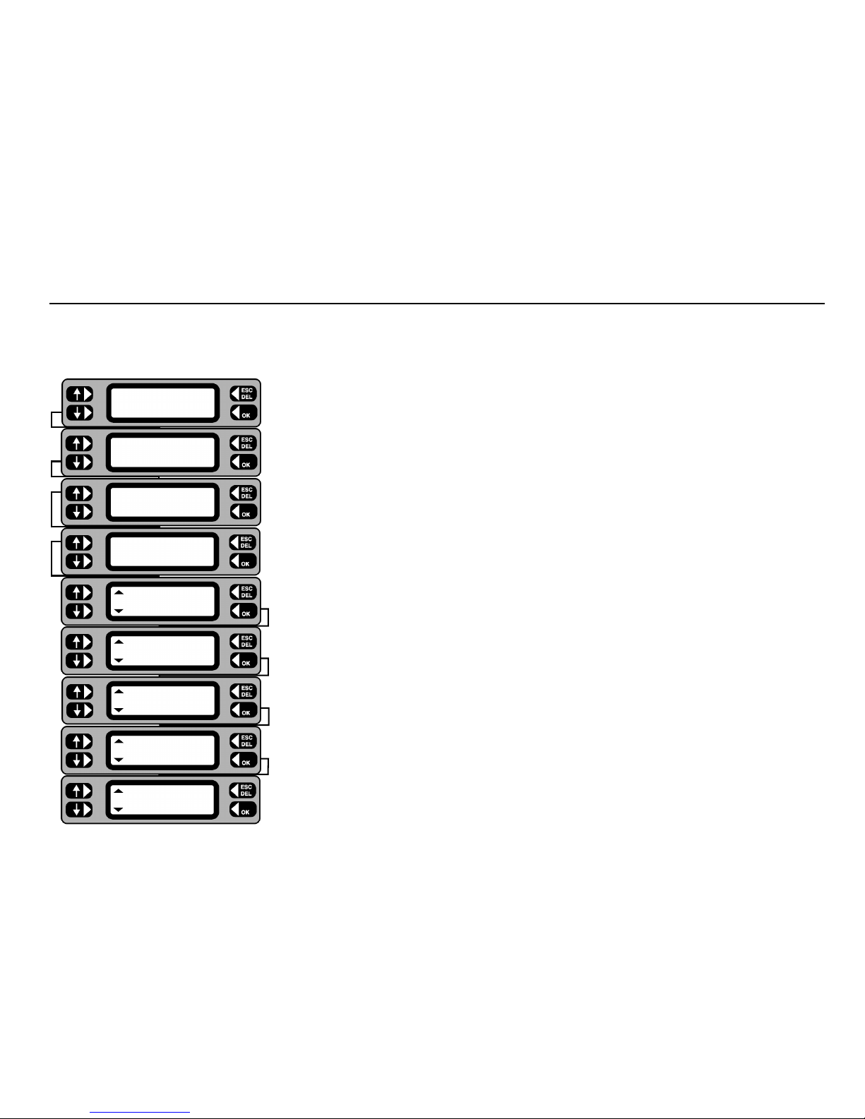
1 From the Main screen, press MENU.
2 From the Menu screen, press
ASSET.
3 From the Assets menu, press
GROUPS.
4 To add, enter the new group code and press
OK.
To edit or erase, either enter the group code and press
OK, or press LIST and scroll through the
groups. When the required group is displayed, press the
MORE key, followed by EDIT or ERASE as required.
If erasing, press
OK on the confirmation screen to proceed with the erase.
5 Type in/edit the description of the group (10 characters max.) and press the OK key.
6 Select 230 Volt or 110 Volt assets by using the up/down Keys. Complete the selection using the
OK key.
7 Press the up/down keys to change to the required Insulation Class. Continue by pressing the
OK key.
8 Operate the up/down keys to scroll through the available tests for the group. The
OK key toggles the test on and
off, a 3 indicating that the test is enabled. Note:- Earth Bond/Continuity tests are available for Class 1 items only.
When all required tests have been included, press the EXIT key.
If a Bond test has been selected an additional screen allows selection of the test current.
9 For each test limit, toggle the up/down keys until the required setting is displayed, then press the OK key to save
the setting.
10 To save the new group to the memory, press the YES key. To cancel press the NO key.
Adding, editing or erasing a Group
TESTS QUICK-CHECK
COMMS MENU
TESTS QUICK-CHECK
COMMS
MENU
TESTS QUICK-CHECK
COMMS
MENU
TESTS QUICK-CHECK
COMMS
MENU
TESTS QUICK-CHECK
COMMS
MENU
Voltage
230V
Group name
DRILLS
Group code
DRL
ERASE Group
EDIT DRL ADD
Group MORE
DRL
LIST Group
ASSETS
GROUPS REPORTS
ASSET
SETTINGS CLIENT
Tests EXIT
Insulation
Insulation Class
Class 2
Insulation limits
>0.5MΩ
Save group to memory
NO
YES
Add as a new group?
NO YES
3
Page 23

23
Assets
Up to 1000 assets may be stored at any one time in the PAT4, each with their current and previous (Historic) test results. Appropriate
asset details may be entered before or during testing. Once the asset record has been set and stored, it never needs to be re-entered.
The next time the asset is tested, only the asset ID number needs be entered or scanned, and the PAT4 will recall the complete record
with the correct Group code and all the asset details. Testing follows automatically. This approach ensures that once set up, there is
no chance of the wrong tests being applied to the asset, as is possible with instruments that require a test code to be specified each
time that an asset is tested.
The Asset database contains the following details for each asset:
Asset ID – a unique code number (within a particular client), upto 10 characters long. For speed this may be scanned in rather than
typed.
Group ID – a code (upto three characters) which identifies which test group should be used when testing the asset. Once again this
code may be scanned in, if the tester has a prepared sheet with all the Group ID printed as barcodes.
Serial number – to identify the asset precisely the serial number should be recorded – this may be scanned in too (since many assets
now have barcoded serial numbers on them). A maximum length of 15 characters is permitted.
Asset description – a description of the asset, e.g. Manufacturer & Model. This may be scanned too – a prepared sheet with asset
descriptions in barcode form must be available. The Asset description may be 20 characters long.
Room ID – in larger organisations, it may be useful to describe the location of an asset more precisely by specifying a Room ID. The
PAT4 remembers the last Room ID specified to save typing it in repeatedly. The Room ID may be upto 10 characters long.
Retest frequency – the retest frequency is set to 12 months by default, but the user may override this to set a different frequency
between 1 and 255 months.
VA Rating – the user may optionally specify the Asset’s VA rating – often expressed in Watts. It is not permitted to enter anything
above 3000.
Fuse rating – the fuse rating may be selected from a scrolling down list – the options are: None, 1A, 2A, 3A, 5A, 10A, 13A.
Page 24

24
Adding an Asset
TESTS QUICK-CHECK
COMMS MENU
TESTS QUICK-CHECK
COMMS MENU
TESTS QUICK-CHECK
COMMS MENU
TESTS QUICK-CHECK
COMMS MENU
TESTS QUICK-CHECK
COMMS MENU
Retest Frequency
6 months (<225)
Room ID
Workshop
Asset description
Table fan - 9 inch
Serial number
435576
Short cut to tests
TEST CONTINUE
LIST Group
ASSET ID
1068
ADD Test
SEARCH SELECT
Fuse rating
5A
Asset VA rating
30
Save asset to memory
NO YES
Asset 1068 saved
1 From the Main screen, press the TESTS key.
2 Press the
ADD key.
3 Scan in, or type in the asset ID (≤10 characters) for the new asset and press the
OK key.
4 Scan in, or type the Group ID (≤ 3 characters) and press the
OK key.
5 Press the
CONTINUE key.
6 Scan in, or type the asset serial number and press the
OK key.
7 Scan in, or type in the asset make/model description and press the
OK key.
8 Accept the displayed room ID, or type in a new room ID name and / or number and press the
OK key.
9 Accept the default re-test frequency of 12 months, or type in the specified number of months between tests and
press the
OK key.
10 Type in the VA rating for the asset (often indicated as Watts) and press the
OK key.
11Toggle the left-hand keys to display the fuse rating for the asset and press the
OK key (for assets without fuses,
NONE may be selected).
12 To save the new asset to the memory, press the
YES key. The option to Test asset now is given. Press the YES
key to enter directly into the sequence for the selected Group.
13 To abort the new asset, press the
NO key. The details are not saved and the screen returns to the Test screen.
14 Press the
ESCape key to return to the Main screen.
Note:-Instead of pressing the CONTINUE key (at step 5) you may prefer to press the TEST key. This will by-pass the addition of all the remaining asset details
and allows you to perform the test straight away. It is recommended that full details are entered, since these enable other features to operate such as the facility
to locate an asset by Room ID.
Page 25

25
TESTS QUICK-CHECK
C
OMMS MENU
TESTS QUICK-CHECK
COMMS
MENU
TESTS QUICK-CHECK
COMMS
MENU
TESTS QUICK-CHECK
COMMS
MENU
TESTS QUICK-CHECK
COMMS
MENU
LIST Group
NEXT Location
Anytown
Asset ID
1068
ERASE Asset
EDIT 1068 ADD
NEXT Asset MORE
1068
LIST Asset
1068
ASSETS
GROUPS REPORTS
ASSET
SETTINGS CLIENT
Asset description
Table fan - 9 inch
Serial number
435576
Save asset to memory
NO YES
Asset 1068 saved
Editing or erasing an Asset
1 From the Main screen, press the MENU key.
2 Press the
ASSET key.
3 Press the
ASSETS key.
4 Scan in, or type in the ID for the required asset and press the
OK key. Alternatively, press the LIST
key, then step through the assets using the NEXT key.
5 If the asset ID is recognised, the Asset screen with options to
ERASE, EDIT or ADD is displayed.
6 To edit, press the
EDIT key. Each subsequent screen allows amendments to be made for the selected
asset. Press the
OK key to sequentially step through the details.
To erase, press the
ERASE key. At the confirmation screen, press the OK key to erase the asset, or
ESCape to abort the erase.
7 To save the amended asset details to the memory, press the
YES key. The screen returns to the Asset
list screen. Press the ESCape key to return back to the Menu screen.
8 To abort the operation, press the
NO key. The Asset screen is displayed.
Page 26

26
It may be necessary to locate and test an asset (for the current Client) for which only the Location, Test Group, or an approximate retest date is known.
Search by location (Location or Room)
1 From the Main screen, press the TESTS key.
2 From the Test screen, press the
SEARCH key.
3 Press the
LOCATION key.
4 Continue the search by selecting
ROOM or LOCATION. The screen changes.
Note: - In order to search by ‘Room’, the room ID must be specified in the asset details.
5 If
ROOM is selected, toggle the NEXT key to step through the list of rooms and display the required
room. Press the
OK key.
6 If
LOCATION is selected, toggle the NEXT key to step through the list of locations and display the
required location. Press the OK key.
7 Toggle the NEXT key to step through the list of assets and display the required asset ID. Press the
TEST key. The Test screen is displayed.
8. Follow the Test Asset routine.
This facility is very useful if you have to test assets in a large organisation, with many different rooms. You may start in any room or location, and call
up all the assets for testing before moving on to the next room or location
Locate an Asset
TESTS QUICK CHECK
COMMS MENU
ADD Test
SEARCH SELECT
DATE Search
LOCATION GROUP
Search
ROOM LOCATION
NEXT Room ID
Workshop
NEXT Search
ID: PT736 TEST
NEXT Location
Anytown
Page 27

27
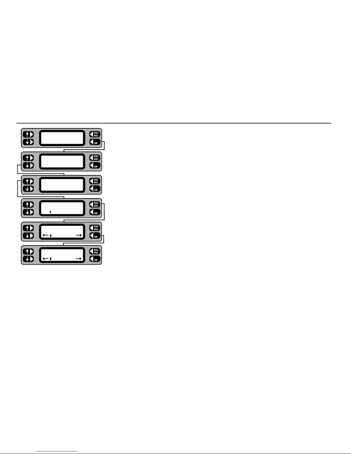
1 From the Main screen, press the TESTS key.
2 Press the
SEARCH key.
3 Continue the search by selecting either GROUP or DATE.
4 For Group search, type in the 3-character code for the Group and press the
OK key.
Note:-If unsure of the Group code, press the
LIST key to step through the list of Group
codes. Then press the OK key.
For search by test due date, type in the date after which the test becomes due and press
the
OK key, then type in the date before which the test is due and press the OK key.
5 Toggle the
NEXT key to step through the list of assets and display the required asset
ID.
6 Press the
TEST key. The Test screen is displayed.
7 Follow the Test Asset routine.
Search by Test Group or Test due date
TESTS QUICK CHECK
COMMS MENU
ADD Test
SEARCH SELECT
DATE Search
LOCATION GROUP
Test due after
/ /
Test due before
/ /
NEXT Search
ID: PT736 TEST
Group
DRL
LIST Group
Page 28

28
PAT4 will apply each of the allocated tests for the appropriate Group, in the correct sequence. If AUTOPASS has been selected under the SETTINGS
option, testing will proceed automatically with PAT4 determining the pass/fail status according to the pre selected Group limits. If MANUAL has been
selected, PAT4 will pause after each test and display a Pass / Fail decision prompt. An asterisk is placed against either the PASS or FAIL button depending
on the whether the value falls within the Test Group’s passband.
PAT4 will conduct a pre-test to confirm that electrical continuity exists within the appliance i.e. that it has been switched On, and that any fuses present are
not ruptured. If the asset is very high or very low resistance,
PAT4 will warn that the asset may accordingly be Open or Short Circuit. You have the option
of RETRY (asset turned On?) FAIL, or IGNORE the warning. Some assets containing heating elements, filament lamps or large motors may offer very low
resistance in their de-energised state, causing PAT4 to warn of a possible short circuit. In such cases, the warning can be ignored. When all required tests
have been completed the results may be stored in PAT4 memory.If a printer is attached to PAT 4 ’s parallel output, a simple listing of test results can be
printed. If a printer is not attached or this feature has been disabled (See Settings section),
PAT4 will automatically skip the printing process.
1 From the Main screen, press the
TESTS key.
2 Press the
SELECT key.
3 Scan in, or type in the code for the required asset and press the
OK key.
4 If the asset is recognised, the option to update the asset data is offered. Press the
YES key to enter
the ‘Edit Asset’ routine or the NO key to test the asset now.
5 If previous test results are stored, the date last tested is displayed. Press the
OK key.
The tests selected in the asset’s test group follow on from this point. Refer to the Description of Tests
for detailed information on each test.
6 Enter a repair code – if required.
XPress softwareTMfor Windows has 99 built in codes which
you can use when appliance testing to record repair details against tests.
Testing an Asset
TESTS QUICK-CHECK
COMMS MENU
ADD Test
SEARCH SELECT
Asset ID
1068
Update asset data
NO YES
Last tested
17/02/98
Repair Code
Page 29

29
Auto Restart to Main Screen
The Client and Location need be selected only once for any particular site. PAT4 will assume the same settings until you deliberately logout from the
Client. Even if mains power is removed e.g. when moving around a site, if you have not logged out, the
PAT4 will automatically return to the Main
screen. You are now ready to test appliances.
Repair Codes
XPress software
TM
for Windows has 99 built in codes, which you can use when appliance testing to record repair details against tests. With your PAT4
at the end of the test, you can enter one of these codes and Xpress software will automatically update the repair information in the unassigned or
assigned data maintenance programs.
Within
XPress softwareTMyou can modify the descriptions and add any charge for the repair. The charges will automatically be used on job costing and
invoicing. A full list of repair codes currently included is shown opposite. This list may be copied and fixed inside the lid of the test instrument for easy
reference if this feature is to be used. If a repair codes are not required simply press the
ESCape key when the code is requested at the end of the
test.
Code
Description Code Description
1. Replace internal fuse. 18. Renew 3core 0.75mm2flex
2. Refit plug. 19. Renew 3core 1.00mm
2
flex
3. Refit socket. 20. Renew 3core 1.50mm
2
flex
4. Replace cable 21. Renew 3core 2.50mm
2
flex
5. Renew 415V 5 pin 16A 22. Tighten Cord Restraints
6. Renew 415V 4 pin 32A 23. Replace Control Knobs.
7. Renew 415V 5 pin 32A 24. Tighten Case fixings.
8. Renew IEC connector 6A 25. Replace Indicator Lamps.
9. Renew IEC connector 10A 26. Replace case parts
10. Renew IEC connector 16A
11. Replace Main Switch.
12. Replace Fuse Holder.
13. Replace Missing Screws
14. Replace Warning Labels
15. Renew 2core 1.00mm
2
flex
16. Renew 2core 1.50mm
2
flex
17. Renew 2core 2.50mm
2
flex
Page 30

30
PAT4 incorporates a historic data facility that enables previous test results to be viewed at the time of testing. This powerful feature enables you to spot
any dangerous degradation of the appliance since its last test. Whilst previous and current test results may each be considered acceptable in their own
right against the pre-defined limits, there are instances where two very different readings will indicate significant degradation of appliance safety. e.g.
Insulation test March 1998 = 50 MΩ Pass limit = 7 MΩ
Insulation test March 1999 = 10 MΩ Pass limit = 7 MΩ
Both readings are clearly a pass, but if the degradation continued it would not be long before the asset insulation fell below the limit of 7 MΩ causing
the appliance to fail the pre-set limits.
Historic test data can only be viewed in Manual test mode (see Setup Autopass/Manual testing). When historic test data is available the test result
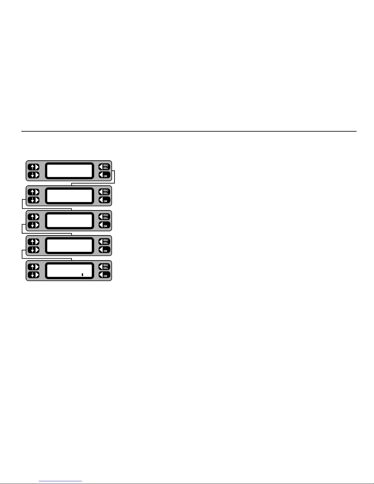
screen changes slightly. See the insulation test example below.
From previous test
1 The Insulation resistance is displayed. The asterisk symbol (*) in the top left corner indicates that historic
data is present. To view the historic data, press the asterisk key.
2 This example shows that the last insulation test result stored in memory is > 50MΩ and the
3 indicates
that this was a pass at the last test. If the asset had failed the test an 8 would be displayed.
3 To revert to the current test result simply press the asterisk * key again and
PASS or FAIL the test. The
test sequence for the appliance continues.
To next test
PAT4 stores both the current and the previous test results for each asset.
When data is uploaded to
PAT4 from XPress softwareTM, the historic data will also be transferred. However, data will not be transferred if the previous
test was not performed using a PAT4.
Historical Data
* Insulation Res.
FAIL >50MΩ *PASS
* Insulation Res.
Mem >50MΩ
3
* Insulation Res.
FAIL >50MΩ
*PASS
Page 31

31
It is often useful to perform a particular test on an asset in isolation. If for instance an asset had previously failed a particular test and had subsequently
been repaired it may be useful to verify the repair before commencing with a full test sequence. Alternatively the test could be used during repair in
order to highlight the area at fault. Quick-check enables the selective application of any of the tests that would normally be applied to the asset. The
asset ID is entered in the normal way, recalling the asset record. The individual tests specified for the asset group will then be displayed, allowing any
one to be run independently. In Quick-check mode no results are stored and the asset history is not changed.
1 From the main screen, press the QUICK-CHECK key.
2 Scan or Type in the Asset ID and press the
OK key.
3 Toggle the left-hand keys to display the required test from the list pre-set for the group.
Operation and earth leakage tests will not be available unless the asset supply voltage agrees with the
actual
PAT4 supply voltage.
Ensure that the correct leads and configurations are used for each test. Refer to the diagrams located
inside the lid of the PAT4.
For an Operation test, ensure that the asset is in a safe condition to run and
that no hazards are present.
4 Appropriate on-screen warnings are displayed for the selected test. Comply with all instructions and
press the OK key to continue.
5 Quick-Check results are displayed. Press the
OK key.
6 Press the
YES key to repeat the same test or press the NO key to return back to the
Quick-Check selection screen.
7 Use the ESCape key to return to the Main screen.
Quick-Check
TESTS QUICK-CHECK
COMMS MENU
Asset ID
PT762
Quick checks
Insulation test
Pre-testing asset
. . . .
Insulation test
Last connected
? Yes
Insulation test 3
> 50 M Ω
Insulation Res.
> 50 M Ω
Retest asset
NO YES
Page 32

32
From time to time you may wish to permanently erase all or part of the memory on your PAT4 . Options are as follows-:
• Erase Groups • Erase Clients
• Erase Locations • Erase Assets
• Erase Results • Erase Setup
• Erase ALL
1 From the Main screen, press the
MENU key.
2 From the Menu screen, press the SETTINGS key.
3 Press the MISC key.
4 Press the MEMORY key.
5 Toggle the left-hand keys to display the item to be erased.
6 Press the OK key. The selected items are erased.
Note 1: - Once erased, the data cannot be un-erased.
7 On completion press the ESCape key to return back to the Menu screen.
Note 2: - Erasure of Clients or Locations will include all related assets, and is pre-empted by a check. Confirm (OK key) or cancel (ESC key) to continue.
Note 3: - On completion of the erasure routine, PAT4 returns to the Login screen for ‘Erase All’ and to the Client screen for ‘Erase Locations’ and ‘Erase
Client’.
Note 4: - Prior to erasing assets or results,
PAT4 performs a check on the number of assets or results to be erased. Confirm OK or cancel (ESCape key).
Erase Memory
TESTS QUICK-CHECK
COMMS MENU
ASSET
SETTINGS CLIENT
CLOCK
MISC USERS
TEST TIMES
COMPANY MEMORY
ERASE
All
Now erasing
Page 33

33
A variety of reports are available for printing directly from the PAT4, providing the advantages of hard copy output on site. PAT4 permits the printing of
the following range of reports:
• Client List • Location List
• Plain Asset List † • Assets with Current Results (Certificate of Test) †
• Retro report • Groups
• Assets with Due dates for testing †
All reports are printed directly from the
PAT4 using the parallel printer connector on the front panel.
† The asset and results reports indicated list the assets and results that relate to the current Client and Location.
The ‘Retro’ report produces a report which is compatible with the data which may be downloaded into “Shire’s” ‘Safety First’, ‘Safety First+’ packages.
However it must be remembered that the output for this report selection will appear on the parallel output of the PAT4. The above software packages
can only receive data via a PC serial port. It will therefore be necessary to pass the data through a parallel to serial converter, if you wish to download
from the
PAT4 to any of these packages. These are readily available at low cost from many sources.
1 From the Main screen press the MENU key.
2 Press the ASSET key.
3 Press the REPORTS key.
4 Toggle the left-hand keys to display the report to be printed.
5 Press the
OK key. The selected report is printed.
6 On completion
ESCape back to the Menu screen.
If a printer is attached to
PAT4’s parallel output during the testing of assets, a simple listing of test results can be printed at the end of each test. (This
feature must be enabled first - see Settings section).
Printing Reports and Results
TESTS QUICK-CHECK
COMMS MENU
ASSET
SETTINGS CLIENT
ASSETS
GROUPS REPORTS
Reports
Clients
Printing Report
Page 34

34
Download/Upload Data
PAT4 is designed to be used in conjunction with Download ManagerTMor XPressTMsoftware for WindowsTMwhich can send and receive fields within
its database to form a highly integrated portable appliance testing system. PAT4 may be controlled from Download ManagerTMor XPressTMsoftware,
providing a centrally administered testing regime. In this way the manipulation of large quantities of data is handled on a PC, each
PAT4 acting as a
slave to receive information on Clients, Locations and assets to be tested. The data and test results can then be downloaded to the PC as convenient.
To download or upload data, the PAT4 needs to be connected to a PC running suitable download software i.e. Download ManagerTMor XPress
TM
software for WindowsTM.
XPressTMsoftware for Windows
TM
This Windows package produces certificates for Portable Appliance Testing. The database stores a wide variety of appliance and customer information,
together with a full test history. Test data may be edited, repairs added and power searches and sorts performed.
Serial Lead Connections
A 9 way lead is supplied with the PAT4. The following table indicates the lead format required. Some PCs require a 25 way connector.
Signal
DCD
RXD
TXD
DTR
GND
DSR
RTS
CTS
+5V
PAT4
1
2
3
4
5
6
7
8
9
PC
9 way ‘D’
7
3
2
6/8
5
4
1
4
9
PC
25 way ‘D’
4
2
3
5/6
7
20
8
20
22
Page 35

35
1 Connect the PAT4 to the PC, and prepare the PC software to receive the data.
2 From the Main screen, press the COMMS key.
3 Press the
SEND key.
The display may briefly display ‘Connecting’ as it establishes a connection with the PC.
4 If the PAT4 detects that the PC software is not set up to work with the latest IEE Code of
Practice pass limits, PAT4 will prompt whether you want to convert the downloaded group
data to use the nearest pass limit available.
5 The display shows that the data is downloading.
Download to a computer
TESTS QUICK-CHECK
COMMS MENU
ASSET
SETTINGS CLIENT
Convert test limits
NO YES
Sending...
Page 36

36
1 Connect the PAT4 to the PC, and prepare the PC software to send the data.
2 From the Main screen, press the
COMMS key.
3 Press the
RECEIVE key.
4 Press the
CONTINUE key.
Note:- This will erase all current data. Only proceed if this data has been downloaded first,
or is of no further use.
5 Press the
YES key – all the data in the PAT 4 will be erased, then it will start receiving data
from the PC.
6 The database is cleared prior to receiving the data from the PC.
The display should briefly display ‘Connecting’ as it establishes a connection with the PC.
7 The display shows that the data is being received.
Upload from a computer
TESTS QUICK-CHECK
COMMS MENU
SEND Comms
RECEIVE
Erase all data
EXIT CONTINUE
Are you sure
NO YES
Clearing database
Receiving...
Page 37

37
Visual Inspection List.
The Visual Inspection is to check the condition of:
• Case for damage; tears; cracks. • Supply socket.
• Mains Plug. • Environment e.g. operational hazards nearby.
• Mains Lead. • Suitability i.e. used for correct purpose.
• On/Off Switch. • Everything Else.
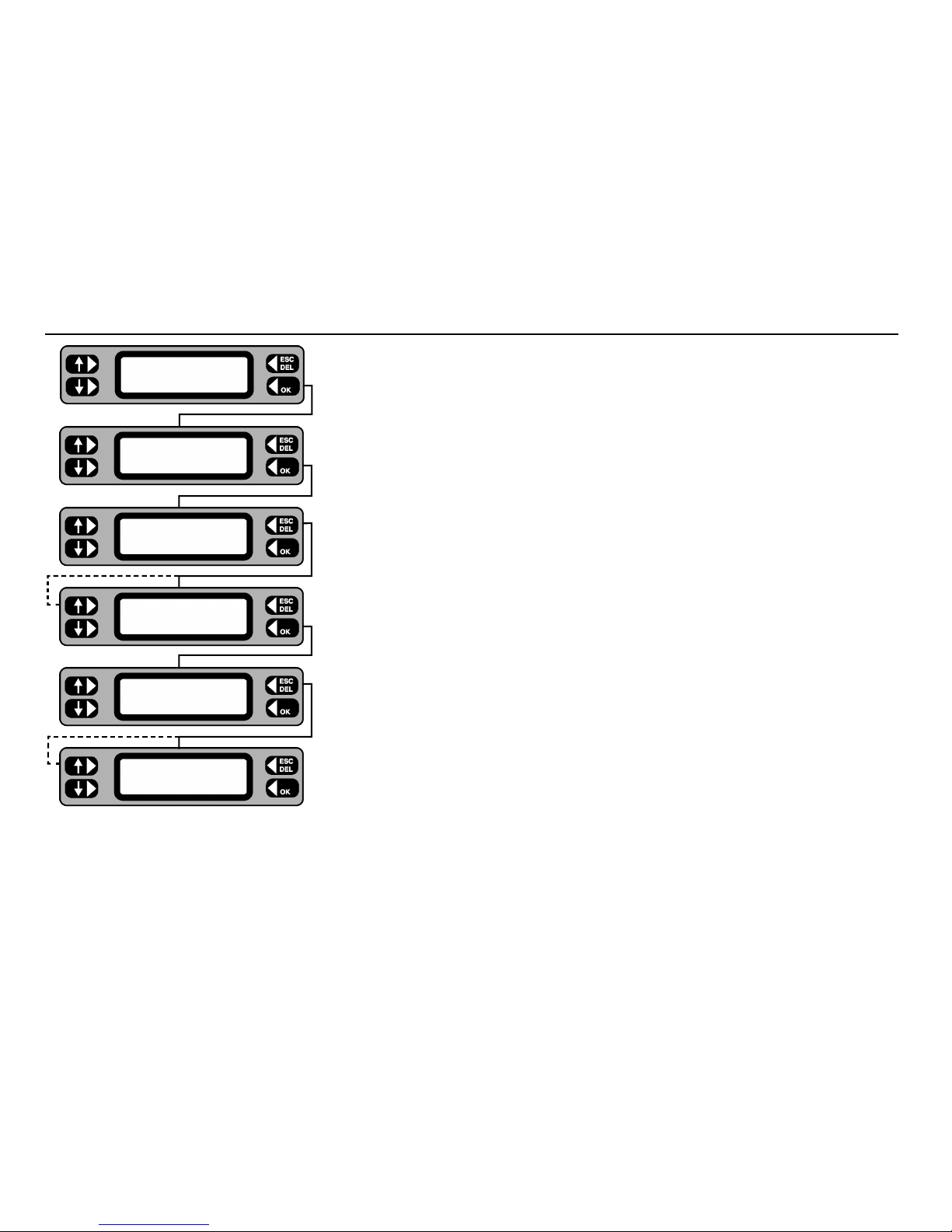
1 The test screen prompts the user to select either
PASS or FAIL, if PASS is selected the test will progress
onto the next selected test in the group.
2 If FAIL is selected, then the screens will prompt to specify the nature of all the faults noted.
3 Press YES or NO to specify the Visual inspection failures.
4 Check for any hazards in the vicinity, e.g. asset is exposed to water.
5 Check asset is suitable for the task it is being used for.
6. Any other hazards present.
Note: - If an asset fails the visual inspection, no further tests will be performed and a repair code may be entered (see ‘Repair Codes‘)
.
Description of Tests
Visual Inspection
FAIL PASS
TESTS QUICK-CHECK
COMMS
MENU
TESTS QUICK-CHECK
COMMS
MENU
TESTS QUICK-CHECK
COMMS
MENU
TESTS QUICK-CHECK
COMMS
MENU
Everything else OK?
NO
YES
Suitability OK?
NO
YES
Environment OK?
NO YES
Supply socket OK?
NO
YES
On/Off switch OK?
NO YES
Mains lead OK?
NO YES
Mains plug OK?
NO YES
Case OK?
NO YES
Page 38

38
Description of Tests
Earth Bond Test
In order to adequately test the integrity of the appliance earth conductor, high current (10A or 25A a.c.) is passed between the Earth Bond terminal and
the appliance test socket earth pin. The current may be set to 10A or 25A (calibrated at 0.1). The PAT4 can store upto three separate earth bond test
results for each asset test.
The
PAT4 contains thermal overload protection, which may operate in extreme cases of repeated earth bond testing. The message “Bond test is too
hot” will be displayed and the test will be aborted. Testing may recommence after a 10 minute cooling period. If this occurs frequently, refer to Settings
and reduce the Earth Bond test time. We recommend a duration of 5 seconds for this test.
1 Connect the bond lead to a suitable point on the asset under test. Press the
OK key.
2 When the test finishes the final result is shown. If the result is OK, press PASS,
then to store the result press LOG.
If subsequent Bond tests are not required press the
SKIP key when prompted to connect
the Bond lead again.
3 If the Bond resistance is too high, press the
FAIL key. If the asset has a long supply lead you can
compensate the Bond reading to allow for this by pressing the COMP key. To fail the asset immediately,
press the
LOG key.
4 Enter the lead length in metres.
5 Use the Up/Down keys to select the cross sectional area of the earth conductor.
6 The Bond Resistance is re-displayed taking into account the supply lead resistance.
Press
PASS or FAIL as appropriate.
Earth Continuity Test
This test provides a measurement of protective conductor resistance and is therefore applicable to Class 1 assets only. This test is usually applied to
equipment which may be damaged by the high current Bond test (e.g. I.T. equipment).
A low current (D.C.) is passed between the Continuity terminal and the appliance test socket Earth pin. The test current is limited to 200 mA with a
maximum open circuit voltage of 4 V. To use this test the Continuity terminal and the black lead should be connected to the appliance’s exposed
metalwork. On completion of the Continuity test, ensure that the black earth lead is disconnected from the appliance under test.
The procedure for this test is very similar to the Bond test (some screen titles are changed).
10A Bond Lead
Connected? YES
Bond Resistance
FAIL* 0.069
Ω
PASS
Wire mm
2
1.0 (10A)
Lead length (m)
10
Fail or retest COMP
RETEST LOG
Bond Resistance
FAIL* 0.284 Ω PASS
Pass or retest
RETEST LOG
10A Bond Lead SKIP
Connected? YES
Page 39

39
Description of Tests
Circuit Test. (Pre-Test)
Prior to performing any of the main tests an initial check is performed to indicate an approximate value of appliance loop impedance. Abnormal results
from this test displays a message indicating the conditions that may affect the validity of the tests to be performed, or where possible damage to the
PAT4 may result. When everything is in order, no message is given. The flowchart below shows the other possible displays.
• Open circuit - Check asset On/Off switch and /or fuse. • Short circuit - Check asset before continuing.
Note that some assets containing heating elements, filament lamps or very large motors may exhibit a very low resistance in their de-energised state,
causing
PAT4 to warn of a possible short circuit. In such cases, the warning can be ignored. Note:- If an operation test is carried out on a short circuit
asset, PAT4 may be damaged. If in doubt DO NOT PROCEED. Press the FAIL key, suitably label, and remove the asset from service; investigate and
rectify the fault, and re-test on completion. The asset is energised from a low potential / low energy a.c. supply. The open circuit voltage is typically 12
Volts (peak) with a short circuit current of 100 mA.
Insulation Test
A 500 Volt D.C. source is used to provide the Insulation test function. Class 1 appliances, are tested by applying 500V between Earth and the twophase conductors joined together. Class 2 appliances should be tested using the Bond test lead as a return connection. The insulation test voltage is
applied to the appliance phase conductors as for Class 1, but any current flow will return to Earth via the bond test lead which should be connected to
the appliance insulation or to any exposed metal parts. The insulation test has been designed to supply 500 V at 1 mA.
Operation Test
For an Operation test ensure that the asset is in a safe condition to run and that no hazards are present.
Operation tests allow the power consumed by the equipment to be checked against the manufacturers rating. The measurement is displayed in Volt
Amps (VA) often specified on assets as Watts.
During the Operation test the appliance is powered directly from the incoming mains supply (230V or 110V). During the test the
PAT4 also measures
the mains voltage at the time of test. If this is found to vary from the nominal mains value (230 V or 110V)
PAT4 will make a correction and display the
consumed power as if the mains voltage had been exactly correct. This enables a more accurate comparison with the manufacturers figure.
Pre-testing asset...
. . . .
Asset maybe O/C FAIL
RETRY IGNORE
Asset maybe S/C FAIL
RETRY IGNORE
Page 40

40
Description of Tests
Earth Leakage (Touch Current) Test
Note: the Earth Leakage (Touch Current) test is carried out concurrently with the Operation test.
The earth leakage test determines whether any current is flowing to earth. Normally appliances should have no or very little earth leakage current. The
PAT4 can also detect earth leakage in Class 2 (Double insulated) assets. This enables account to be taken of all leakage paths to earth rather than
just that flowing in the earth wire if applicable. e.g. a Class 2 (Double insulated appliance) could exhibit earth leakage through its mountings or by
operator contact.
To carry out a Touch Current test on a Class 2 asset, the operator should connect the bond test lead to any accessible surfaces of the asset. To carry
out a Touch Current test on a Class 1 asset, connect the bond test lead to any unbonded metalwork on the asset.
During the test the actual mains voltage is also measured at the appliance socket. In order to ensure that the equipment is safe even when the mains
supply rises to its maximum permitted value (253V or 121V in the UK) the PAT4 calculates and displays the leakage (Touch) current that would flow
at this value.
Fuse Test
During appliance testing it is often necessary to check the integrity of a fuse. PAT4 incorporates an integral fuse tester on the front panel. To test a
fuse hold the fuse to be tested onto the two pads, the PAT4 will bleep if the fuse is intact.
Extension Lead Testing
Most types of extension leads (including IEC leads, 13 Amp extension leads and 110V BS4343 extension leads) can be tested. Leads are tested for
open and short circuits, correct polarity, Insulation resistance, and Earth conductor resistance. A simple visual inspection option is also included. Leads
are tested by connecting between the appropriate 230 V or 110V socket and the IEC Lead test socket on the front panel. Where the lead to be tested
is not compatible with the IEC lead test socket a short adapter lead should be used to make the connection. See ‘Accessories’.
Page 41

41
Description of Tests
Flash Test (PAT4 DVF only)
A flash test (dielectric strength test) is usually a manufacturers type test and should not normally be carried out as a routine test. The test stresses
the asset insulation, and can in some cases actually cause damage. However it may be advisable to perform a flash test if the asset concerned has
been completely overhauled.
In cases where assets contain interference suppressors, the flash test may need to be omitted if the voltage withstand rating of the suppressor(s) is
insufficient. Alternatively these components may be disconnected.
Never perform a flash test if there is any doubt!
Safety precautions
A flash test on a Class 1 asset applies 1500 V a.c. to the asset supply lead (L/N conductors) and this voltage will exist within the asset being
tested. For a Class 2 asset, 3000 V a.c. is applied from the tip of the flash probe. In the case of a faulty asset, physical contact with any part of the
asset may give an electric shock. Do not touch, or allow anyone else to touch the asset under test.
It is the responsibility of the user to take the necessary precaution to prevent danger to themselves and to other persons.
1 For Class 2 assets, connect the flash test probe. Press the OK key to proceed.
Check that it is safe to proceed.
2 To prevent accidental application of the flash test, the
SHIFT key must be held down for the duration of
the test. If the key is prematurely released, the test will be aborted.
3 For Class 2 assets, hold the test probe against the appliance insulation or to any exposed metal parts.
4 When the test finishes, press
PASS or FAIL as appropriate.
Flash Class 2
Warning HV
Press and hold the
SHIFT key to test
Flash test
FAIL 0.2mA *PASS
Page 42

42
Demonstration Data
To familiarise you with the features of PAT4, sample data has been included on your instrument. In conjunction with the Quick Start
Guide you will be able to become proficient with the basic features very quickly. This demonstration data can be restored to your
PAT4
at any time by powering up with the ‘R’ key depressed (see Settings section). The following data has been loaded onto your instrument:
Clients and Locations
Client 1 AVO International
Archcliffe Road
Dover
Kent CT17 9EN
Locations Manufacturing Site Tech Services Site
Archcliffe Road St Andrews Street
Dover Mildenhall
Kent CT17 9EN Suffolk IP28 7HB
Client 2 A.N.Other Client
Some Road
Some Town
Locations Dover Site Folkestone Site Ashford Site
York Street Shornecliffe Road Elwick Road
Dover, Kent Folkestone, Kent Ashford, Kent
Client 3 Yet Another Client
Any Road
Any Town
Locations Building 1 Building 2 Building 3
Some Road Some Road Some Road
Some Town Some Town Some Town
Note:- In this example, the 3 locations are on the same site, and at the same address.
Page 43

43
Demonstration Test Groups
To enable you to get started, ten test Groups have been included to cover a variety of equipment types. They may be used, deleted or modified at any time.
CODE USAGE TESTS APPLIED PASS LIMITS SET
SC1 Standard Class 1 Visual Inspection
Earthed Equipment Earth Bond at 10A 0.1Ω or less
Insulation 2.0MΩ or more
Operation (230V) 3kVA or less
Earth Leakage (230V) 3.5mA or less
SC2 Typical Class 2 Visual Inspection
Double Insulated Insulation 7.0MΩ or more
Operation (230V) 3kVA or less
Earth Leakage 0.5mA or less
TO1 110 V Tools Visual Inspection
Earthed at 25A Earth Bond 0.1Ω or less
Insulation 2 MΩ or more
Operation (110V) 2 kVA or less
Earth Leakage (110V) 3.5 mA or less
TO2 110 V Tools Visual Inspection
Double Insulated Insulation 7 MΩ or more
Operation (110V) 2 kVA or less
Earth Leakage (110V) 0.5 mA or less
EL1 230V Extension Leads Visual Inspection
3 Core Earth Bond at 25A 0.5Ω or less
Insulation 7 MΩ or more
Polarity Correct polarity of conductors
EL2 230V Extension Leads Visual Inspection
2 Core Insulation 5 MΩ or more
Polarity Correct polarity of conductors
FAN Desk Fan Visual Inspection
Double Insulated Insulation 7 MΩ or more
Operation Test (230V) 200 VA or less
Earth Leakage (230V) 0.5 mA or less
PC Personal Computer Visual Inspection
IT Equipment Earth Continuity 0.1Ω or less
Operation (230V) 500 VA or less
Earth Leakage (230V) 3.5mA or less
DRY Hairdryers Visual Inspection
Double Insulated Insulation 7 MΩ or more
Operation (230V) 1.5 kVA or less
Earth Leakage (230V) 0.5 mA or less
KET Kettles Visual Inspection
Earthed Earth Bond at 25A 0.1 Ω or less
Insulation 2.0 MΩ or more
Operation (230V) 2.5 kVA or less
Earth Leakage (230V) 3.5mA or less
EL3 110V Extension Leads Visual Inspection
3 Core Earth Bond at 25A 0.5Ω
or less
Insulation 7 MΩ or more
Polarity Correct polarity of conductors
Page 44

44
Demonstration Assets
Note:- Groups P4A to P4E are also included in your demonstration data. These are used to calibrate your PAT 4 at the factory, and may be deleted.The following assets have been added for the AVO
International Client at the Manufacturing Site.
Appliance Test Serial Description Room Re-test VA Fuse
ID Group number frequency Rating
F131 FAN CANA12 Canarm 3 speed Office 24 Months 60 3A
F132 FAN CANA134 Canarm 3 speed Office 24 Months 60 3A
T1234 SC1 None Soldering Iron Workshop 6 Months 75 3A
1292-282 SC1 XER-667 Xerox Copier Sales 12 Months 900 5A
T2985 PC DP-7274594 DELL Pentium Lab 1 24 Months 500 3A
CFR2453 SC2 KP329 Krupps Coffee Office 12 Months 2000 10A
354713 SC2 None Avery Scales Stores 12 Months 140 3A
LP2345 SC2 None Desk Lamp Lab 1 12 Months 60 3A
T45 TO1 TTD23-DRF Hilti Drill Maintenance 6 Months 1030 None
The following assets have been added for the AVO International Client at the Technical Services Site.
Appliance Test Serial Description Room Re-test VA Fuse
ID Group number frequency Rating
PC1 PC 1237919 DELL P560-L Support 24 Months 460 3A
PC2 PC 029337 SPIRE Pentium 133 Support 24 Months 650 3A
PC3 PC 13093029 DAN Pentium 200 Shop 24 Months 975 5A
PC4 PC 0939287 DELL Notebook Sales 12 Months 300 3A
PC5 PC 1237183 Network Server Design 24 Months 890 5A
COP1 SC1 SH100-29 SHARP 2000 Shop 12 Months 800 5A
KET1 KET
823-368 SWAN Slimline Old Office 12 Months 2000 10A
FAN1 FAN None COOLBOY 30 Design 12 Months 75 3A
FAN2 FAN None VANE 130 Design 12 Months 100 3A
The following assets have been added for A.N.Other Client at the Dover Location. NB:- No other appliances exist for the other sites.
Appliance Test Serial Description Room Re-test VA Fuse
ID Group number frequency Rating
PT736 TO1 H637-27 Angle Grinder Loan Store 3 Months 1200 None
PT874 TO1 H/23EW Flood Lights Loan Store 3 Months 1500 None
PT9085 TO1 YT/45 Flood Lights Loan Store 3 Months 1500 None
PT14 TO2 FFR736 0.5” Drill Loan Store 6 Months 900 None
PT46 TO2 2763737 Sander Loan Store 6 Months 800 None
ST3880 FAN None Desk Fan Reception 12 Months 90 3A
T423 SC1 None Compressor Loan Store 6 Months 2500 13A
T35 SC2 None Table Light Reception 12 Months 60 3A
DR36 SC2 None Table Light Reception 12 Months 60 3A
Note:- A number of assets have also been added for Yet Another Client, Building 1. These are used at the factory for calibrating PAT4, and may be deleted by erasing the Client data.
Page 45

45
Specification
Circuit test
Test Voltage: 12 V p - p, 50Hz square wave. (Typical)
Max current: 100 mA (typical)
Indications: Open circuit, OK, Short circuit.
Insulation test
Range: 0 - 50 MΩ
Accuracy: 5.0% ± 100 kΩ
Compliance: 500 V at 0.5 MΩ
Pass Band options: 0.25MΩ, 0.3MΩ, 0.5MΩ, 1MΩ, 2MΩ, 4MΩ, 5MΩ, 7MΩ, 8MΩ, 10MΩ, 20MΩ, 50MΩ
Earth Bond Test
Range: 0 - 999 mΩ Resolution 1 mΩ
1000 – 1999mΩ Resolution 10 mΩ
Accuracy: 0 <R> 499 mΩ 5.0% ±5mΩ
500 m <R> 1999 mΩ 5.0% ±50mΩ
Test Voltage: 10 V a.c. (Typical)
Test Current: 10A or 25A into 0.1 (typical)
Pass Bands: 50 mΩ, 100 mΩ, 200 mΩ, 300 mΩ, 400mΩ, 500mΩ, 600mΩ, 750mΩ, 800mΩ, 1Ω,
1.5, 2
Earth Continuity Test
Range: 0 - 999 mΩ Resolution 1 mΩ
1.00 - 9.99Ω Resolution 10 mΩ
Accuracy: 5.0% ±10mΩ
Test Voltage: 4 V d.c. (Typical)
Test Current: 200 mA short circuit (typical)
Pass Bands: 50 mΩ, 100 mΩ, 200 mΩ, 500 mΩ, 750mΩ, 1Ω, 1.5Ω, 2Ω, 2.5Ω, 5Ω, 7.5Ω, 10Ω
Operation Test
Range: 0 - 3.0 kVA.
Accuracy: 0 <VA> 99 VA: 5.0% ± 5 VA
100 <VA> 999 VA: 5.0% ± 10 VA
1.0 <VA> 3.0kVA: 5.0% ± 100 VA
Reference: Reading corrected to 230 V
Pass Band options: 50 VA, 100 VA, 200 VA, 350 VA, 500 VA, 700 VA, 1000 VA, 1200 VA, 1500VA,
2000 VA, 2500 VA, 3000 VA.
Page 46

46
Specification
Earth Leakage Test
Range: 0 - 15 mA
Accuracy: ±5.0% ± 100 µA (@ 50Hz) (±20% @ 60Hz)
Reference: Reading corrected to 253 V
Pass Band options: 0.25mA, 0.5mA, 0.75mA, 1mA, 1.5mA, 2mA, 3.5mA, 5mA, 7mA, 7.5mA, 10mA, 15mA
Flash Test (PAT4 DVF)
Range: 0 – 3.5mA
Accuracy: 5 % 100 µA
Test voltage: Class 1 – 1500 V a.c. (typical)
Class 2 – 3000 V a.c. (typical)
Pass Band Options: 0.2mA, 0.3mA, 0.4mA, 0.5mA, 0.6mA, 0.75mA, 1mA, 1.2mA, 1.5mA, 2mA, 2.5mA, 3mA
Fuse Test
Test Voltage: 5 V d.c. typical
Test Current: 500 µA short circuit typical
Indication: Audible using internal bleeper
Extension Lead test
Test Voltage: 5V d.c. typical
Test current: 1 mA short circuit typical
Indication: Lead short circuit (Live to Neutral)
Lead open circuit (Live or Neutral)
Live / Neutral transposed
Lead OK
Bond and Insulation test follow OK condition.
Mains supply
Input Voltage Range: The PAT4 DV contains an automatic mains voltage changeover system. To test 110V appliances an external 110 Volts source must be provided.
Operating Voltage: 230 Volt: 207 - 253 Volts 50Hz / 60Hz*
110 Volt: 99 – 121 Volts 50Hz.
Fusing: FS 13 Amp to BS1362.
Safety Specifications
Meets the requirements of EN 61010-1 phase to earth Installation Category II** for Safety Class 1
EMC: In accordance with IEC61326-1
Operational uncertainties: Refer to www.megger.com
* See Earth Leakage tolerance for 60Hz operation.
Page 47

47
Specification
Environmental Specifications
Designed for indoor use or protected outdoor use.
Operational Temp Range: 0° - 40° C at 90% Relative Humidity
Storage Temp Range: -20° C to 60°C
Temperature co-efficient: 0.2% per °C (Ref temp. 20°C)
General features
Hard copy of results formatted as a pass / fail list.
On board real time clock module.
On board AVO Xpress software compatible asset database.
On board storage for 1000 test results (max).
Alphanumeric key pad.
Auto / Manual modes.
Two line LCD text display.
Communication Connectors
9 way male ‘D’ RS232:Interface to PC / bar code scanner
8 bits, no parity, 1 stop bit.
PC: 9600 baud
Scanner: 2400 baud.
25 way female ‘D’: Parallel printer for results.
Cleaning
Disconnect instrument from mains supply. Wipe with a clean cloth dampened with soapy water or Isopropyl Alcohol (IPA).
Mechanical Specifications.
Weight: 6 kg (DV)
6.95 kg (DVF)
Dimensions: Width - 375 mm (inc handle and lid)
Depth - 330 mm (inc hinges)
Height - 200 mm (approx).
Page 48

48
Accessories
Included Accessories
Item Cat.No.
Appliance Tester PAT 4
User Guide 6172-706
Mains Lead 230V - 16A 6121-282
Bond Test Lead and clip (Black) 6231-043
Flash Test Probe (
PAT4 DVF only) 5310-401
Serial PC Download Lead 25955-025
RS232 Powered Download Lead (for PC’ s with low voltage serial ports) 6220-739
Optional Accessories
Item Cat.No.
Bar Code Scanner 72mm 6231-623
Barcode PAT Testing Labels 6121-483
PAT Testing Labels 6171-418
Earth Bond Probe Assembly 6320-225
“Safe Block” Adaptor Lead 6331-230
110V – 16A Supply Lead 6220-631
Adaptor for 110V plug to 110V socket extension lead 6231-547
Adaptor for 13A plug to 13A extension lead 6220-632
Results Printer 6220-665
Self Adhesive Label roll for 6220-665 25995-016
Plain Paper rolls (for 6220-665) 10005-265
Parallel Printer Lead 25970-024
Xpress software 6111-443
Powersuite software Various
Download Manager Software 6111-442
Training media
Item Cat. No.
VHS Video ‘Portable Appliance Testing 2’ 6131-999
Page 49

49
Repair and Warranty
Page 50

50
Notes
Page 51

M
Part Number 6172-706 – V13 – Printed in England 1108
www.megger.com
 Loading...